Page is loading ...

Texmate, Inc. Tel. (760) 598-9899 • www.texmate.comDD-40VHZ (DD1) Data Sheet Page 1
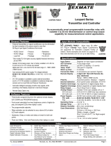
Measuring AC Volts and Frequency, this Dual-Display meter is housed
in a low-profile DIN 96 x24 mm short depth case
DD-40VHz
Dual AC Volt/Frequency
Dual 4 Digit with 0.3” LEDs
in a 1/16 DIN Case
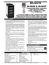
The DD-40VHz is a compact, dual 4.0 digit red LED display of
AC volts and frequency. The combination of ACV and Hz makes
the DD-40VHz ideal for generator set and other stand-by power
applications. Both the voltmeter and the frequency meter will
display to 0.1 resolution.
Each DD-40VHz has a two-position display intensity se lec tion.
With this display dimmer feature, the DD-40VHz can easily be
seen in direct sunlight. Then the low intensity setting can be
selected for night operation.
The DD-40VHz is housed in a short-depth 2.2" (111 mm) deep,
96X48 mm 1/16 DIN horizontal case. This compact case style
allows for maximum visibility while demanding a very small
panel space. The DD-40VHz uses a high-efficiency AC/DC
switching power supply that allows operation from any AC volt-
age (85 to 265 VAC) or DC voltage (90 to 380 VDC).
Input Configuration: ....... Single-ended input
A/D Convertor: .................14 Bit Single Slope
Accuracy: ........................± (0.2% of reading + 1 digit)
Temperature Coefficient: ..5 ppm/˚C in ratiometric mode
Warm up time: .................1 Minute
Conversion Rate: ............. 3 conversions per second
Display:.............................0.3" (7 mm) high red LEDs.
Dual 4.0 digit displays
Decimal Selection: .........Preselected to XXX.X for volts and
frequency
Over-range Indication: ....“----”
Power Supply: ................85 to 265 VAC / 90 to 380 VDC
switching power supply. 2 watts.
Operating Temperature: .. 0 °C to 60 °C
Storage Temperature: .....–20°C to +70°C
Relative Humidity: ...........95% (non-condensing)
Case Dimensions: ...........Bezel: 96X24 mm (3.62” X 0.95”)
Depth behind bezel: 56.5 mm (2.23”)
Plus 27 mm (1.06”) for Push-On connector
or plus 17.5 mm (0.68”) for Edge connector
Weight: .............................85 gms (3 oz)
170 gms (6 oz) when packed
The DD-Series have a matching DIN case style
that is complementary to the Lynx, Leopard
and Tiger family of meters. DD-Meters are
the OEM’s choice for economical switchboard
and process indication. For economy, each
model is dedicated to a specific application and
designed for quick and easy installation.
DD-Series
General Features Compatibility
Specifications
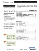
Typical Application Connections
DD-Series, the OEMs choice for switchboard and process indication
Span
DD-40VHZ
AC Power
Signal Input
Dim
1,A
3,C
6,F
8,J
14,R
15,S
DD-40VHZ .......................Dual Display of AC Volts (30.0 to 350.0V AC) and frequency (20.0 to 450.0 Hz)

Texmate, Inc. Tel. (760) 598-9899 • www.texmate.comPage 2 DD-40VHZ (DD1) Data Sheet
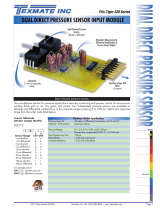
Functional Diagram
Connector Pinouts Component Layout
Pins 1 and A – Power Input: AC voltage from 85 to 265V
AC or 90 to 380V DC power may be applied. These pins are
internally connected.
Pins 2 and B – Not used: There is no in ter nal connection.
Pins 3 and C – Power Input: AC voltage from 85 to 265V
AC or 90 to 380 VDC power may be applied. These pins are
internally connected.
Pins 4 and D – Not used: There is no in ter nal connection.
Pins 5 and E – Not used: There is no in ter nal connection.
Pins 6 and F – Input Signal: These pins are internally con-
nect ed. Input voltage levels applied are from 30 VAC to 350
VAC. Maximum overload is 600 VAC / VDC.
Signal Conditioning Component
SPAN Potentiometer (Pot)
The 15 turn SPAN pot is always on the right side
(as viewed from the front of the meter). Typical
adjustment is 20% of the input signal range.
V
Hz
Micro-
processor
Rectified
and
averaged
AC-DC
Isolated
Power
Supply
Display
14
R
15
S
8
J
6
F
ACV
Signal
input
Displa
y
Dim
1
A
3
C
Power
Input
85 VA
C to
265 VAC
+5 VDC
Ground
1
A
2
B
3
C
45678910
DE FHJK
L
11 12 13 14 15
MN PRS
AC Power Signal Input Dim
The Texmate DD-40VHz uses a standard PC board edge con-
nector with two rows of 15 pins, spaced on 0.156" centers, for sig-
nal and power connection. The DD-40VHz is designed for simple
con nec tion to the signal source. There is only one signal input for
the AC voltage being monitored. The frequency is automatically
sensed and displayed on the right-hand side of the DD-40VHz.
The DD-40VHz is supplied from the factory with an in ter nal-
ly isolated auto-sensing AC/DC switching power supply. The
pow er supply will operate from an AC voltage within a range of
85 to 265 VAC and 90 to 380 VDC. If the power source to the
DD-40VHz changes from AC to DC, the DD-40VHz will continue
to operate. Although specified to operate from 85 to 265 VAC,
the DD-40VHz can still function with an AC supply as low as 40
VAC. Texmate recommends that the AC power source be within
the specified range of 85 to 265 VAC.
The AC input signal is rectified and averaged before being sam-
pled by a single-slope A/D converter. From the A/D con vert er,
the AC input signal and the digital rep re sen ta tion of the input
voltage are fed into a microprocessor to cal cu late the frequency.
Both the AC input voltage and the frequency are displayed on
two separate four-digit, seven- segment LED dis plays.
With an external switch, the meter display can be set to two
levels of brightness. The microprocessor de tects the dis play
selection setting of the switch and, in turn, applies this setting
to the display.
REAR OF METER WITH
PCB EDGE CONNECTOR MOUNT ED
Circuit Description
Pins 7 and H – Not used: There is no in ter nal connection.
Pins 8 and J – Input Signal: These pins are internally con-
nect ed. Input voltage levels applied are from 30 VAC to 350
VAC. Maximum overload is 600 VAC / VDC.
Pins 9 and K – Not used: There is no in ter nal connection.
Pins 10 and L – Not used: There is no in ter nal connection.
Pins 11 and M – Not used: There is no in ter nal connection.
Pins 12 and N – Not used: There is no in ter nal connection.
Pins 13 and P – Not used: There is no in ter nal connection.
Pins 14 and R – Display Dim Connection: Short to Pin 14 or
R to decrease the display intensity by 50%.
Pins 15 and S – Display Dim Connection: Short to Pin 12 or
N to decrease the display intensity by 50%.
Span Pot
METER REAR WITH PCB EDGE CONNECTOR MOUNTED
(For mounting of screw terminal blocks see rear page)
AC/DC Power Input - 1
AC/DC Power Input - 3
Not Used - 10
A - AC/DC Power Input
L - Not Used
J - Signal Low Input
Signal High Input - 6
Signal Low Input - 8
F - Signal High Input
COMPONENT SIDE PINS SOLDER SIDE PINS
Not Used - 12
Not Used - 13
Display Dim - 14
Not Used - 11 M - Not Used
N - Not Used
P - Not Used
R - Display Dim
C - AC/DC Power Input
Display Dim Common - 15 S - Display Dim Common
AC AC
AC AC
SIG
SIG
SIG
SIG
SW SW

Texmate, Inc. Tel. (760) 598-9899 • www.texmate.comDD-40VHZ (DD1) Data Sheet Page 3
Calibration Procedure
The DD-40VHz is calibrated at the factory with a precision AC
voltage source. A calibrator of 0.05% accuracy is re quired
to completely check the operation of the DD-40VHz meter.
The DD-40VHz is supplied from the factory with
an internally isolated auto-sensing AC/DC switching
power supply. This power supply will operate from an
AC voltage anywhere within a range of 85 to 265 VAC
or 90 to 370 VDC.
If the meter's power source changes from AC to
DC, the DD-40VHz will continue to operate. The
DD-40VHz, although specified to operate from 85 to
265 VAC, can still function with an AC supply as low as
40 VAC. It is recommended that the AC power source
be within the specified range of 85 to 265 VAC.
Span Pot
Front View
Filter
Clear Protective Cover
Bezel
A standard 30-pin edge card connector can be used to con-
nect the DD-40VHz. As an alternative, however Tex mate has
de signed an ex treme ly easy-to-use connector called the Push-
On™ connector. This exclusive connec tor de sign combines an
edge card con nec tor and screw terminal blocks into one piece.
To order, use part num ber DD-PUS H /DD.
Push-On Screw Terminals
Texmate’s exclusive optional Push-On Connectors combine an edge
card connector and a 10 position screw terminal block. Push-On
Connectors are ordered preconfigured for each specific power supply
voltage and each optional power supply available for the DD-Series.
Optional PCB Edge Card Connector
A standard 30 pin edge connector (two rows of 15 pins on
0.156" centers) may also be used to connect the DD-40VHZ.
Order part no. CN-L15.
They provide the greatest convenience and ease of use
Connector can be
securely attached
to case with screws
Pinouts are marked
on Connector
Custom Face Plates
Power Supply
Texmate Produces Thousands of
Custom OEM Face Plates
Have Texmate Design and produce a
Custom Face Plate for your next project!
• Custom face plates have a non-
recurring artwork charge. A serial
number is then assigned to each
artwork to facilitate reordering.
• Small Run or One-Off custom face plates incur an installation
charge, and are generally printed on a special plastic film, which is
then laminated to custom faceplate blanks as required.
• Large Run (300 pieces min): custom face plates are production
silk screened, issued a part number, and held in stock for free
installation as required by customer orders.
• OEMs may also order Custom Meter Labels, Box Labels, Custom
Data Sheets and Instruction Manuals.
1. Carefully snap off and remove the front bezel, clear pro-
tec-tive cover, and filter. The span adjust pot will now be
visible.
2. Make sure there is a proper AC or DC power source avail-
able that is within the specified pa ram e ters.
3. Connect the power source to Pins 1 and 3 (Pins A and C).
4. Connect the cal i bra tor to the input signal pins 6 and 8 (Pins
F and J) and apply an AC voltage between 90 and 350 VAC.
5. Adjust the span potentiometer at the front of the meter until
the displayed AC voltage reading agrees with the calibrator
input signal. Frequency calibration is not required.
6. The DD-40VHz is now calibrated and ready for use.

Texmate, Inc. Tel. (760) 598-9899 • www.texmate.comPage 4 DD-40VHZ (DD1) Data Sheet
Ordering Information
Case Dimensions and Panel Cutouts
Standard Options for this Model Number
Part Number Description List
BASIC MODEL NUMBER Includes plug in type screw terminals, stan-
dard display and standard power supply unless optional versions are
ordered.
DD-40VHz .......
4.0 digit, dual V/Hz display, 30-350 VAC/20-450 Hz input
$160
Special Options and Accessories
Part Number Description List
ACCESSORIES
DN.CAS96X24 . 96x24mm Complete Short Depth Case w/Bezel .$25
75-DBBZ96X24. Black Bezel for 96x24mm Case ...............$5
75-DMTC96X24
Mounting Slide Clips, extra set (96x24mm case size) .
$8
CN-L15 ....... Dual Row 15 Pin Edge Connector .............$8
CN-PUSH/DD .. Push-on Screw Terminal Block Connector......$45
OP-MTLCLIP ....
Screw Mounting Clips (2pc) to screw tighten slide brackets
$10
75-DTP96X24 ...Black Metal Trim Plate (96x24mm Case) 1 Meter ..$10
75-DTP2X9624 ..Black Metal Trim Plate (96x24mm Case) 2 Meters $10
75-DTP3X9624 ..Black Metal Trim Plate (96x24mm Case) 3 Meters $10
Prices subject to change without notice.
96 mm
(3.78")
1/16 DIN (96x24mm)
24 mm
(0.95")
3 mm
(0.12")
typical
FRONT VIEW
PANEL CUTOUT
22.2 mm
(0.88")
92 mm
(3.62")
21.85 mm
(0.86")
91 mm
(3.59")
Case will mount in
standard 1/16 DIN cutouts
TOP VIEW
97.8mm
(3.86")
91mm
(3.59")
Max. panel thickness
96mm
(3.78")
25.4mm
(3.78")
When extra panel mounting
tightness is required, optional
Screw Mounting Clips are included
which fit on the Mounting Slide Clips.
For additional strength, extra Mounting Slide Clips
can be ordered and doubled
up one behind the other.
P/N:(75-DMT96X24)
Various bezel colors are
available. Black is standard.
17.5mm
(0.69")
Edge Connector
P/N:(CN-L15)
SIDE VIEW
5mm
(0.20")
5.4mm
(0.21")
21.85 mm
(0.86")
27mm
(1.06")
Push-On Connector
P/N:(CN/PUSH/BN)
56.5mm
(2.23")
12345678910
BLANKHOLD
TEXMATE PUSH-ON CONNECTOR
+VE
DC
PWR
INPUT
HIGH
- VE
DC
PWR
INPUT
LO
1•
DP1
1X•
DP2
1XX•
DP3 COM
92.8 mm (3.6")
Widest mountable
panel cutout
without using
adaptors.
Top
Catches
TO REMOVE REAR COVER
Release Bottom Catch
with a small flat blade,
and lever outwards.
Bottom Catch
The 96x24mm case is particularly
suitable for mounting in mosaic panels
or insulative panels.
They can also stack
mount, 2 up in existing cut-outs for 1/8
DIN (96x48mm) or 4 up in 1/4 DIN
(96x96mm).
P
SP3
SP2
SP1
Loose Fit
Snug Fit
Panel adaptor plates are available to
retrofit most existing panel cutouts.
WARRANTY
Texmate warrants that its proDXcts are free from defects in material and workmanship under
normal use and service for a period of one year from date of shipment. Texmate’s obligations
under this warranty are limited to replacement or repair, at its option, at its factory, of any of
the proDXcts which shall, within the applicable period after shipment, be returned to Texmate’s
facility, transportation charges pre-paid, and which are, after examination, disclosed to the sat-
isfaction of Texmate to be thus defective. The warranty shall not apply to any equipment which
shall have been repaired or altered, except by Texmate, or which shall have been subjected
to misuse, negligence, or accident. In no case shall Texmate’s liability exceed the original pur-
chase price. The aforementioned provisions do not extend the original warranty period of any
proDXct which has been either repaired or replaced by Texmate.
USER’S RESPONSIBILITY
We are pleased to offer suggestions on the use of our various proDXcts either by way of printed
matter or through direct contact with our sales/application engineering staff. However, since
we have no control over the use of our proDXcts once they are shipped, NO WARRANTY
WHETHER OF MERCHANTABILITY, FITNESS FOR PURPOSE, OR OTHERWISE is made
beyond the repair, replacement, or refund of purchase price at the sole discretion of Texmate.
Users shall determine the suitability of the proDXct for the intended application before using,
and the users assume all risk and liability whatsoever in connection therewith, regardless
of any of our suggestions or statements as to application or construction. In no event shall
Texmate’s liability, in law or otherwise, be in excess of the purchase price of the proDXct.
Texmate cannot assume responsibility for any circuitry described. No circuit patent or software
licenses are implied. Texmate reserves the right to change circuitry, operating software, speci-
fications, and prices without notice at any time.
For product details visit www.texmate.com
Local Distributor Address
450 State Place • Escondido, CA 92029
Tel: 1-760-598-9899 • USA 1-800-839-6283 • That’s 1-800-TEXMATE
Fax: 1-760-598-9828 • Email: [email protected] • Web: www.texmate.com
Copyright © 2018 Texmate Inc. All Right Reserved.
/