Ruckus Wireless S9GR310 User manual
- Category
- WLAN access points
- Type
- User manual
This manual is also suitable for

Copyright © 2015 Ruckus Wireless, Inc. Page 1 of 4
Published 24 July 2015, Part Number 800-70972-001 Rev A
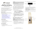
ZoneFlex R310 Access Point
Quick Setup Guide
This Quick Setup Guide provides step-by-step instructions on how to set up
your Ruckus Wireless ZoneFlex R310 access point. After completing the
steps in this guide, you will be able to place the access point at your site
and provide network access to wireless clients. The rest of this document
refers to the ZoneFlex R310 access point as an AP.
BEFORE YOU BEGIN
Before deploying your Ruckus Wireless device, please check the Ruckus
Wireless Web site for the latest software and release documentation.
• Release Notes and User Documents are available at
http://support.ruckuswireless.com/documents
• Software Upgrades are available at
http://support.ruckuswireless.com/software
• Open Source information is available at
http://support.ruckuswireless.com/open_source
THIS GUIDE IN OTHER LANGUAGES
• 请从以下网站获得该指南的简体中文版
https://support.ruckuswireless.com
• Vous trouverez la version française de ce guide à l'adresse suivante
https://support.ruckuswireless.com
• こ の ガ イ ド の日本語版は https://support.ruckuswireless.com
でご覧く ださい
• 이 가이드의 한국어 버전은 웹 사이트
(https://support.ruckuswireless.com
) 에서 확인하시기 바랍니
다
• Veja a versão em português (Brasil) deste guia em
https://support.ruckuswireless.com
• Puede ver la versión en español (América Latina) de esta guía en
https://support.ruckuswireless.com
Figure 1. ZoneFlex R310 AP
PACKAGE CONTENTS
• One ZoneFlex R310 access point
• Two mounting screws and plastic wall anchors
• One T8 5mm M2.5 Torx locking security screw
• One unit removal pin
• Regulatory flyer
• Product warranty statement
• Declaration of conformity, if required
• Ruckus Wireless AP Getting Started Guide
•This Quick Setup Guide
CONFIGURING THE AP
• Step 1: Collecting the AP MAC Address
• Step 2: Collecting Setup Requirements, Hardware, and Tools
• Step 3: Connecting Your Computer to the AP
• Step 4: Preparing Your Computer for AP Setup
• Step 5: Logging Into the AP Web Interface
• Step 6: Customizing the Wireless Settings
• Step 7: Placing the AP at the Site
• Step 8: Verifying the Installation
Step 1: Collecting the AP MAC Address
• Write down the MAC address (12 alphanumeric digits) from the
outside of the AP.
Step 2: Collecting Setup Requirements, Hardware,
and Tools
• A computer with Ethernet adapter running Windows 7 or equivalent,
with Firefox or equivalent web browser.
• One Cat 5e (or better) Ethernet cable.
• T8 Torx screwdriver.
• An AC-to-12VDC power adapter (sold separately)
--OR--
an 802.3af-compliant Power over Ethernet (PoE) switch or PoE
injector.
Step 3: Connecting Your Computer to the AP
A After removing the AP from its package, place it next to your
computer.
B Using an Ethernet cable, connect your computer’s network port to the
POE IN port on the AP.
C Connect the AC power adapter (sold separately) to the 12VDC AP
port, and plug the AC power adapter into a convenient and protected
AC power source.
Alternatively, connect the POE IN port to a PoE injector or PoE switch
for both power and network connectivity.
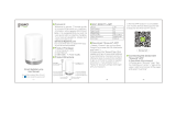
Figure 2. AP rear panel
D After bootup, verify that the PWR LED on the AP is a steady green.
Step 4: Preparing Your Computer for AP Setup
A On your Windows 7 computer, configure your network adapter from
the Local Area Connection settings as follows:
• Start > Control Panel > Network and Sharing
Center > Change Adapter Settings
Note:
The minimum software revision for the AP is base image 100.x or
later, SmartZone 3.2 or later, or ZoneFlex 10.0 or later.
The rest of this document collectively refers to the SCG SZ, vSZ, ZD,
and other controllers as Ruckus Wireless controllers.
Important!
If the AP is to be managed by a Ruckus Wireless controller, then
follow the controller user documents to connect the AP to your local
network and configure it for initial operation. In that case, you may not
need to complete the following steps.
Note:
The following procedures assume that Windows 7 is the operating
system. Procedures for other operating systems are similar.

Copyright © 2015 Ruckus Wireless, Inc. Page 2 of 4
Published 24 July 2015, Part Number 800-70972-001 Rev A
B Edit the TCP/IPv4 address settings as follows:
• Local Area Connection > Properties > Internet
Protocol Version 4 (TCP/IPv4) > Properties
The Internet Protocol Version 4 (TCP/IPv4) Properties dialog box
appears.
C Select Use the following IP address (if it is not already selected) and
then make the following entries:
• IP address: 192.168.0.22 (or any available address in the
192.168.0.x network, except 192.168.0.1, which is the default
used by the ZoneFlex R310 AP)
• Subnet mask: 255.255.255.0
• Leave the DNS server and Default gateway fields empty.
D Click OK to save your changes. Your changes are put into effect
immediately.
Step 5: Logging Into the AP Web Interface
As specified in Step 4: Preparing Your Computer for AP Setup, the
computer should be connected to your AP through the Ethernet port and
powered on, ready for setup.
A On your computer, open a Web browser window.
B In the browser, enter https://192.168.0.1 to connect to the AP.
C Press <Enter> to initiate the connection. When a security alert dialog
box appears, click OK/Yes to proceed.
D When the Ruckus Wireless Admin login page appears, enter the
following:
• Username: super
• Password: sp-admin
E Click Login.
Step 6: Customizing the Wireless Settings
A On the AP Web interface menu, click Configuration >
Wireless > 5G or Configuration > Wireless > 2.4G. The
Configure > Wireless > Common options appear.
B Verify that the following options are active:
• Channel: SmartSelect
• Channel Width: 20 MHz, 40 MHz, or 80 MHz (default).
• Country Code: Select the country in which the AP will be
operating.
C Click Update Settings if you made any changes.
D Click any of the eight Wireless # (Wireless LAN Number) tabs at the
top of the page.
E In Wireless Availability, click Enabled.
F Delete the text in the SSID field, and then type a name for your network
that will help your users identify the AP in their wireless network
connection application.
G Click Update Settings to save your changes.
H If required, repeat Steps D-G for any other Wireless # (Wireless LAN
Number) interface that you want to enable.
I Click Logout to exit the Web interface.
J Disconnect the AP from the computer and from the current power
source, and then restore your computer to its original network
configuration.
Step 7: Placing the AP at the Site
A Move the AP to its permanent location (accessible to both AC or PoE
power and network connection).
B Use a Cat 5e (or better) Ethernet cable to connect your network (or PoE
injector or switch) to the POE IN port on the AP.
--OR--
If you are not using an 802.3af-compliant PoE switch or PoE injector,
then connect the AC power adapter to the AP, and then to a
convenient power source.
C Verify that the POE IN port LED is lit.
Step 8: Verifying the Installation
A Using any wireless-enabled computer or mobile device, search for and
select the wireless network you previously configured.
B If you can connect, open a browser and link to any public Web site.
Congratulations! Your wireless network is active and ready for use. If you
need to configure advanced wireless settings, such as enabling security,
refer to the Ruckus Wireless Indoor AP User Guide.
INSTALLING THE AP
The AP can be mounted on a flat surface, on a drop-ceiling T-bar, or on a
pole or flat surface. Refer to the following sections:
• Mounting on a Flat Surface
• Removing the AP from Flat-Surface Mounting Screws
• Mounting the AP on a Drop-Ceiling T-Bar
• Removing the AP from a Drop-Ceiling T-Bar
• Mounting the AP on a Flat Surface or Pole Using the Optional
Secure Mounting Bracket
• Removing the AP from the Optional Secure Mounting Bracket
Mounting on a Flat Surface
The factory-supplied mounting screws and plastic wall anchors allow you
to attach the AP to a wall or ceiling.
A Use the Mounting Template on the last page of this guide to mark the
locations for two drill holes on the mounting surface.
B Use a 4.75mm (3/16”) drill bit to drill holes approximately 25mm (1”)
deep into the mounting surface.
C Insert the factory-supplied anchors (A in Figure 3
) and mounting
screws (B) into the mounting surface, leaving approximately 6 mm
(1/4”) of the screw heads protruding from the surface.
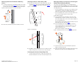
Figure 3. Mounting the AP on a flat surface
D Place the AP onto the mounting screws so that the screw heads enter
the keyholes on the AP enclosure (C), and gently press down on the AP
until the locking tab in the upper AP keyhole locks the AP onto the top
mounting screw.
Important!
Write down all of the currently active settings so you can restore your
computer to its current configuration when this procedure is
completed.
Note:
If you purchased the AP in the United States, then this value is fixed to
United States at the factory and is not user configurable. If you
purchased the AP outside the United States, then verify that the value
is set to your country or region. Selecting the correct country code
ensures that the AP uses only the radio channels allowed in your
country or region.
A
B
C

Copyright © 2015 Ruckus Wireless, Inc. Page 3 of 4
Published 24 July 2015, Part Number 800-70972-001 Rev A
Removing the AP from Flat-Surface Mounting
Screws
A To remove the AP from the factory-supplied mounting screws, gently
press the unit removal pin (A in Figure 4) into the access hole on the
end of the AP to release the bracket locking tab in the upper keyhole.
Figure 4. Removing the AP from the screw heads
B Push the AP up and pull it away from the mounting screw heads.
Mounting the AP on a Drop-Ceiling T-Bar
A Orient the AP so that the T-bar is positioned between the T-bar clips
as shown in Figure 5, then rotate the AP until the third T-bar clip
catches the T-bar and the latch locks the T-bar in place (Figure 6).
Figure 5. Initial position
Figure 6. Final position
B (OPTIONAL, for added security.) Using a Torx T8 screwdriver, insert the
locking screw (A) into the hole near the latch to lock the AP in place.
Removing the AP from a Drop-Ceiling T-Bar
• To remove the AP, first remove the security screw, then depress the
latch while rotating the AP so that the T-bar clips disengage the T-bar.
Mounting the AP on a Flat Surface or Pole Using the
Optional Secure Mounting Bracket
The customer-ordered Ruckus Wireless secure mounting bracket kit
(ordering part number 902-0120-0000) includes a metal mounting bracket
and provides greater security when attaching the AP to flat surfaces (walls
and ceilings) and to poles.
• If you are mounting the AP on a flat surface, then you will also need an
electric drill with a 4.75mm (3/16”) drill bit, and the four No. 6 zinc
plated screws and plastic wall anchors included with the kit.
• If you are mounting the AP on a truss or pole, then you will also need
the two customer-supplied stainless steel pipe clamps.
Continue with the following:
A If you are mounting the AP on a flat surface, then use the secure
mounting bracket as a template to mark the locations for four drill
holes on the mounting surface. There are four screw holes available on
the secure mounting bracket.
Fasten the bracket to the flat surface using four mounting screws and
plastic wall anchors and continue with Step C
.
B If you are mounting the AP on a pipe or pole, then feed the two
customer-supplied stainless steel clamps through the slots on the
secure mounting bracket. Use common hand tools to tighten the
clamps around the pipe or pole.
After the bracket is attached, continue with Step C
.
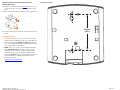
Figure 7. Attaching the AP to the secure mounting bracket
C Insert the two studs on the secure mounting bracket (A) into the
keyholes on the bottom of the AP.
D Slide the AP toward the Ethernet port until the locking tab in the upper
AP keyhole locks the AP onto the top mounting bracket stud.
A
A
A

Copyright © 2015 Ruckus Wireless, Inc. Page 4 of 4
Published 24 July 2015, Part Number 800-70972-001 Rev A
Removing the AP from the Optional Secure
Mounting Bracket
A Gently press the unit removal pin (A in Figure 8) into the access hole
on the end of the AP to release the bracket locking tab in the upper
keyhole.
Figure 8. Removing the AP from the secure mounting bracket
B Slide the AP toward the unit removal pin and remove the AP from the
bracket.
TROUBLESHOOTING
• CAUTION: If required, you can reset the AP to its factory default
settings by using a straightened paper clip to press and hold the reset
button located between the POE IN and 12VDC ports, for six or
more seconds. DO NOT DO THIS UNLESS SO INSTRUCTED. (Doing this
resets the AP IP address to 192.168.0.1.)
• NOTE: After a reset, you can access the internal AP web interface
using https://192.168.0.1. Your device must use any other
unused address from 192.168.0.2 through 192.168.0.254, with
subnet mask 255.255.255.0. The username is super, and the
password is sp-admin. Refer to the Ruckus Wireless Indoor AP User
Guide for information on configuring and operating the AP. This
document is available at
https://support.ruckuswireless.com
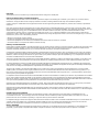
Mounting Template:
A
82.6mm
3.25in

Page 1
Important
The equipment is to be connected only to PoE networks without routing to the outside plant.
Federal Communications Commission Notices
This product complies with Part 15 of the FCC Rules. Operation is subject to the following two conditions: (1) this device may not cause harmful
interference, and (2) this device must accept any interference received, including interference that may cause undesired operation.
Caution: Changes or modifications to this equipment that have not been approved by Ruckus Wireless may void the user's authority to operate this
equipment.
Note: This equipment has been tested and found to comply with the limits for a Class B digital device, pursuant to part 15 of the FCC Rules. These
limits are designed to provide reasonable protection against harmful interference in a residential installation. This equipment generates, uses and can
radiate radio frequency energy and, if not installed and used in accordance with the instructions, may cause harmful interference to radio
communications. However, there is no guarantee that interference will not occur in a particular installation. If this equipment does cause harmful
interference to radio or television reception, which can be determined by turning the equipment off and on, the user is encouraged to try to correct the
interference by one or more of the following measures:
—Reorient or relocate the receiving antenna.
—Increase the separation between the equipment and receiver.
—Connect the equipment into an outlet on a circuit different from that to which the receiver is connected.
—Consult the dealer or an experienced radio/TV technician for help.
Industry Canada Statement
Under Industry Canada regulations, this radio transmitter may only operate using an antenna of a type and maximum (or lesser) gain approved for the
transmitter by Industry Canada. To reduce potential radio interference to other users, the antenna type and its gain should be so chosen that the
equivalent isotropically radiated power (e.i.r.p.) is not more than that necessary for successful communication.
Conformément à la réglementation d'Industrie Canada, le présent émetteur radio peut fonctionner avec une antenne d'un type et d'un gain maximal
(ou inférieur) approuvé pour l'émetteur par Industrie Canada. Dans le but de réduire les risques de brouillage radioélectrique à l'intention des autres
utilisateurs, il faut choisir le type d'antenne et son gain de sorte que la puissance isotrope rayonnée équivalente (p.i.r.e.) ne dépasse pas l'intensité
nécessaire à l'établissement d'une communication satisfaisante.
This device complies with Industry Canada licence-exempt RSS standard(s). Operation is subject to the following two conditions: (1) this device may
not cause interference, and (2) this device must accept any interference, including interference that may cause undesired operation of the device.
Le présent appareil est conforme aux CNR d'Industrie Canada applicables aux appareils radio exempts de licence. L'exploitation est autorisée aux
deux conditions suivantes : (1) l'appareil ne doit pas produire de brouillage, et (2) l'utilisateur de l'appareil doit accepter tout brouillage radioélectrique
subi, même si le brouillage est susceptible d'en compromettre le fonctionnement.
The device for operation in the band 5150-5250 MHz is only for indoor use to reduce the potential for harmful interference to co-channel mobile
satellite systems; the maximum antenna gain permitted for devices in the bands 5250-5350 MHz and 5470-5725 MHz shall comply with the e.i.r.p.
limit; and the maximum antenna gain permitted for devices in the band 5725-5825 MHz shall comply with the e.i.r.p. limits specified for point-to-point
and non point-to-point operation as appropriate.
Le dispositif de fonctionnement dans la bande 5150-5250 MHz est réservé à une utilisation en intérieur pour réduire le risque d'interférences nuisibles
à la co-canal systèmes mobiles par satellite, le gain d'antenne maximal autorisé pour les appareils dans les bandes 5250-5350 MHz et 5470-5725
MHz doit se conformer à la pire limite, et le gain d'antenne maximal autorisé pour les appareils dans la bande 5725-5825 MHz doivent être conformes
avec le pire limites spécifiées à point-à-ponctuelles et non point-à-point de fonctionnement selon qu'il convient.
Operation in the 5600-5650 MHz band is not allowed in Canada. High-power radars are allocated as primary users (i.e. priority users) of the bands
5250-5350 MHz and 5650-5850 MHz and that these radars could cause interference and/or damage to LE-LAN devices.
Opération dans la bande 5600-5650 MHz n'est pas autorisée au Canada. Haute puissance radars sont désignés comme utilisateurs principaux (c.-à-
utilisateurs prioritaires) des bandes 5250-5350 MHz et 5650-5850 MHz et que ces radars pourraient causer des interférences et / ou des dommages à
dispositifs LAN-EL.
Radiation Exposure Statement
The device has been found to be compliant to the requirements set forth in CFR 47 Sections 2.1091 and Industry Canada RSS-102 for an
uncontrolled environment. The antenna(s) used for this transmitter must be installed to provide a separation distance of at least 20 cm from all
persons and must not be co-located or operating in conjunction with any other antenna or transmitter.
Le dispositif a été jugé conforme aux exigences énoncées dans les articles 47 CFR 2.1091 et Industrie Canada RSS-102 pour un environnement non
contrôlé. L'antenne (s) utilisée pour ce transmetteur doit être installé pour fournir une distance de séparation d'au moins 20 cm de toutes les
personnes et ne doit pas être co-localisés ou fonctionner en conjonction avec une autre antenne ou transmetteur.
Mexico Statement
“La operación de este equipo está sujeta a las siguientes dos condiciones: (1) es posible que este equipo o dispositivo no cause interferencia
perjudicial y (2) este equipo o dispositivo debe aceptar cualquier interferencia, incluyendo la que pueda causar su operación no deseada.”

Page 2
Professionally Installed Products
The product is to be installed according to the installation instructions. The Use/Operator does not have access to the device once the device is
installed and in use. Provisions for permanent grounding are provided.
1. Installation personal: This product is designed for specific application and needs to be installed by a qualified personal who has RF and related rule
knowledge. The general user shall not attempt to install or change the setting.
2. Installation location: The product shall be installed at a location where the radiating antenna can be kept 20 cm from nearby person in normal
operation condition to meet regulatory RF exposure requirement. Additionally, installation locations with 35km of Terminal Doppler Weather Radar
locations shall follow instructions below.
a. Any installation of either a master or a client device within 35 km of a TDWR location shall be separated by at least 30 MHz center-to-
center) from the TDWR operating frequency.
b. A voluntary WISPA sponsored database has been developed that allows operators and installers to register the location information of the
UNII devices operating outdoors in the 5470 – 5725 MHz band within 35 km of any TDWR location (see
http://www.spectrumbridge.com/udia/home.aspx
). This database may be used by government agencies in order to expedite resolution of
any interference to TDWRs.
c. Addition information can be obtained from the FCC Knowledge Database, Publication Number 443999.
https://apps.fcc.gov/oetcf/kdb/index.cfm
3. External antenna: Use only the antennas which have been approved by Ruckus Wireless. The non-approved antenna(s) may produce unwanted
spurious or excessive RF transmitting power which may lead to the violation of FCC limit and is prohibited.
4. Installation procedure: Please refer to user’s manual for the detail.
5. Warning: Please carefully select the installation position and make sure that the final output power does not exceed the limit set force in US Rule
CFR 47 part 15 section 15.247 & 15.407. The violation of the rule could lead to serious federal penalty.
External Antenna Notice
This radio transmitter has been approved by the FCC and Industry Canada to operate with the antenna types listed below with the maximum
permissible gain and required antenna impedance for each antenna type indicated. Antenna types not included in this list, having a gain greater than
the maximum gain indicated for that type, are strictly prohibited for use with this device.
Le présent émetteur radio (identifier le dispositif par son numéro de certification ou son numéro de modèle s'il fait partie du matériel de catégorie I) a
été approuvé par Industrie Canada pour fonctionner avec les types d'antenne énumérés ci-dessous et ayant un gain admissible maximal et
l'impédance requise pour chaque type d'antenne. Les types d'antenne non inclus dans cette liste, ou dont le gain est supérieur au gain maximal
indiqué, sont strictement interdits pour l'exploitation de l'émetteur.
Model: ZoneFlex 7441 [ZF7441]: This device has been designed to operate with an antenna having maximum gain of 2dBi. Other antenna types or
having greater gain are strictly prohibited for use with this device. The required antenna impedance is 50 ohms.
Model: ZoneFlex 7372E [ZF7372E]: This device has been designed to operate with an antenna having maximum gain of 7dBi. Other antenna types
or having greater gain are strictly prohibited for use with this device. The required antenna impedance is 50 ohms.
Products intended to be powered by an external power supply:
Caution –This product is intended to be supplied by a Listed Direct Plug-In Power Unit marked Class 2 or LPS (sub-clause 2.5 of standard EN 60950-
1). Available Ruckus power supplies intended for product operation are identified in the product datasheet. The last two digits of the power supply
part number represent the country code. For additional applicable power supplies/options, see user instructions and product datasheet.
Medical Statement
Ruckus Wireless Access Points shall only be used in ME systems where the intended EM ENVIRONMENT does NOT rely on the WLAN radio link for
BASIC SAFETY or ESSENTIAL PERFORMANCE of the ME SYSTEM.
Australia Statement
This device complies with the ACMA requirements for a Wi-Fi device namely Radio Communications (Low Impact Potential Devices) Class Licence
2000 Amd. 1:2007 and Radiocommunications (Compliance Labelling – Electromagnetic Radiation) Notice 2003. The equipment complies with the
ACMA requirements for radiation exposure for a "general user/non-aware user". This equipment should be installed and operated with a minimum
distance of 20 cm between the radiator and your body. This equipment complies with the Australian safety requirements and should only used with
the specified power adapter according to the product datasheet.
Brazil Statement
For Brazil, those products are designed for specific application and needs to be installed by a qualified personal who has RF and related rule
knowledge. Regarding the operation on range of 5150 MHz to 5350 MHz , the average output power of the equipments must be adjusted to the
maximum limit of - 0,48 dBm and for 5470 MHz to 5725 MHz, the average output power of the equipments must be adjusted to the maximum limit of
6,44 dBm.
Para o Brasil, esses produtos são projetados para aplicações específicas e necessidades a serem instalados por um pessoal qualificado que tenha
conhecimento regra RF e afins.Em relação à operação em série de 5150 MHz a 5350 MHz, a potência média de saída dos equipamentos deve ser
ajustado para o limite máximo de - 0,48 dBm e para 5470 MHz a 5725 MHz, a potência média de saída dos equipamentos deve ser ajustada ao limite
máximo de 6,44 dBm.
Taiwan Statement
本產品為 5.25-5.35 GHz 頻帶內操作之 UNII 設備, 僅限於室內使用 The frequency band 5250 – 5350 MHz is restricted to indoor use.
經型式認證合格之低功率射頻電機,非經許可,公司、商號或使用者均不得擅自變更頻率、加大功率或變更原設計之特性及功能。
低功率射頻電機之使用不得影響飛航安全及干擾合法通信;經發現有干擾現象時,應立即停用,並改善至無干擾時方得繼續使用。前項合法通信,指依
電信法規定作業之無線電通信。低功率射頻電機須忍受合法通信或工業、科學及醫療用電波輻射性電機設備之干擾.

Page 3
The control, adjustment and on/off operation of this device does not violate the “Administrative regulations on low power radio waves radiated
devices”. Any adjustments to the device should be carried out or be monitored by a specialist who has expertise on radio frequency devices.
Replacement of components which may lead to the violation to the regulations is not allowed. Without permission granted by the NCC, any company,
enterprise, or user is not allowed to change frequency, enhance transmitting power or alter original characteristic as well as performance to an
approved low power radio-frequency devices. The low power radio-frequency device shall not influence aircraft security and interfere with legal
communications; if found, the user shall cease operating immediately until no interference is achieved. The said legal communications means radio
communications is operated in compliance with the Telecommunications Act. The low power radio-frequency devices must not be susceptible with the
interference from legal communications or ISM radio wave radiated devices.
European Union Notices and National Restrictions
The frequency band 5150 – 5350 MHz is restricted to indoor use
Italy
This product meets the National Radio Interface and the requirements specified in the National Frequency
Allocation Table for Italy. Unless operating within the boundaries of the owner’s property, the use of this 2.4 GHz Wireless LAN product requires a
‘general authorization’. Please check with http://www.comunicazioni.it/ for more details.
Questo prodotto è conforme alla specifiche di Interfaccia Radio Nazionali e rispetta il Piano Nazionale di ripartizione delle frequenze in Italia. Se non
viene installato all’interno del proprio fondo, l’utilizzo di prodotti Wireless LAN a 2.4 GHz richiede una "Autorizzazione Generale". Consultare
http://www.comunicazioni.it/ per maggiori dettagli.
Belgium
The Belgian Institute for Postal Services and Telecommunications (BIPT) must be notified of any outdoor wireless link having a range exceeding 300
meters. Please check http://www.bipt.be for more details. / Draadloze verbindingen voor buitengebruik en met een reikwijdte van meer dan 300 meter
dienen aangemeld te worden bij het Belgisch Instituut voor postdiensten en telecommunicatie (BIPT). Zie http://www.bipt.be voor meer gegevens. /
Les liaisons sans fil pour une utilisation en extérieur d’une distance supérieure à 300 mètres doivent être notifiées à l’Institut Belge des services
Postaux et des Télécommunications (IBPT). Visitez http://www.ibpt.be pour de plus amples détails.
Česky
[Czech]
Ruckus Wireless tímto prohlašuje, že tento Radio LAN je ve shodě se základními požadavky a dalšími příslušnými
ustanoveními směrnice 1999/5/ES.
Dansk
[Danish]
Undertegnede Ruckus Wireless erklærer herved, at følgende udstyr Radio LAN overholder de væsentlige krav og øvrige
relevante krav i direktiv 1999/5/EF.
Deutsch
[German]
Hiermit erklärt Ruckus Wireless, dass sich das Gerät Radio LAN in Übereinstimmung mit den grundlegenden
Anforderungen und den übrigen einschlägigen Bestimmungen der Richtlinie 1999/5/EG befindet.
Eesti
[Estonian]
Käesolevaga kinnitab Ruckus Wireless seadme Radio LAN vastavust direktiivi 1999/5/EÜ põhinõuetele ja nimetatud
direktiivist tulenevatele teistele asjakohastele sätetele.
English Hereby, Ruckus Wireless declares that this Radio LAN is in compliance with the essential requirements and other
relevant provisions of Directive 1999/5/EC.
Español
[Spanish]
Por medio de la presente Ruckus Wireless declara que el Radio LAN cumple con los requisitos esenciales y cualesquiera
otras disposiciones aplicables o exigibles de la Directiva 1999/5/CE.
Ελληνική
[Greek]
ΜΕ ΤΗΝ ΠΑΡΟΥΣΑ Ruckus Wireless ∆ΗΛΩΝΕΙ ΟΤΙ Radio LAN ΣΥΜΜΟΡΦΩΝΕΤΑΙ ΠΡΟΣ ΤΙΣ ΟΥΣΙΩ∆ΕΙΣ
ΑΠΑΙΤΗΣΕΙΣ ΚΑΙ ΤΙΣ ΛΟΙΠΕΣ ΣΧΕΤΙΚΕΣ ∆ΙΑΤΑΞΕΙΣ ΤΗΣ Ο∆ΗΓΙΑΣ 1999/5/ΕΚ.
Français
[French]
Par la présente Ruckus Wireless déclare que l'appareil Radio LAN est conforme aux exigences essentielles et aux autres
dispositions pertinentes de la directive 1999/5/CE.
Italiano
[Italian]
Con la presente Ruckus Wireless dichiara che questo Radio LAN è conforme ai requisiti essenziali ed alle altre
disposizioni pertinenti stabilite dalla direttiva 1999/5/CE.
Latviski
[Latvian]
Ar šo Ruckus Wireless deklarē, ka Radio LAN atbilst Direktīvas 1999/5/EK būtiskajām prasībām un citiem ar to
saistītajiem noteikumiem.
Lietuvių
[Lithuanian]
Šiuo Ruckus Wireless deklaruoja, kad šis Radio LAN atitinka esminius reikalavimus ir kitas 1999/5/EB Direktyvos
nuostatas.
Nederlands
[Dutch]
Hierbij verklaart Ruckus Wireless dat het toestel Radio LAN in overeenstemming is met de essentiële eisen en de andere
relevante bepalingen van richtlijn 1999/5/EG.
Malti
[Maltese]
Hawnhekk, Ruckus Wireless, jiddikjara li dan Radio LAN jikkonforma mal-ħtiġijiet essenzjali u ma provvedimenti oħrajn
relevanti li hemm fid-Dirrettiva 1999/5/EC.
Magyar
[Hungarian]
Alulírott, Ruckus Wireless nyilatkozom, hogy a Radio LAN megfelel a vonatkozó alapvetõ követelményeknek és az
1999/5/EC irányelv egyéb elõírásainak.
Polski
[Polish]
Niniejszym Ruckus Wireless oświadcza, że Radio LAN jest zgodny z zasadniczymi wymogami oraz pozostałymi
stosownymi postanowieniami Dyrektywy 1999/5/EC.
Português
[Portuguese]
Ruckus Wireless declara que este Radio LAN está conforme com os requisitos essenciais e outras disposições da
Directiva 1999/5/CE.
AT FI IT PL GB RO
BE FR LV PT IS TR
CY DE LT SK LI
CZ GR LU SI NO
DK HU MT ES CH
EE IE NL SE BG

Page 4
Slovensko
[Slovenian]
Ruckus Wireless izjavlja, da je ta Radio LAN v skladu z bistvenimi zahtevami in ostalimi relevantnimi določili direktive
1999/5/ES.
Slovensky
[Slovak]
Ruckus Wireless týmto vyhlasuje, že Radio LAN spĺňa základné požiadavky a všetky príslušné ustanovenia Smernice
1999/5/ES.
Suomi
[Finnish]
Ruckus Wireless vakuuttaa täten että Radio LAN tyyppinen laite on direktiivin 1999/5/EY oleellisten vaatimusten ja sitä
koskevien direktiivin muiden ehtojen mukainen.
Svenska
[Swedish]
Härmed intygar Ruckus Wireless att denna Radio LAN står I överensstämmelse med de väsentliga egenskapskrav och
övriga relevanta bestämmelser som framgår av direktiv 1999/5/EG.
Íslenska
[Icelandic]
Hér með lýsir Ruckus Wireless yfir því að Radio LAN er í samræmi við grunnkröfur og aðrar kröfur, sem gerðar eru í
tilskipun 1999/5/EC.
Norsk
[Norwegian]
Ruckus Wireless erklærer herved at utstyret Radio LAN er i samsvar med de grunnleggende krav og øvrige relevante
krav i direktiv 1999/5/EF.
800-70402-002-J
-
 1
1
-
 2
2
-
 3
3
-
 4
4
-
 5
5
-
 6
6
-
 7
7
-
 8
8


Ruckus Wireless S9GR310 User manual
- Category
- WLAN access points
- Type
- User manual
- This manual is also suitable for
Ask a question and I''ll find the answer in the document
Finding information in a document is now easier with AI
Related papers
-
Ruckus Wireless ZoneFlex 7363 User manual
-
Ruckus Wireless ZoneFlex 7352 Quick Setup Manual
-
Ruckus Wireless ZoneFlex R500 Quick Setup Manual
-
Ruckus Wireless ZoneFlex R710 Quick Setup Manual
-
 Ruckus Wireless MediaFlex 7211 Installation guide
-
Ruckus Wireless ZoneFlex 7982 Quick Setup Manual
-
 Ruckus Wireless ZoneFlex 7731 User manual
-
 Ruckus Wireless T300 Mounting Manual
-
Ruckus Wireless ZoneFlex 7372-E Quick Setup Manual
-
Ruckus Wireless ZoneFlex P300 Quick Setup Manual


Other documents
-
Ausounds Intelligence T20B User manual
-
 Gosund LB3 User manual
-
Shenzhen SL3 Smart LED Light strip User manual
-
SunPower PVS6 Installation guide
-
-
Lorex B451AJ-Z User manual
-
Suzhou 360 Robotic Technology 360 S8 Series Robot Vacuum Cleaner User manual
-
SENAO OAP8250AG User manual
-
Motorola Verizon VAP2500 Quick start guide
-
Amigo API51X Installation guide
