Frigidaire FFHT1835VSxx Installation guide

Type
Installation guide
INSTALLATION INSTRUCTIONS
FRONT CONTROL FREESTANDING ELECTRIC RANGE
IMPORTANT SAFETY INSTRUCTIONS
If the information in this manual is not followed
exactly, a re or electrical shock may result causing property
damage, personal injury or death.
Important Notes to the Installer:
Read all instructions contained in these installation
instructions before installing range.
Remove all packing material from the oven
compartments before connecting the gas & electrical
supply to the range.
Observe all governing codes and ordinances.
Be sure to leave these instructions with the consumer.
Important Notes to the Consumer:
Keep these instructions with your owner’s guide for future
reference.
As when using any appliance generating heat, there
are certain safety precautions you should follow. These
are listed in the Use & Care Guide, read it carefully.
Be sure your range is installed and grounded properly
by a qualied installer or service technician.
Make sure the wall coverings around the range can
withstand the heat generated by the range.
To eliminate the need to reach over the surface
elements, cabinet storage space above the elements
should be avoided.
Tip Over Hazard
Range
leveling leg Anti-tip
bracket
• A child or adult can tip the
range and be killed.
• Verify the anti-tip device has
been installed to floor or wall.
• Ensure the anti-tip device is re-engaged to floor
or wall when the range is moved.
• Do not operate the range without the anti-tip
device in place and engaged.
• Failure to follow these instructions can result in
death or serious burns to children and adults.
To check if the anti-tip bracket is installed properly, use
both arms to grasp the rear edge of the range back.
Carefully attempt to tilt range forward. When properly
installed, the range should not tilt forward.
Refer to the anti-tip bracket installation instructions
supplied with your range for proper installation.
809127106 REV A (06/2022)
English - 1-8
Español - 9-16
Français - 17-24
INSTALLATION AND SERVICE MUST BE
PERFORMED BY A QUALIFIED INSTALLER.
IMPORTANT: SAVE FOR LOCAL ELECTRICAL INSPECTOR'S USE.
READ AND SAVE THESE INSTRUCTIONS FOR FUTURE REFERENCE.
FOR YOUR SAFETY: Do not
store or use gasoline or other ammable
vapors and liquids in the vicinity of this or
any other appliance.
United States Canada
Printed in USA
Impreso en EE. UU.
Imprimé aux États-Unis
2
30” ELECTRIC FRONT CONTROL FREESTANDING INSTALLATION INSTRUCTIONS
1. Clearances and Dimensions
a. Provide adequate clearances between the range and adjacent combustible surfaces.
b. Location—Check location where the range will be installed. Check for proper electrical supply and the stability of oor.
c. Dimensions that are shown must be used. Given dimensions provide minimum clearance. Contact surface must be
solid and level.
*30" (762 mm) MINIMUM CLEARANCE BETWEEN THE
TOP OF THE COOKING SURFACE AND THE BOTTOM
OF AN UNPROTECTED WOOD OR METAL CABINET;
OR 24" (610 mm) MINIMUM WHEN BOTTOM OF WOOD
OR METAL CABINET IS PROTECTED BY NOT LESS
THAN 1/4" (6 mm) FLAME RETARDANT MILLBOARD
COVERED WITH NOT LESS THAN NO. 28 MSG SHEET
STEEL, 0.015" (0.4 mm) STAINLESS STEEL, 0.024"
(0.6 mm) ALUMINUM OR 0.020" (0.5 mm) COPPER.
0" (0 mm) CLEARANCE IS THE MINIMUM FOR THE
REAR OF THE RANGE. FOLLOW ALL DIMENSION
REQUIREMENTS PROVIDED ABOVE TO PREVENT
PROPERTY DAMAGE, POTENTIAL FIRE HAZARD, AND
INCORRECT COUNTERTOP AND CABINET CUTS.
TO ELIMINATE THE RISK OF BURNS OR FIRE BY
REACHING OVER HEATED SURFACE UNITS, CABINET
STORAGE SPACE LOCATED ABOVE THE SURFACE
UNITS SHOULD BE AVOIDED. IF CABINET STORAGE
IS TO BE PROVIDED, THE RISK CAN BE REDUCED
BY INSTALLING A RANGE HOOD THAT PROJECTS
HORIZONTALLY A MINIMUM OF 5" (127 mm) BEYOND
THE BOTTOM OF THE CABINETS.
Fig. 2
Fig. 1
Fig. 3
1” 30” Minimum*
Minimum to
wall on either
side of range
above 36” height.
36”
18”
Minimum to
cabinets on
either side
of range
25” Max.
13”
Maximum depth
for cabinets
above range top.
0” clearance below cooking top and at rear of ran
ge
Typical cabinet installationFront
view
Side
view
30”
Minimum
30” Minimum
Dashed cubed area
shows where the electrical outlet should be
installed for flush to the wall installation.
Wall
Edge
26"
Door Open -
47 5/16
35 ± 3/8” Min
36 ± 3/8” Max
30"
Fig. 1
3
30” ELECTRIC FRONT CONTROL FREESTANDING INSTALLATION INSTRUCTIONS
2. Tools You Will Need
3. Anti-Tip Bracket Installation
Instructions
To reduce the risk of tipping of the range,
the range should be secured to the oor by properly
installed anti-tip bracket and screws packed with the
range. Failure to install the anti-tip bracket will allow the
range to tip over if excessive weight is placed on an open
door or if a child climbs upon it. Serious injury might result
from spilled hot liquids or from the range itself.
If range is ever moved to a dierent location, the anti-tip
brackets must also be moved and installed with the range.
Instructions are provided for installation in wood or cement
fastened to either the oor or wall. When installed to the
wall, make sure that screws completely penetrate dry wall
and are secured in wood or metal. When fastening to the
oor or wall, be sure that screws do not penetrate electrical
wiring or plumbing.
A. Locate the Bracket Using the Template - (Bracket may
be located on either the left or right side of the range.
Use the information below to locate the bracket if
template is not available). Mark the oor or wall where
left or right side of the range will be located. If rear of
range is against the wall or no further than 1-13/16"
(46 mm) from wall when installed, you may use the
wall or oor mount method. If molding is installed and
does not allow the bracket to t ush against the wall,
remove molding or mount bracket to the oor. For wall
mount, locate the bracket by placing the back edge of
the template against the rear wall and the side edge
of template on the mark made referencing the side of
the range. Place bracket on top of template and mark
location of the screw holes in wall.
For leveling legs and Anti-Tip Bracket:
Adjustable wrench or channel lock
pliers
5/16" Nutdriver or Flat Head
Screwdriver
Electric Drill & 1/8" Diameter
Drill Bit (Masonry Drill Bit if
installing in concrete)
Level & Measuring Tape
For electrical supply connection:
1/4" & 3/8" Socket driver or Nutdriver
Additional Materials You Will Need:
Power Supply Cord or
Copper Electrical Wiring & Metal
Conduit (for hard wiring)
If rear of range is further than 1-13/16” (46 mm) from
the wall when installed, attach bracket to the oor. For
oor mount, locate the bracket by placing back edge
of the template where the rear of the range will be
located. Mark the location of the screw holes, shown
in template.
B. Drill Pilot Holes and Fasten Bracket - Drill a 1/8”
(3 mm) pilot hole where screws are to be located. If
bracket is to be mounted to the wall, drill pilot hole at
an approximate 20° downward angle. If bracket is to
be mounted to masonry or ceramic oors, drill a 5/32”
(4 mm) pilot hole 1-3/4” (44 mm) deep. The screws
provided may be used in wood or concrete material.
Use a 5/16” (8 mm) nut-driver or at head screwdriver
to secure the bracket in place.
Fig. 4
Fig. 5
Fig. 6
(45.6 mm)
1-13/16” Max.
(45.6 mm)
More than
1-13/16”
4
30” ELECTRIC FRONT CONTROL FREESTANDING INSTALLATION INSTRUCTIONS
C. Level and Position Range - Level range by adjusting
the (4) leveling legs with a wrench. Note: Aminimum
clearance of 1/8” (3 mm) is required between the
bottom of the range and the leveling leg to allow
room for the bracket. Use a spirit level to check your
adjustments. Slide range back into position. Visually
check that rear leveling leg is inserted into and fully
secured by the Anti-Tip Bracket by removing lower
panel or storage drawer.
4. Electrical Connection
Requirements
Avoid re hazard or electrical shock.
Failure to follow this warning may casue serious injury,
re, or death.
This appliance must be properly installed and grounded
by a qualied technician in accordance with the National
Electrical Code ANSI/NFPA No. 70 or Canadian Electrical
Code (CSA Standard (C22.1 Part 1) latest editions, and
Local Electrical Code requirements.
For personal safety, this appliance must be properly
grounded. For maximum safety, the power cord must be
plugged into an electrical outlet that is correct voltage, is
correctly polarized and properly grounded in accordance
with local codes.
It is the personal responsibilty of the consumer to have the
appropiate outlet with the correct, properly grounded wall
receptacle installed by a qualied electrician.
Fig. 7
5. Models Including Power
Cord (Canada)
Plug the 4-prong range power cable into a properly
grounded, 240V wall outlet.
240V grounded
wall receptacle
Power supply
cord with 4-prong
grounding plug
Range Side or
Cabinet Side
(0”, 0.5 mm)
Fig. 8
5
30” ELECTRIC FRONT CONTROL FREESTANDING INSTALLATION INSTRUCTIONS
Fig. 13
6. Installing Power Cords
(United States)
RISK OF FIRE OR ELECTRICAL SHOCK MAY OCCUR IF
AN INCORRECT SIZE RANGE CORD KIT IS USED, THE
INSTALLATION INSTRUCTIONS ARE NOT FOLLOWED
OR STRAIN RELIEF BRACKET IS DISCARDED.
This appliance may be connected by means of a power
supply cord. Use a power supply cord kit rated at 125/250
volts minimum, marked for use with ranges.
Cord must have either three (3) or four (4) conductors.
Terminals on end of wires must be either closed loop or
open-end spade lugs with upturned ends.
Cord must have strain relief properly installed.
Access the Terminal Block
1. Remove the access cover and bracket from the back
of the appliance. Keep all pieces and the screws.
2. Pull the cord terminals through the correct hole in the
bracket included with the appliance.
3. Connect the terminals to the terminal block
as instructed for 3-wire, 4-wire, or permanent
connections. See the next section for specic
instructions for each connection.
4. Place the strain relief through the included bracket and
tighten against the power cord.
5. Replace the bracket and access cover on the
appliance.
Required for new and
remodeled installations
4-Wire Wall
receptacle (14-50R)
Allowed for
existing installations
3 Wire Wall
receptacle (10-50R)
Fig. 10
Fig. 11
Fig. 9
Fig. 12
6
30” ELECTRIC FRONT CONTROL FREESTANDING INSTALLATION INSTRUCTIONS
3-Wire Power Cord Connection
(Existing installations ONLY)
A ground strap is installed on this range which connects
the center terminal of the terminal block (Neutral) to the
range chassis. The ground strap is connected to the range
by the center screw (see Fig. 15). The ground strap must
not be removed unless National, State or Local Codes do
not permit use of a ground strap.
NOTE: If the ground strap is removed for any reason, a
separate ground wire must be connected to the separate
ground screw attached to the range chassis and to an
adequate ground source.
1. Insert the end connectors for Line 1, Line 2 and
Neutral and tighten securely to the terminal block.
IMPORTANT NOTE: DO NOT LOOSEN the factory
installed nut connections which secure the range
wiring to the terminal block. Electrical failure or loss
of electrical connection may occur if these 3 nuts are
loosened or removed.
2. Follow the manufacturer’s installation instructions
supplied with the strain relief and install.
3. Make sure all connections are tightened securely and
replace the rear access cover.
Fig. 15Fig. 14
NOTE: Internal white wire not present on all models.
4-Wire Power Cord Connection
(New branch-circuit or mobile home)
1. Insert the end connectors for Line 1, Line 2 and
Neutral and tighten securely to the terminal block.
IMPORTANT NOTE: DO NOT LOOSEN the factory
installed nut connections which secure the range
wiring to the terminal block. Electrical failure or loss
of electrical connection may occur if these nuts are
loosened or removed.
2. You must disconnect the ground strap. Remove the
factory installed ground screw and plate to release the
copper ground strap from the frame of the appliance.
Cut and discard the copper ground strap and plate.
Keep the ground screw.
3. Connect the GREEN ground wire lead with the eyelet
to the frame of the appliance with the ground screw
using the same hole in the frame where the ground
screw was originally installed.
4. Follow the manufacturer’s installation instructions
supplied with the strain relief and install.
5. Make sure all screws are tightened securely and
replace the rear access cover.
4
BLACK
L1
RED
WHITE
NEUTRAL
GREEN
L2
Remove ground strap 3
BLACK
L1
RED
WHITE
NEUTRAL
L2
Ground screw
and plate
Ground
strap
NOTE: Internal white wire not present on all models.
7
30” ELECTRIC FRONT CONTROL FREESTANDING INSTALLATION INSTRUCTIONS
3-Wire and 4-Wire Permanent
Connection
This appliance may be connected by means of permanent
wiring.
When installing permanent wiring, do not leave excess
wire in range compartment. Excess wire in the range
compartment may not allow the rear access cover to be
replaced properly and could create a potential electrical
hazard if wires become pinched. Connect only as
instructed. When using exible conduit or range cable use
ex connector or range cable strain relief.
1. Strip insulation away from the ends of the permanent
wiring for Line 1, Line 2, Neutral (also strip ground wire
on 4-Wire Connections). Tighten all wire leads to the
terminal block (Follow wire locations shown in Fig. 16).
IMPORTANT NOTE: DO NOT LOOSEN the factory
installed nut connections which secure the range
wiring to the terminal block. Electrical failure or loss
of electrical connection may occur if these nuts are
loosened or removed.
2. (4-Wire Permanent Connection ONLY) Disconnect
the ground strap. Remove the factory installed ground
screw and plate to release the factory installed copper
ground strap from frame of the appliance. Cut and
discard the copper strap from the terminal block. Keep
the ground screw and ground plate.
3. (4-Wire Permanent Connection ONLY) Connect the
ground wire lead (Green) to the frame of the appliance
using the ground screw & plate as shown in Fig. 17.
Be sure to install using the same hole in the frame
where the ground screw was originally installed.
4. Follow the manufacturer’s installation instructions
supplied with the strain relief and install.
5. Make sure all connections are tightened securely and
replace the rear access cover.
NOTE: Non-terminated eld wire compression
connections must be set at 22 in./lbs. or greater. Always
use 10 gauge wire or larger.
Fig. 16
Fig. 17
L1
NEUTRAL
L2
Ground screw
and ground plate
Ground
strap
Tighten
all leads
8
30” ELECTRIC FRONT CONTROL FREESTANDING INSTALLATION INSTRUCTIONS
Care, Cleaning and
Maintenance
Refer to the Use & Care Manual for cleaning instructions.
If removing the range is necessary for cleaning or
maintenance, disconnect the electrical power supply. If
the electrical supply is inaccessible, lift the unit slightly at
the front and pull out away from the wall. Pull only as far
as necessary to disconnect the electrical supply. Finish
removing the unit for servicing and cleaning.
Before You Call for Service
Read the "Before You Call" and operating instruction
sections in your Use & Care Manual. It may save you time
and expense. The list includes common occurrences that
are not the result of defective workmanship or materials in
this appliance.
Refer to the warranty in your Use & Care Manual for our
toll-free service number and address. Please call or write
if you have inquiries about your range product and/or need
to order parts.
Model and Serial Number
Location
The serial plate is located on the front of the appliance, visible
when the door is opened.
When ordering parts for or making inquires about your
range, always be sure to include the model and serial
numbers and a lot number or letter from the serial plate on
your range.
Your serial plate also tells you the Kilowatt rating (power
requirements) and Voltage ratings.
Fig. 18
7. Carefully Slide Range Into
Final Location
Be sure to provide all the adequate clearances and
dimensions before moving appliance into nal location.
Carefully slide range into nal position while inserting rear
leveling leg into the anti-tip bracket. Make sure the power
cord folds into the remaining open oor area behind the
range. Be sure to check the level of the range.
INSTRUCCIONES DE INSTALACION
LA ESTUFA ELECTRICA DE 30”
INSTRUCCIONES IMPORTANTES DE SEGURIDAD
Si no se sigue estrictamente la información
de este manual, se puede producir un incendio o un choque
eléctrico que cause daños materiales, lesiones corporales o
fatales.
Notas Importantes para el Instalador:
Lea todas las instrucciones indicadas en estas
instrucciones de instalación antes de instalar la estufa.
Saque todo el material de empaque del compartimiento
del horno antes de conectar el suministro de gas y de
electricidad a la estufa.
Observe todos los códigos y reglamentos vigentes.
Asegúrese de dejar estas instrucciones con el usuario.
Aviso importante al consumidor:
Mantenga estas instrucciones con su Guía de Uso y
Cuidado para referencia futura.
Al igual que con cualquier electrodoméstico que genere
calor, existen ciertas precauciones de seguridad que
usted debe seguir. Tales precauciones se encuentran en
la Guía de Uso y Cuidado, léala atentamente.
Asegúrese de que la estufa esté bien instalada y sea
puesta a tierra en forma debida por un instalador
calicado o un técnico de servicio.
Asegúrese de que el revestimiento de la pared alrededor
de la estufa pueda resistir el calor generado por la estufa.
Para eliminar la necesidad de tener que pasar sobre los
elementos, se recomienda no instalar armarios arriba los
elementos de la cubierta de la estufa.
809127106 REV A (06/2022)
English - 1-8
Español - 9-16
Français - 17-24
LA INSTALACION Y EL SERVICIO DEBEN SER
EFECTUADOS POR UN INSTALADOR CALIFICADO.
IMPORTANTE: CONSERVE ESTAS INSTRUCCIONES PARA
USO DEL INSPECTOR LOCAL DE ELECTRICIDAD.
LEA Y CONSERVE ESTAS INSTRUCCIONES PARA REFERENCIA FUTURA.
PARA SU SEGURIDAD: No
almacene ni use gasolina u otros vapores
y líquidos inamables cerca de este o
cualquier otro electrodoméstico.
Estados Unidos Canadá
Printed in USA
Impreso en EE. UU.
Imprimé aux États-Unis
Riesgo de volcamiento
• Un niño o adulto puede volcar la estufa y
acabar muerto.
• Verifique que se haya instalado el
dispositivo antivuelco en el piso o en la
pared.
Asegúrese de que el dispositivo antivuelco se haya reacoplado
cuando mueva la estufa sobre el piso o a la pared.
No utilice la estufa sin el dispositivo antivuelco instalado y
acoplado.
Si no se siguen estas instrucciones, se puede provocar la muerte
o quemaduras graves en niños y adultos.
Tornillo
nivelador de
la estufa Soporte
antivuelco
Para verificar si el soporte antivuelco está instalado
correctamente, sostenga el borde trasero de la parte
trasera de la estufa usando ambos brazos. Intente inclinar
la estufa hacia adelante con cuidado. Si está instalada
correctamente, la estufa no debería inclinarse hacia
adelante.
Consulte las instrucciones de instalación del soporte
antivuelco proporcionadas con la estufa para instalarlo
adecuadamente.
WARNING:
10
INSTRUCCIONES DE INSTALACION PARA LA ESTUFA ELECTRICA DE 30”
1. Espacios y dimensiones
a. Proporcione espacios adecuados entre la estufa y las supercies combustibles adyacentes.
b. Ubicación—Examine el lugar en el cual va a ser instalada la estufa. Determine la existencia de suministro eléctrico
adecuado y la estabilidad del piso.
c. Se deben usar las medidas indicadas. Las dimensiones indicadas proporcionan espacio mínimo. La supercie de contacto
debe ser sólida y estar a nivel
*ESPACIO LIBRE MINIMO DE 30” ENTRE LA CUBIERTA
DE COCINAR DE LA ESTUFA Y LA PARTE INFERIOR
DE UN ARMARIO DE METAL O DE MADERA NO
PROTEGIDO; O 24” MINIMO CUANDO LA PARTE
INFERIOR DE UN ARMARIO DE METAL O DE MADERA
ESTA PROTEGIDA CON CARTON RETARDANTE
A LAS LLAMAS DE NO MENOS DE 1/4 CUBIERTO
CON CHAPA DE ACERO NO INFERIOR AL NO. 28
MSG, ACERO INOXIDABLE DE 0.015”, ALUMINO DE
0.024” O COBRE DE 0.020”. EL ESPACIO LIBRE DE
0 ES EL MINIMO PARA LA PARTE TRASERA DE LA
ESTUFA. SIGA TODAS LAS DIMENSIONES INDICADAS
ANTERIORMENTE PARA EVITAR DAÑOS MATERIALES,
RIESGOS DE INCENDIO Y CORTES INCORRECTOS
DE LOS ARMARIOS Y DE LAS MESADAS.
PARA ELIMINAR EL RIESGO DE QUEMADURAS O
INCENDIOS AL PASAR SOBRE LOS ELEMENTOS
CALIENTES, SE DEBE EVITAR COLOCAR ARMARIOS
DE ALMACENAMIENTO SOBRE LA ESTUFA. SI
SE INSTALAN ARMARIOS SOBRE LA ESTUFA, SE
PUEDEN REDUCIR TALES RIESGOS INSTALANDO
UNA CAMPANA EXTRACTORA QUE SE PROYECTE
HORIZONTALMENTE UN MINIMO DE 5 MAS AFUERA
DE LA PARTE INFERIOR DE LOS ARMARIOS.
Fig. 2
Fig. 1
Fig. 3
Dashed cubed area
shows where the electrical outlet should be
installed for flush to the wall installation.
Wall
Edge
26"
Puerta abierta -
47 5/16
35 ± 3/8” Min
36 ± 3/8” Max
30"
Fig. 1
Vista
frontal
Vista
lateral
Instalación típica del gabinete
Mínimo a la pared
en cualquier lado
del rango por
encima de 36
pulgadas de altura
Mínimo para
gabinetes a cada
lado del rango Profundidad máxima
para gabinetes arriba
del rango superior
0 pulgadas de espacio libre debajo de la parte superi-
or de la cocina y en la parte trasera del estufa
El área discontinua discontinua muestra
dónde debe instalarse la toma de corri-
ente para instalarla a nivel de la pared.
Borde de
la pared
1"
36"
30" Min
18"
25" Max
13"
30" Min
30" Min
11
INSTRUCCIONES DE INSTALACION PARA LA ESTUFA ELECTRICA DE 30”
2. Herramientas que va a
necesitar
3. Instrucción para la instalación
de las jaciones de anti-inclinación
Para reducir el riesgo de inclinación de la
cocina, ésta debe ser asegurada hacia el piso con las jaciones
de anti-inclinación y los tornillos que vienen con la cocina. Si
no instala las jaciones, corre el riesgo que su cocina pueda
inclinarse si pone demasiado peso sobre la puerta abierta o si
un niño sube sobre ésta. Esto podría ocasionar graves lesiones
causadas por derrames de líquidos calientes o por la propria
cocina.
Si la cocina es trasladada a otro lugar, las jaciones de anti-
inclinación deben también ser trasladadas y instaladas con la
cocina.
Las instrucciones provistas sirven para instalación en suelo de
madera o concreto. Al jar los tornillos al suelo, asegurase que
no atraviesen la instalación eléctrica o de fontanería.
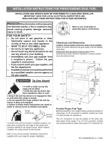
A. Ubicación del soporte utilizando la plantilla - (El
soporte puede ser ubicado ya sea en el lado izquierdo
o derecho de la estufa. Use la información indicada a
continuación para colocar el soporte si no se dispone de
la plantilla). Marque el piso o la pared donde se colocará
el costado izquierdo o derecho de la estufa. Si la parte
trasera de la estufa será colocada contra la pared o a no
más de 1-13/16" (46 mm) de la pared cuando ya esté
instalada, usted puede usar el método de instalación
en el piso o en la pared. Si tiene moldura instalada
y ésta no permite que el soporte quede a ras contra
la pared, retire la moldura o instale el soporte en el
piso. Para el montaje en la pared, ubique la plantilla
colocando el borde trasero de la plantilla contra la
pared trasera y el borde lateral de la plantilla en
la marca hecha indicando el costado de la estufa.
Coloque el soporte sobre la plantilla y marque la
ubicación de los agujeros de los tornillos en la pared.
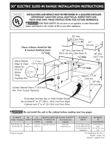
Si la parte trasera de la estufa está a más de 1-13/16”
(46 mm) de la pared cuando ya está instalada, instale el
soporte en el piso. Para el montaje en el piso, ubique el
soporte colocando el borde trasero de la plantilla donde
quedará ubicada la parte trasera de la estufa. Marque la
ubicación de los agujeros de los tornillos mostrados en la
plantilla.
B. Taladre agujeros pilotos e instale el soporte - Taladre
un agujero piloto de 1/8” donde se vayan a instalar los
tornillos. Si el soporte va a ser instalado en la pared,
taladre un agujero piloto en un ángulo descente de
aproximadamente 20°. Si el soporte va a ser instalado en
pisos de mampostería o de cerámica, taladre un agujero
piloto de 5/32” y 1-3/4” (44 mm) de profundidad. Los
tornillos provistos pueden ser usados en materiales de
madera o concreto. Use una llave de tuerca de 5/16” (8
mm) o un destornillador de punta plana para asegurar el
soporte en su lugar.
Fig. 4
Fig. 5
Fig. 6
Para patas de nivelación y montura anti-
vuelco
Llave ajustable o alicates
Llave para apretar tuercas de 5/16” o
un destornillador de cabeza plana
Taladro eléctrico y una broca de 1/8”
(broca de taladro de hormigón de
5/32” si se instala sobre hormigón)
Nivel & Cinta de medición
Para la conexión del suministro eléctrico:
Llave de boca tubular o llave para
tuercas de 1/4” y 3/8”
Materiales adicionales necesarios
Cordón eléctrico o Alambre eléctrico
de cobre y conducto metálico (para
alambrado permanente)
Soporte antivuelco
Montaje en la pared
Placa mural
Montaje en el piso
Parte trasera de la estufa
ASEGURE EL SOPORTE
(montaje en la pared o en el piso)
Pata Niveladora
(45.6 mm)
1-13/16” Max.
Pared
Pata Niveladora
Parte trasera de la estufa
ASEGURE EL SOPORTE
(montaje en el piso solomente)
Montaje en el piso Soporte antivuelco
(45.6 mm)
Más de 1-13/16”
12
INSTRUCCIONES DE INSTALACION PARA LA ESTUFA ELECTRICA DE 30”
C. Nivele y ubique la estufa - Nivele la estufa ajustando los
cuatro (4) tornillos niveladores con una llave. Nota: Se
debe dejar un espacio libre mínimo de 1/8” (3 mm) entre
la parte inferior de la estufa y los tornillos niveladores a
n de dejar espacio para instalar el soporte. Use un nivel
de burbuja de aire para vericar los ajustes. Deslice la
estufa de nuevo a su lugar. Verique visualmente si el
tornillo nivelador trasero está insertado y rmemente
asegurado por el soporte antivuelco retirando el panel
inferior o la gaveta de almacenamiento.
4. Requisitos de conexión
eléctrica
Evite peligro de incendio o descarga eléctrica.
El incumplimiento de esta advertencia puede causar lesiones
graves, incendios o la muerte.
Este aparato debe estar instalado en forma apropiada y
puesto a tierra por un técnico calicado, de acuerdo con el
National Electric Code (Código Nacional de Electricidad)
ANSI/NFPA No. 70 o el Canadian Electrical Code (Código
Eléctrico Canadiense) CSA Standrd C22.1 Part 1, última
ediciónes, y con los requerimientos de electricidad de los
códigos locales.
Para su seguridad personal, el electrodoméstico debe
estar debidamente conectado a tierra. Para una máxima
seguridad, el cable de alimentación debe estar enchufado
a una toma de corriente correctamente polarizada y
debidamente puesta a tierra de acuerdo con los códigos
locales.
El consumidor tiene la responsabilidad personal de
asegurarse de que un electricista calicado instala la toma
adecuada con un receptáculo de pared debidamente
puesto a tierra.
Fig. 7
5. Modelos con cable de
alimentación (Canadá)
Enchufe el cable de alimentación de la estufa de 4 clavijas
en un tomacorriente de pared de 240 V debidamente
conectado a tierra.
240V tomacorriente de
pared connectado a tierra
Bajar el cable de
smuinistro con
enchufe a tierra
de 4puntos
Fig. 8
Deslizar
la estufa
ha
cia atrás
Lado de la cocina o lado del gabinete
(0”, 0.5 mm)
13
INSTRUCCIONES DE INSTALACION PARA LA ESTUFA ELECTRICA DE 30”
Fig. 13
6. Instalación de cables de
alimentación (EE. UU.)
EL RIESGO DE INCENDIO O DESCARGAS ELÉCTRICAS
PUEDE OCURRIR SI SE UTILIZA UN KIT DE CABLE
DE ALCANCE INCORRECTO, NO SE SIGUEN LAS
INSTRUCCIONES DE INSTALACIÓN O SE DESCARTÓ EL
SOPORTE DE ALIVIO.
Este electrodoméstico se puede conectar por medio de un
cable de suministro de energía. Solo se usará un kit de cable
de suministro de potencia con una clasicación de 125/250
voltios como mínimo y marcado para su uso con rangos.
Acceder al bloque de terminales
1. Retire la cubierta de acceso y el soporte de la parte
posterior del aparato. Guarde todas las piezas y los
tornillos.
2. Tire de los terminales del cable a través del oricio
correcto en el soporte incluido con el aparato.
3. Conecte los terminales al bloque de terminales
como se indica para conexiones de 3 hilos, 4 hilos
o permanentes. Consulte la siguiente sección para
obtener instrucciones especícas para cada conexión.
4. Coloque el alivio de tensión a través del soporte
incluido y apriete contra el cable de alimentación.
5. Vuelva a colocar el soporte y la cubierta de acceso en
el aparato.
Fig. 11
Tabla del Tamaño de la Abertura de Conexión de la Estufa
Informació sobre la potencia nominal en amperios del Juego de Cable de
Alimentación. Ver la placa de serie en la estufa para los datos sobre la
potencia nominal en kilovatios.
Ver la placa de serie en la
estufa para la potencia
nominal en kilovatios
120/240 Voltios 120/208 Voltios
Diámetro (pulg.) de la
Abertura de Conexión de la
Estufa
Potencia
Nominal del
Juego de
cable Juego de
cable
Cableado
Permanente
1-3/8"
1-3/8"
1-1/8"
1-3/8"
40/50 Amp.
50 Amp.
8,8-16,5 KW 7,9-12,5 KW
16,6-22,5 KW 12,6-18,5 KW
Fig. 9
Fig. 12
Fig. 10
Requerido para nuevo y
instalaciones remodeladas
Pared de 4 hilos
receptáculo(14-50R)
Permitido por
instalaciones existentes
Pared de 3 hilos
receptáculo (10-50R)
El cable debe tener un alivio de tensión instalado
correctamente.
El cable debe tener tres (3) o cuatro (4) conductores.
Los terminales en el extremo de los cables deben ser
terminales de bucle cerrado o de extremo abierto con
extremos hacia arriba.
14
INSTRUCCIONES DE INSTALACION PARA LA ESTUFA ELECTRICA DE 30”
Conexión trilar
(SOLO instalaciones existentes)
Esta estufa tiene instalada una cinta de conexión a tierra
que conecta el borne central del tablero de bornes (neutro)
al chasis de la estufa. La cinta de conexión a tierra está
conectada a la estufa mediante el tornillo central más
inferior (ver Fig. 15). La cinta de conexión de tierra no
debe retirarse a menos que el código nacional, estatal o
local no permitan el uso de una cinta de conexión a tierra.
NOTA: Si por cualquier motivo se retira la cinta de
conexión a tierra, se debe conectar un alambre de tierra
separado al tornillo de tierra instalado en el chasis de la
estufa y a una tierra adecuada.
1. Inserte los conectores de extremo para la Línea 1,
Línea 2 y Neutro y apriete rmemente en el tablero
de bornes. NOTA IMPORTANTE: NO AFLOJE las
conexiones de tuerca instaladas en la fábrica que
aseguran el cableado de la estufa en el tablero
de bornes. Se puede producir una falla eléctrica o
pérdida de la conexión eléctrica si estas 3 tuercas son
aojadas o retiradas.
2. Siga las instrucciones de instalación del fabricante
suministradas con el sujetacable e instale.
3. Asegúrese de que todas las tuercas estén rmemente
apretadas y vuelva a colocar la cubierta de acceso
trasera.
Fig. 15
Fig. 14
NOTA: El cable blanco interno no está presente en todos
los modelos.
Conexión tetralar
(Nuevo circuito derivado o casa móvil)
1. Inserte los conectores de extremo para la Línea 1,
Línea 2 y Neutro y apriete rmemente en el tablero
de bornes. NOTA IMPORTANTE: NO AFLOJE las
conexiones de tuerca instaladas en la fábrica que
aseguran el cableado de la estufa en el tablero
de bornes. Se puede producir una falla eléctrica o
pérdida de la conexión eléctrica si estas 3 tuercas son
aojadas o retiradas.
2. Usted debe desconectar la cinta de conexión a
tierra. Retire el tornillo y placa de tierra instalada en
la fábrica para soltar la cinta de conexión a tierra de
cobre del marco del electrodoméstico. Conserve el
tornillo de tierra.
3. Conecte el alambre de VERDE puesta a tierra con el
ojal en el marco del electrodoméstico con el tornillo
de tierra usando el mismo agujero del marco donde
estaba originalmente instalado el tornillo de tierra.
4. Siga las instrucciones de instalación del fabricante
suministradas con el sujetacable e instale.
5. Asegúrese de que todas las tuercas estén rmemente
apretadas y vuelva a colocar la cubierta de acceso
trasera.
4
NEGRO
L1
ROJO
BLANCO
NEUTRAL
VERDE
L2
Retire la correa de tierra
3
L1
NEUTRAL
L2
Placa y tornillo
de tierra
Cinta de
tierra
NEGRO
ROJO
BLANCO
NOTA: El cable blanco interno no está presente en todos
los modelos.
15
INSTRUCCIONES DE INSTALACION PARA LA ESTUFA ELECTRICA DE 30”
Connexiones del cableado permanente
trilar y tetralar
Este aparato puede conectarse mediante cableado
permanente.
Cuando instale un cableado permanente, no deje el exceso
de cable en el compartimento de rango. El exceso de
cable en el compartimiento de rango puede no permitir
que la cubierta de acceso posterior sea reemplazada
adecuadamente y podría crear un riesgo eléctrico potencial si
los cables se pellizcan. Conéctelo únicamente como se indica
en “Conexiones de cableado permanente” en el Paso 4c. Al
usar un conducto exible o cable de rango, use un conector
exible o un alivio de tensión del cable de rango.
1. Desforre el aislamiento de los extremos del cableado
permanente para la Línea 1, Línea 2, Neutro (además
desforre el alambre de conexión a tierra en las
conexiones tetralares). Apriete los 3 conductores
hacia el tablero de bornes (Siga las ubicaciones de
los alambres que se muestran en la Fig. 16). NOTA
IMPORTANTE: NO AFLOJE las conexiones de tuerca
instaladas en la fábrica que aseguran el cableado de
la estufa en el tablero de bornes. Se puede producir
una falla eléctrica o pérdida de la conexión eléctrica si
estas 3 tuercas son aojadas o retiradas.
2. (Conexión permanente tetralar SOLAMENTE)
Desconecte la cinta de conexión a tierra. Retire el
tornillo y placa de tierra instalada en la fábrica para
soltar la cinta de conexión a tierra de cobre del marco
del electrodoméstico. Conserve el tornillo de tierra y la
placa de tierra.
3. (Conexión permanente tetralar SOLAMENTE)
Conecte el alambre terminal de puesta a tierra (verde)
al marco del electrodoméstico usando el tornillo y la
placa de conexión a tierra, como se muestra en la Fig.
17. Asegúrese de instalarlo usando el mismo agujero
del marco donde estaba originalmente instalado el
tornillo de tierra.
4. Siga las instrucciones de instalación del fabricante
suministradas con el sujetacable e instale.
5. Asegúrese de que todas las tuercas estén rmemente
apretadas y vuelva a colocar la cubierta de acceso
trasera.
NOTA: Los campos de la compresión de las conexiones de
los cables no terminadas deben ser usadas utilizando un
cable de 10 ga. o más grande y ajustarlos a aproximadamente
22 libras por pulgadas.
Fig. 16
Fig. 17
L1
NEUTRAL
L2
Apretar todos
los cables
Placa y tornillo
de tierra
Cinta de
tierra
16
INSTRUCCIONES DE INSTALACION PARA LA ESTUFA ELECTRICA DE 30”
Cuidado, limpieza y
mantenimiento
Consulte el Manual de uso y cuidado para las instrucciones
de limpieza.
Si es necesario retirar el rango para la limpieza o el
mantenimiento, desconecte el suministro de energía
eléctrica. Si el suministro eléctrico es inaccesible,
levante la unidad ligeramente hacia adelante y retírese
de la pared. Tire solo hasta donde sea necesario para
desconectar el suministro eléctrico. Termine de quitar la
unidad para dar servicio y limpiarla.
Antes de llamar al servicio
Lea las secciones “Antes de llamar” y la instrucción
de operación en su Manual de uso y cuidado. Puede
ahorrarle tiempo y dinero. La lista incluye las ocurrencias
comunes que no son el resultado de mano de obra o
materiales defectuosos en este electrodoméstico.
Consulte la garantía en su Manual de uso y cuidado para
obtener nuestro número y dirección de servicio gratuito.
Llame o escriba si tiene preguntas sobre su producto de
gama y / o si necesita pedir repuestos.
Ubicación del modelo y número
de serie
La placa de serie se encuentra en la parte frontal del aparato,
visible cuando se abre la puerta.
Cuando ordene piezas o pregunte acerca de su rango,
siempre asegúrese de incluir los números de modelo y de
serie y un número de lote o letra de la placa de serie en su
rango.
Su placa de serie también le indica la clasicación de
kilovatios (requisitos de potencia) y las clasicaciones de
voltaje.
Fig. 18
7. Deslice con cuidado la estufa
hasta su lugar denitivo
Asegúrese de proveer todos los espacios libres
adecuados y las dimensionesantes de mover la estufa a
su lugar denitivo.
Deslice cuidadosamente la estufa hacia la abertura del
gabinete a la vez que inserta el tornillo nivelador trasero
en el soporte antivuelco. Asegúrese de que el cordón de
alimentación quede plegado en el resto del área abierta
del piso detrás de la estufa. Asegúrese de vericar la
nivelación de la estufa.
INSTALLATION INSTRUCTIONS
CUISINIÈRE ÉLECTRIQUE
DIRECTIVES IMPORTANTES DE SÉCURITÉ
Si les directives contenues dans ce guide
ne sont pas suivies à la lettre, un feu ou une explosion
pourrait se produire et entraîner des dommages matériels,
des blessures, voire la mort.
Remarques importantes pour l’installateur
Lisez toutes les instructions contenues dans ce guide
avant de procéder à l’installation de la cuisinière.
Retirez tout le matériel d’emballage des compartiments
du four avant de connecter la cuisinière à l’alimentation
en gaz et à l’alimentation en électricité.
Respectez tous les codes et tous les règlements.
Assurez-vous de laisser ces instructions à l’utilisateur.
Remarque importante pour l’utilisateur :
Conservez ces instructions avec le guide d’utilisation et
d’entretien pour vous y reporter ultérieurement.
Comme pour tout appareil produisant de la chaleur,
certaines précautions de sécurité doivent être
respectées. Ceux-ci sont répertoriés dans le Guide
d’Utilisation et d’entretien, lisez-le attentivement.
Assurez-vous que votre cuisinière est installée et
mise à la terre de façon appropriée par un installateur
qualié ou un technicien de service.
Assurez-vous que les revêtements muraux autour de
la cuisinière peuvent supporter la chaleur générée par
la cuisinière.
Pour éliminer le besoin d’atteindre les éléments de
surface, l’espace de rangement des armoires au-
dessus des éléments devrait être évité.
809127106 REV A (06/2022)
English - 1-8
Español - 9-16
Français - 17-24
L’INSTALLATION ET L’ENTRETIEN DOIVENT ÊTRE EFFECTUÉS
PAR UNINSTALLATEUR QUALIFIÉ.
IMPORTANT: CONSERVEZ POUR L’INSPECTEUR D’ÉLECTRICITÉ LOCAL.
LISEZ ET CONSERVEZ CES INSTRUCTIONS POUR RÉFÉRENCES ULTÉRIEURES.
POUR VOTRE SÉCURITÉ:
N’entreposez pas ou n’utilisez pas
d’essence ou d’autres produits
inammables à proximité de cet appareil ou
de tout autre appareil électroménager.
États-Unis Canada
Printed in USA
Impreso en EE. UU.
Imprimé aux États-Unis
Risque de basculement
Un enfant ou un adulte peut faire
basculer la cuisinière et en décéder.
• Vérifiez que le dispositif anti-renverse-
ment a été fixé au plancher ou au mur.
• Assurez-vous d’enclencher le dispositif anti-renversement
lorsque la cuisinière est déplacée sur le plancher ou contre le
mur.
Ne faites pas fonctionner la cuisinière si le dispositif anti-ren-
versement n’est pas en place et enclenché.
Le non-respect de ces instructions peut causer des blessures
fatales ou de graves brûlures aux enfants et aux adultes.
Pied de mise à
niveau de la
cuisinière Support anti-
renversement
Pour vérifier si le support anti-renversement est correctement installé,
attrapez le bord arrière de la cuisinière à deux mains. et essayez
doucement de faire basculer la cuisinière vers l’avant. Lorsque le
support est correctement installé, la cuisinière ne doit pas basculer
vers l’avant.
Reportez-vous aux instructions d’installation du support anti-ren-
versement fournies avec la cuisinière pour vous assurer que
l’installation est effectuée de façon appropriée.
18
INSTRUCTIONS D’INSTALLATION DE LA COMMANDE ÉLECTRIQUE FRONTALE DE 30 PO
1. Dégagements et dimensions
a. Prévoyez des dégagements adéquats entre la cuisinière et les surfaces combustibles adjacentes.
b. Emplacement: vériez l’emplacement la plage sera installée. Vériez l’alimentation électrique et l’alimentation en gaz et la stabilité du sol.
c. Les dimensions achées doivent être utilisées. Les dimensions données fournissent un dégagement minimum. La surface de
contact doit être solideand level.
*ESPACE MINIMUM DE 76,2 CM (30) ENTRE LE DESSUS
DE LA SURFACE DE CUISSON ET LE DESSOUS D’UNE
ARMOIRE EN BOIS OU EN MÉTAL NON PROTÉGÉE,
OU ESPACE MINIMUM DE 61 CM (24) SI LE FOND DE
L’ARMOIRE EN BOIS OU EN MÉTAL EST PROTÉGÉ PAR
UN PANNEAU RÉSISTANT AU FEU D’AU MOINS 0,64
CM (1/4) RECOUVERT D’UNE FEUILLE D’ACIER DOUX
DONT L’ÉPAISSEUR EST AU MOINS DE 0,038 CM (0,015”)
SI EN ACIER INOXYDABLE; DE 0,061 CM (0,024”) SI EN
ALUMINIUM OU DE 0,051CM (0,020”) SI EN CUIVRE.
AUCUN ESPACE EST REQUIS À L’ARRIÈRE. RESPECTEZ
TOUTES LES DIMENSIONS INDIQUÉES CI DESSUS AFIN
D’ÉVITER DES DOMMAGES À LA PROPRIÉTÉ, DE CRÉER
UN DANGER POTENTIEL D’INCENDIE ET DE FAIRE DES
DÉCOUPAGES INCORRECTS DU COMPTOIR ET DE
L’ARMOIRE.
POUR ÉLIMINER LE RISQUE DE BRÛLURES OU D’INCENDIE
EN ATTEIGNANT LES UNITÉS DE SURFACE CHAUFFÉES,
L’ESPACE DE RANGEMENT DE L’ARMOIRE SITUÉ AU-
DESSUS DES UNITÉS DE SURFACE DOIT ÊTRE ÉVITÉ.
SI LE STOCKAGE DE L’ARMOIRE DOIT ÊTRE FOURNI, LE
RISQUE PEUT ÊTRE RÉDUIT EN INSTALLANT UNE HOTTE
DE CUISINIÈRE QUI SE PROJECTE HORIZONTALEMENT À
UN MINIMUM DE 5 “(127 mm) AU-DESSUS DU FOND DES
ARMOIRES.
Fig. 2
Fig. 3
Dashed cubed area
shows where the electrical outlet should be
installed for flush to the wall installation.
Wall
Edge
26"
porte ouverte -
47 5/16
35 ± 3/8” Min
36 ± 3/8” Max
30"
Fig. 1
La zone en cubes pointillés indique où
la prise électrique doit être installée
pour aeurer l’installation murale.
Bord de
mur
Vue de
face
Vue de
côté
Installation de cabinet typique
Minimum au mur
de chaque côté de
la plage au-dessus
de 36” de hauteur
Minimum aux
armoires de
chaque côté de
la cuisinière
Profondeur maximale
pour les armoires
au-dessus de la
cuisinière
0” Dégagement sous le dessus de cuisson et à
l’arrière de la cuisinière
1"
36"
30" Min
18"
25" Max
13"
30" Min
30" Min
19
INSTRUCTIONS D’INSTALLATION DE LA COMMANDE ÉLECTRIQUE FRONTALE DE 30 PO
2. Outils requis
3. Instructions d’installation du
support anti-basculement
La cuisinière doit être xée au plancher
pour éviter qu’elle ne se renverse. Ceci se réalise en
installant un support anti-bascule à l’aide des vis fournies
avec la cuisinière. Si le support n’est pas installé, la
cuisinière peut basculer lorsqu’un poids excessif est
exercé sur une porte ouverte ou qu’un enfant monte
dessus. Des blessures graves peuvent s’ensuivre
provenant de la cuisinière elle-même ou du renversement
de liquides chauds.
S’il faut déplacer la cuisinière à un autre endroit, le
support doit aussi être enlevé et réinstallé au nouvel
emplacement.
Les instructions fournies sont prévues pour l’installation
dans le bois ou dans le béton, dans le plancher. Lors
de l’installation, assurez-vous que les vis ne pénètrent
pas dans un câblage électrique ou des accessoires de
plomberie.
A. Situez le support en utilisant le gabarit- (Le support
peut être localisé à gauche ou à droite de la cuisinière.
Utilisez l’information donnée ci-après pour situer le
support si le gabarit n’est pas disponible.) Marquez
le plancher ou le mur à l’endroit où le côté gauche ou
droit de la cuisinière sera situé. Vous pouvez utiliser
la méthode de montage au mur ou au plancher si
l’arrière de la cuisinière est appuyé au mur ou pas
plus éloigné du mur que 46 mm (1-13/16”) après
installation. Enlevez la moulure ou xez le support
au plancher si une moulure est installée et ne permet
pas au support de s’appuyer fermement sur le mur.
Pour un montage contre le mur, situez le support en
plaçant la partie arrière du gabarit contre le mur arrière
et le bord du gabarit sur la marque faite qui identie le
côté de la cuisinière. Placez le support par-dessus le
gabarit et identiez l’emplacement des trous des vis
dans le mur.
Pour les pattes de nivellement et le
support anti-bascule:
Clé à molette ou princes multiprises
5/16” tournevis à douille ou
tournevis à tête plate
Perceuse & foret de 1/8 diamètre
(Si installer dans le béton,
foret de maçonnerie de 5/32”)
Niveau et ruban à mesurer
Pour le raccordement de
l’alimentation électrique:
1/4” & 3/8” Pilote de douille ou
Nutdriver
Matériel supplémentaire dont vous aurez
besoin:
Cordon d’alimentation ou
Câblage électrique et conduit en
métal (pour le câblage dur)
Fixez le support au plancher si l’arrière de la cuisinière
est plus éloigné que 46 mm (1-13/16”) du mur après
l’installation. Situez le support en plaçant la partie
arrière du gabarit à l’endroit où l’arrière de la cuisinière
sera localisé pour un montage sur le plancher.
Marquez l’emplacement des trous des vis indiqués sur
le gabarit.in template.
B. Percez les trous d’alignement et xez le support -
Percez un trou de 3 mm (1/8”) aux endroits où les
vis seront localisées. Percez un trou d’alignement à
un angle descendant d’approximativement 20º si le
support doit être installé sur le mur. Percez un trou
d’alignement de 4 mm (5/32”) par 44 mm (1-3/4”)
de profondeur si le support doit être installé dans la
maçonnerie ou des planchers de céramique. Les vis
fournies peuvent être utilisées dans le bois ou des
matériaux en béton. Utilisez un serre écrou ou un
tournevis plat an de xer le support en place.
Fig. 4
Fig. 5
Fig. 6
Support anti-renversement
Montage sur le mur
Lisse
Montage au plancher
Arrière de la cuisinre
FIXEZ LE SUPPORT
(montage au mur ou plancher)
Pied de Nivellement
(45.6 mm)
1-13/16” Max.
Mur
Pied de Nivellement
Arrière de la cuisinre
FIXEZ LE SUPPORT (montage au plancher seulement)
Montage au plancher Support anti-renversement
(45.6 mm)
Plus de 1-13/16
20
INSTRUCTIONS D’INSTALLATION DE LA COMMANDE ÉLECTRIQUE FRONTALE DE 30 PO
C. Mise en place et à niveau de la cuisinière - Mettez
la cuisinière à niveau en ajustant les (4) pattes de
mise à niveau à l’aide d’une clé à molette. Note : Un
espacement minimum de 3 mm (1/8”) requis entre
le bas de la cuisinière et la patte d’ajustement an
de permettre un espace pour le support. Utilisez un
niveau à bulle pour vérier vos ajustements. Glissez la
cuisinière vers sa position. Vériez visuellement que
la patte de mise à niveau arrière est complètement
insérée et xée dans le support de contre-
renversement en retirant le panneau inférieur ou le
tiroir de rangement.
4. Exigences de connexion
électrique
Évitez les risques d’incendie ou
d’électrocution. Le non-respect de cet avertissement peut
entraîner des blessures graves, un incendie ou la mort.
Cet appareil doit être correctement installé et mis à la terre
par un technicien qualié conformément aux dernières
éditions du Code national de l'électricité ANSI/NFPA n° 70
ou du Code canadien de l'électricité (norme CSA (C22.1
partie 1) et aux exigences du code électrique local.
Pour votre sécurité personnelle, cet appareil doit être
correctement mis à la terre. Pour une sécurité maximale,
le cordon d’alimentation doit être branché sur une prise
électrique de tension correcte, correctement polarisée et
correctement mise à la terre conformément aux codes
locaux.
Il est de la responsabilité personnelle du consommateur
d’avoir la prise appropriée avec la prise murale correcte
et correctement mise à la terre installée par un électricien
qualié.
Fig. 7 5. Modèles avec cordon
d’alimentation (Canada)
Branchez le câble d’alimentation à 4 broches de la
cuisinière dans une prise murale de 240 V correctement
mise à la terre.
Prise murale mise
à la terre de 240 V
Cordon d’alimentation
muni d’une fiche à
quatre broches avec
mise à la terre
Replacer
la cusinière
à sa place
Côté de la cuisinière ou côté côté de l'armoire
(0”, 0.5 mm)
Fig. 8
  • Page 1 1
  • Page 2 2
  • Page 3 3
  • Page 4 4
  • Page 5 5
  • Page 6 6
  • Page 7 7
  • Page 8 8
  • Page 9 9
  • Page 10 10
  • Page 11 11
  • Page 12 12
  • Page 13 13
  • Page 14 14
  • Page 15 15
  • Page 16 16
  • Page 17 17
  • Page 18 18
  • Page 19 19
  • Page 20 20
  • Page 21 21
  • Page 22 22
  • Page 23 23
  • Page 24 24

Frigidaire FFHT1835VSxx Installation guide

Type
Installation guide

Ask a question and I''ll find the answer in the document

Finding information in a document is now easier with AI