Page is loading ...

INSTALLATION AND SERVICE MUST BE PERFORMED BY A QUALIFIED INSTALLER.
IMPORTANT: SAVE FOR LOCAL ELECTRICAL INSPECTOR'S USE.
READ AND SAVE THESE INSTRUCTIONS FOR FUTURE REFERENCE.
Ifthe information in this manual is
not followed exactly, a fire or explosion may
result causing property damage, personal
injury or death.
FOR YOUR SAFETY:
m Do not store or use gasoline or other
flammable vapors and liquids in the
vicinity of this or any other appliance.
WHAT TO DO IF YOU SMELL GAS:
• Do not try to light any appliance.
• Do not touch any electrical switch; do not
use any phone in your building.
• Immediately call your gas supplier from
a neighbor's phone. Follow the gas
supplier's instructions.
• If you cannot reach yourgas supplier, call
the fire department.
Installation and service must be performed
by a qualified installer, service agency or
the gas supplier.
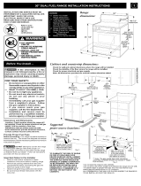
• A child or adult can tip the
range and be killed,
o Verify the anti-tip device has
been installed to floor or wall,
• Ensure the anti-tip device is re-engaged to floor
or wall when the range is moved,
• Do not operate the range without the anti-tip
device in place and engaged.
e Failure to follow these instructions can result in
death or serious burns to children and adults,
ii Range
leveling leg
\_ Anti-tip
: S-bracket
To check if the anti-tip bracket is installed properly, use
both arms to grasp the rear edge of the range back.
Carefully attempt to tilt range forward. When properly
installed, the range should not tilt forward.
ii
Refer to the anti-tip bracket installation instructions
ii
supplied with your range for proper installation.
Refer to your serial plate for
applicable agency certifications
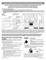
Clearances and Dimensions
Location: Check location where the ranqe will be installed.
Check for proper electrical and gas supply, and the stability
of the floor,
Dimensions that are shown must be used, Given
dimensions provide minimum clearance, Contact surface
must be solid and level,
t
48=1/2"
maximum
36+1/8"
/ .........
.......-_..... door
..... closed
...._ 44-5/8"
maximum
door
Provide Proper Fuel Type
Before proceeding: Your range isfactory preset to operate on
natural gas, If L,P, conversion is needed, contact your local
L,P, Gas provider for assistance,
The L.P. conversion kit may be located on the lower rear
back panel of the range, If no L,P, kit is provided, contact
your product dealer to obtain the correct L,P, conversion kit,
PN 316454928 RevA (1206)

IMPORTANT NOTE TO THE CONSUMER
• Keep these instructions with your Use & Care Guide
for future reference.
• As when using any appliance generating heat, there
are certain safety precautions you should follow. These
are listed in the Use & Care Guide, read it carefully.
• Be sure your range is installed and grounded properly
by a qualified installer or service technician.
• Make sure the wall coverings around the range can
withstand the heat generated by the range.
• To eliminate the need to reach over the surface
elements or burners, cabinet storage space directly
above the range should be avoided.
IMPORTANT NOTES TO THE INSTALLER
• Read all instructions contained in these installation
instructions before installing range.
• Remove all packing material from the oven
compartments before connecting the gas and electrical
supply to the range.
• Observe all governing codes and ordinances.
• Be sure to leave these instructions with the consumer.
IMPORTANT SAFETY INSTRUCTIONS
• Installation of this range must conform with local codes
or, in the absence of local codes, with the National
Fuel Gas Code ANSI Z223. l--latest edition when
installed in the United States.
• When installed in a manufactured (mobile) home,
installation must conform with the Manufactured Home
Construction and Safety Standard, Title 24 CFR, Part
3280 [formerly the Federal Standard for Mobile Home
Construction and Safety, Title 24, HUD (Part 280)] or,
when such standard is not applicable, the Standard
for Manufactured Home Installations, ANSI/NCSBCS
A225.1, or with local codes.
• Proper Installation--Be sure your appliance is properly
installed and grounded by a qualified technician in
accordance with the National Fuel Gas Code ANSI
Z223-latest edition, or in Canada CAN/CGA B149.1
and CAN/GGA B149.2, and the National Electrical
Code ANSI/NFPA No.70-1atest edition, or in Canada
CSA Standard C22.1, Canadian Electrical Code,
Part 1, and local code requirements. Install only
per installation instructions provided in the literature
package for this range.
• This range has been design certified by CSA
International. As with any appliance using gas and
generating heat, there are certain safety precautions
you should follow. You will find them in the Use & Care
Guide, read it carefully.
• Special instructions for appliances installed in the
State of Massachusetts: This appliance can only be
installed in the State of Massachusetts by a Massa-
chusetts licensed plumber or gas fitter. When using
a flexible gas connector, it must not exceed 3 feet
(36 inches) in length. A "T" handle type manual gas
valve must be installed in the gas supply line to this
appliance.
• Be sure your range is installed and grounded properly
by a qualified installer or service technician.
• This range must be electrically grounded in
accordance with local codes or, in their absence, with
the National Electrical Code ANSI/NFPA No. 70-
latest edition when installed in the United States. See
"Grounding Instructions" on page 7-9 in the Installation
Steps.
• Before installing the range in an area covered with
linoleum or any other synthetic floor covering, make
sure the floor covering can withstand heat at least
90°F above room temperature without shrinking,
warping or discoloring. Do not install the range over
carpeting unless you place an insulating pad or sheet
of 1/4-inch thick plywood between the range and
carpeting.
• Make sure the wall coverings around the range can
withstand the heat generated by the range.
• Do not obstruct the flow of combustion air at the oven
vent nor around the base or beneath the lower front
panel of the range. Avoid touching the vent openings
or nearby surfaces as they may become hot while the
oven is in operation. This range requires fresh air for
proper burner combustion.
• Do not store items of interest to children in the
cabinets above the range. Children could be seriously
burned climbing on the range to reach items.
• To eliminate the need to reach over the surface
burners, cabinet storage space above the burners
should be avoided.
• Adjust surface burner flame size so it does not extend
beyond the edge of the cooking utensil. Excessive
flame is hazardous.
• Do not use the oven as a storage space. This creates
a potentially hazardous situation.
• Never use your range for warming or heating the room.
Prolonged use of the range without adequate ventilation
can be dangerous.
• Do not store or use gasoline or other flammable vapors
and liquids near this or any other appliance. Explosions
or fires could result.
• Reset all controls to the "off" position after using a
programmable timing operation.
FORMODELSWITH SELF-CLEAN FEATURE:
• Remove broiler pan, food and other utensils before self-
cleaning the oven. Wipe up excess spillage. Follow the
cleaning instructions in the Use & Care Guide.
• Unlike the standard gas range, THIS COOKTOP IS NOT
REMOVABLE. Do not attempt to remove the cooktop.

Tools you will need
(Wear safety glasses when using tools):
For leveling legs and Anti-Tip Bracket:
• Adjustable wrench or channel lock pliers (Fig. 1).
• 1/4" & 5/16" Nutdriver or flat head screwdriver (Fig. 2).
• Electric drill & 1/8" dia. bit (5/32" Masonry drill bit if
installing in concrete (Fig. 3).
• Level (Fig. 4).
For gas supply connection:
• Pipe wrench (Fig. 5).
For burner flame adjustment:
• Phillips head and small blade-type screwdrivers (Fig. 6
and Fig. 7).
For gas conversion (LP/Propane or Natural):
• Open end wrench - 1/2" (Fig. 8).
Tools
Fig. 1
Fig. 2
Fig. 5
Fig. 6
Fig. 7
Fig. 3
Fig. 8
Fig. 4
Additional materials you may need:
• Anti-Tip Template (Fig. 9), Anti-Tip bracket, 2 mounting
screws (bracket and screws are supplied with range -
Fig. 10) and masking tape (Fig. 11).
• Pipe joint sealant that resists action of LP/Propane gas
(Fig. 12).
• Gas line manual shut-off valve (Fig. 13).
• 1/2" NPT 90° black pipe elbow (Fig. 14).
• A new flexible metal appliance conduit (1/2" NPT
x 3/4" or 1/2" I.D.) must be design certified by CSA
International (Fig. 15). Because solid pipe restricts
moving the range we recommend using a new flexible
conduit (48" MAXIMUM LENGTH)for each new
installation and additional reinstallations.
• Always use the (2) new flare adapters (1/2" NPT x 3/4"
or 1/2" I.D.) supplied with the new flexible appliance
conduit for connection of the range (Fig. 16).
• Power cord (40/50 ampere rated Cord Kit - 48"
MAXIMUM LENGTH - Fig. 17).
• 4 or 3 wire, 40/50 ampere rated wall receptacle and
mounting plate (Fig. 18).
• Copper electrical wiring and metal conduit (for hard
wiring installation only).
Materials
Fig. 9
Fig. 10
Fig. 11
Fig. 12
Fig. 13
Fig. 14
Fig. 15
Fig. 16
4 or 3 Wire Cord Kit
48"MAXIMUM LENGTH
Fig. 17
Fig. 18

To eliminate the risk of burns
or fire by reaching over
heated surface units, cabinet
storage space located above
the surface units should be
avoided. If cabinet storage
is to be provided, the risk
can be reduced by installing
a range hood that projects
horizontally a minimum of
5" beyond the bottom of the
cabinets.
Cabinet and countertop dimensions
• Check for wall and cabinet clearances where the range will be installed.
• Check the stability of the floor where the range will be installed.
• Check for proper electrical and gas supply.
Note: All dimensions provided are minimal unless otherwise stated.
18" 13"
Maximum
Minimum on depth for cabinets
either side of above ramge top
range
Minimum
30"
Cabinet
ig
Back Wall
Electric here
Fig. A
2=1/4"
Back Wall
Fig. B
Install a flush mount
240V 40/50 ampere
electrical wall outlet
in the shaded area.
• Do not seal the range to side cabinets.
• Do not pinch the power supply cord between the range
and the wall.
• If cabinet depth is greater than 25", the oven front
frame must extend beyond cabinet front by 1/2"
minimum.
All openings in the wall or floor where the range is
to be installed must be sealed.
This shaded floor
area is for thru the
floor connection of
gas pipe stub and
shut-off valve.
Fig. C
Add 1/2" NPT 90 °
black pipe elbow to
the gas supply pipe
stub and orient the
elbow as shown.
Note: The gas supply pipe stube and elbow assembly
centerline should not exceed 4" height form the floor.

Installation with cabinets and wall
.................
i i
Minimum clearance to
side wall on either side of .... '
range is 5"
wALL
i
i
i
i
i
i
i
i
i
i
Fig. D
Anti-tip installation
IMPORTANT SAFETY WARNING!
To reduce the risk of tipping of the range, the range must
be secured to the floor by properly installed anti-tip bracket
and screws packed with the range. Failure to install the
anti-tip bracket will allow the range to tip over if excessive
weight is placed on an open door or if a child climbs upon
it. Serious injury might result from spilled hot liquids or
from the range itself.
If range is ever moved to a different location, the anti-tip
brackets must also be moved and installed with the range.
Instructions are provided for installation in wood or cement
fastened to either the floor or wall. When installed to the
wall, make sure that screws completely penetrate dry wall
and are secured in wood or metal. When fastening to the
floor or wall, be sure that screws do not penetrate electrical
wiring or plumbing.
Anti-tip bracket installation
1. Place the Bracket Using the Template - Bracket
may be positioned on either the left or right side of the
range. Refer to Fig. 19, Fig. 20, and Fig. 22 to position
the bracket if template is not available.
2. Mark the floor or wall where left or right side of the
range will be located.
• If rear of range is against wall or no further than 1-1/4"
from wall when installed, you may use the wall or floor
mount method (Fig 19).
• For wall mount (Fig. 19), locate the bracket by placing
the back edge of the template against rear wall
and the side edge of template on the mark made
referencing the side of the range. Place bracket on
top of template and mark location of the screw holes
in wall. If rear of range is further than 1-1/4" from wall
when installed, attach bracket to the floor.
FASTEN BRACKET (WALL OR FLOOR MOUNTING)
-=1_1 14==1=1/4'' Max.
Leveling Leg -- i"-,
-Wall Mount
Wall Plate
\- \
Floor Mount p Bracket
Fig 19
• For floor mount (Fig. 20), locate
the bracket by placing back edge of the template
where the rear of the range will be located. Mark the
location of the screw holes shown in template.
If molding is installed and does not allow the bracket to
fit flush against wall, remove molding or mount bracket
to floor (Fig. 20).

,
Drill Pilot Holes & Fasten Bracket - Drill 1/8" pilot
hole where screws are to be located (Fig. 21). If
bracket is to be mounted to the wall, drill pilot hole at
an approximate 20° downward angle. If bracket is to
be mounted to masonry or ceramic floors, drill 3/16"
pilot hole 1-3/4" deep. The screws provided may be
used in wood or concrete material. Use 5/16" nut-
driver or flat head screwdriver to secure the bracket in
place.
Fig 21
4.
Level & Position Range - Level range by adjusting
the (4) leveling legs with a wrench. Note: A minimum
clearance of 1/8" is required between bottom of range
and leveling legs to allow room for bracket. Slide range
back into position (Fig. 22). Remove lower panel or
storage drawer to visually check that rear leveling leg
is inserted into and fully secured by the bracket. For
models with a warmer drawer or broiler compartment,
grasp the top rear edge of the range and carefully
attempt to tilt it forward.
Fig 22
5. Use a level to check your adjustments (Fig. 23).
Electrical connection requirements
3 and 4 - Wireelectrical walt receptacletypes and
recommended mounting orientation on wall
Required for new and remodeled
__ i _ _ installations
_ 4-Wire Wall receptacle (14-50R)
u
Allowed for existing installations
_i 3 Wire Wall
receptacle (10-50R)
Fig. 24
This appliance must be properly installed and grounded
by a qualified technician in accordance with the National
Electrical Code ANSI/NFPA No. 70 -- latest edition -- and
local electrical code requirements.
This appliance may be connected by means of permanent
"Hard Wiring" or "Power Supply Cord Kit."
When hard wiring, do not leave excess wire in range
compartment. Excess wire in the range compartment may
not allow the access cover to be replaced properly, and
could create a potential electrical hazard if wires become
pinched. Connect only as instructed under "WIRING
INSTRUCTIONS" in Step B of the Installation Steps. When
using flexible conduit or range cable use flex connector or
range cable strain relief (See Fig. 27 on page 7).
NOTE: Only use copper wire in connection to terminal
block.
MODELS REQUIRING POWER SUPPLY CORD KIT
RISK OF FIRE OR ELECTRICAL SHOCK MAY OCCUR IF
AN INCORRECT SIZE RANGE CORD KIT IS USED, THE
INSTALLATION INSTRUCTIONS ARE NOT FOLLOWED
OR STRAIN RELIEF BRACKET IS DISCARDED.
This appliance may be connected by means of a power
supply cord. Only a power supply cord kit rated at 125/250
volts minimum, and marked for use with ranges shall
be used. See chart (Fig. 28) for cord kit ampere rating
information. Cord must have either four (4) or three (3)
conductors (See Fig. 24). Terminals on end of wires
must be either closed loop or open-end spade lugs with
upturned ends. Cord must have strain relief clamp. See
Step B in Installation Steps for 4 or 3 - Wire connections.
Fig 23

[I_ DO NOT MAKE ANY ATTEMPT TO
OPERATE THE ELECTRIC IGNITION OVEN DURING
AN ELECTRICAL POWER FAILURE. RESETALL OVEN
CONTROLS TO "OFF" IN THE EVENT OF A POWER
FAILURE.
The electric ignitor will automatically re-ignite the oven
burnerwhen power resumes ifthe oven thermostat control
was left in the "ON" position.
When an electrical power failure occurs during use, the
surface burners will continue to operate.
During a power outage, the surface burners can be lit
with a match. Hold a lighted match to the burner, then
slowly turn the knob to the _:_ (lite) position. Use extreme
caution when lighting burners this way.
RANGE INSTALLATIONS STEPS
Access the terminal block
The rear access cover must be removed. To remove, loosen
center screw (one screw) and remove access cover. The
terminal block will then be accessible (See Fig. 25).
Rerno_ve
Access
Cover to install
Power Cord.
Replace after
installation.
Fig. 25
Rear
of Range
1=1/8" Dia. 7/8" Dia.
Knockout Hole
(See Chart) (See Chart)
Mounting
Plate
1=3/8" Pocket
Hole for Cable
(See Chart) Mounting Plate
Fig. 26
Range Connection Opening Size Chart
Supply cord kit ampere rating information.
See serial plate on range for
kilowatt (kw) rating
120/240 Volts
8.8-16.5 kw
16.6-22.5 kw
Fig. 27
120/208 Volts Cord Kit
Ampere
Rating
7.9-12.5 kw 40/50
Amp
12.6-18.5 kw 50Amp
Diameter (inches)
of range conenction
opening
Cord kit Perma-
nent
wiring
1-1/8 in1-3/8 in
1-3/8 in 1-3/8 in
Power
Cord Strain
Relief Bushing
Separate Power Cord
Strain Relief Bushing
before installation
Fi0.28

_ 4-wire connection instructions
Before wiring the range review the suggested power
source location drawing in Fig. B. If connecting to a 4-Wire
electrical system (new branch-circuit or mobile home
requires 4-Wire connection):
Power cord instructions
1. Follow the manufacturer's installation instructions
supplied with the strain relief and install (See Fig. 28).
2. Insert the end connectors for Line 1, Line 2 and
Neutral and tighten securely to the terminal block.
IMPORTANT NOTE: DO NOT LOOSEN the factory
installed nut connections which secure the range
wiring to the terminal block. Electrical failure or loss
of electrical connection may occur if these 3 nuts are
loosened or removed.
3. You must disconnect the ground strap. Remove the
factory installed ground screw and plate to release the
copper ground strap from the frame of the appliance.
Cut and discard the copper ground strap and plate.
KEEP the ground screw.
4. Connect the ground wire (Green) lead with the eyelet
to the frame of the appliance with the ground screw
using the same hole in the flame where the ground
screw was originally installed (See Fig. 29).
5. Make sure all screws are tightened securely and
replace the rear access cover (See Fig. 25).
4-Wire Connection
3 Factory installed connections
(DO NOT LOOSEN)
Terminal
block
Connect
line 1
here
Cut ground
strap,
ground strap
& ground plate
Connect g
insulated copper
ground wire with
ground screw here
NOTES:
install strain=relief
bushing, Center or white
wire must always be
attached to the center
terminal on block
Fig. 29
Connect
neutral
(white or
center) here
Connect
line 2
here
OR _ 3-wire connection instructions
_ (for existing installations ONLY)
Power Cord Instructions
1. Follow the manufacturer's installation instructions
supplied with the strain relief and install (See Fig. 28).
2. Insert the end connectors for Line 1, Line 2 and
Neutral and tighten securely to the terminal block (See
Fig. 30).
IMPORTANT NOTE: DO NOT LOOSEN the factory
installed nut connections which secure the range
wiring to the terminal block. Electrical failure or loss
of electrical connection may occur if these 3 nuts are
loosened or removed.
3. Make sure all connections are tightened securely and
replace the rear access cover (See Fig. 25).
3-Wire Connection
3 Factory installed connections
Connect (DO NOT LOOSEN) Connect
line 1 neutral
here (white or
center) here
Terminal
block
Ground strap
Ground screw
& ground plate
NOTES:
Install strain=relief
bushing. Center or white
wire must always be
attached to the center
terminal on block
Fig. 30
3-Wire Connections ONLY - Grounding
Instructions
A ground strap is installed on this range which connects
the center terminal of the terminal block (neutral) to the
range chassis. The ground strap is connected to the range
by the center, lowest screw (See Fig. 30). The ground
strap must not be removed unless national or local codes
do not permit use of ground strap.
NOTE: If the ground strap is removed for any reason, a
separate ground wire must be connected to the separate
ground screw attached to the range chassis and to an
adequate ground source.

3 & 4-Wire permanent connections ONLY
IMPORTANT: 3 - Wire permanent connection - follow
Steps 1, 2 and 5 below.
IMPORTANT: 4 - Wire permanent connection - follow
Steps 1 thru 5 below.
Before wiring the range, review the suggested power
source location drawings in Fig. A and B on page 4. If
connecting to a 4-Wire electrical system (new branch-
circuit or mobile home requires 4-Wire connection):
,
,
3 and 4 - Wire Permanent Connections - Follow the
manufacturer's installation instructions supplied with
the strain relief and install (See Figre 28).
3 and 4 - Wire Permanent Connections - Strip
insulation away from the ends of the permanent wiring
for Line 1, Line 2, Neutral (also strip ground wire on
4-Wire Connections). Tighten all 3 wire leads to the
terminal block (follow wire locations shown in Fig. 31).
FOR 3 & 4=Wire Permanent Connections
!
Tightenall 3 Terminal
wire leads block
Line 1 Neutral
Line2
plate
screw
Ground strap
Fig. 31
NOTE: Non-terminated field wire compression
connections must be set at approximately 22in./Ibs.
Always use 10 ga. wire or larger.
IMPORTANT NOTE: DO NOT LOOSEN the factory
installed nut connections which secure the range
wiring to the terminal block. Electrical failure or loss
of electrical connection may occur if these 3 nuts are
loosened or removed.
NOTE: For 3-Wire Permanent Connections skip Steps
3 and 4 and continue with Step 5.
, 4-Wire Permanent Connection ONLY - Disconnect
the ground strap. Remove the factory installed ground
screw & plate to release the factory installed copper
ground strap from frame of the appliance. Cut and
discard the copper strap from the terminal block. KEEP
the ground screw, ground plate and go to Step 4.
GROUND
PLATE ===_"
A
GROUND
SCREW
Fig. 32
GROUND
4=.
WIRELEAD
PROPER
GROUND FOR
4-WIRE
PERMANENT
CONNECTION
4. 4-Wire Permanent Connection ONLY- Connect the
ground wire lead (Green) to the frame of the appliance
using the ground screw & plate as shown in Fig. 32.
Be sure to install using the same hole in the frame
where the ground screw was originally installed.
5. 3 and 4 -Wire Permanent Connections - Make sure
all connections are tightened securely and replace the
rear access cover (See Fig. 25).
Provide an adequate gas supply.
This range is pre-set to operate on 4" natural gas manifold
pressure. The Pressure Regulator is connected to the
manifold and MUST be connected in series with the gas
supply line (See Fig. 33 on page 10).
Care must be taken during installation of range not to
obstruct the flow of combustion and ventilation air. The gas
supply line should be 1/2" or 3/4" I.D.
For proper operation, the maximum inlet pressure to the
regulator should be no more than 14 inches of water
column pressure. The inlet pressure to the regulator must
be at least 1 inch greater than regulator manifold pressure.
Examples: If regulator is set for natural gas 4 inch manifold
pressure, inlet pressure must be at least 5 inches;
if regulator has been converted for LP/Propane gas
10 inch manifold pressure, inlet pressure must be at least
11 inches. Leak testing of the appliance shall be conducted
according to the instructions in Step E.

Seal the wall and floor openings
Seal any openings in the wall behind the range and in the
floor under the range after gas supply line is installed. See
Figures A, B, C and D on pages 4 and 5.
Connect the range to the gas supply
Before connecting gas supply to range, review the
suggested power source location drawings (See Figures
A, B, and C on page 4). To prevent leaks apply pipe joint
sealant on all male (outside) pipe threading. The Pressure
Regulator can be found mounted to the lower left rear of
range (See Fig 32). To install the gas supply:
1.) Install 1/2" NPT 90° Black Pipe Elbow to the gas supply
pipe stub (See Fig 33)
2.) Install an external gas Shut-Off Valve (manual) to gas
supply line in an easily-accessible location outside of the
range. Be sure you know how and where to shut-off the
gas supply to the range (See Fig 33).
3.) Install Flare Adapter* to gas Pressure Regulator
(See Fig. 33).
Pressure
Regulator
Location and
Installation
of
Gas
Supply
Flexible Appliance
Conduit
.... ,@
t _' Flare Manual 1/2 NPT
Pressure _ ...........AAdap tor Shutoff Black Pipe
Regulator _ @ | Valve 90 Elbow
Hare ........ _ _ _ _ _
Adaptor '
ootjLI
Off
Fig. 33
*NOTE: Be sure to use the 2 Flare Adapters supplied with
the Flexible Conduit Kit.
[I'_112__ Do not use a flame to check for gas leaks.
Checking Manifold Gas Pressure:
Disconnect the range and its individual shut-off valve from
the gas supply piping system during any pressure testing
of that system at test pressures greater than 14" of water
column pressure (approximately 1/2" psig). The appliance
must be isolated from the gas supply piping system by
closing its individual manual shut-off valve during any
pressure testing of the gas supply piping system at test
pressures equal to or less than 14" of water column
pressure (approximately 1/2" psig).
If it should be necessary to check the manifold gas
pressure, connect manometer (water gauge) or other
pressure device to the top burner right rear orifice. Using
a rubber hose with inside diameter of approximately 1/4,"
hold tubing down tight over orifice. Turn burner valve
on. For an accurate pressure check have at least two
(2) other top burners burning. Be sure the gas supply
(inlet) pressure is at least one inch above specified range
manifold pressure. The gas supply pressure should never
be over 14" water column. When properly adjusted for
Natural Gas the manifold pressure is 4" (For LP/Propane
Gas the manifold pressure is 10").
Read the electrical connection
details below. Plug the range into the
wall receptacle.
Before servicing, disconnect electrical
supply at circuit breaker, fuse or Power Cord.
PLEASE READ CAREFULLY! For
personal safety, this product must be properly grounded.
Do not allow the Pressure Regulator to turn
on pipe when tightening fittings.
4.) Attach flexible Appliance Conduit to Flare Adapter on
Pressure Regulator (See Fig 33).
5.) Install 2nd Flare Adapter* to external manual Shut-Off
Valve (See Fig 33).
6.) Attach flexible Appliance Conduit to Flare Adapter on
Shut-Off Valve (See Fig 33).
7.) After making these connections, check for gas leaks.
Turn the gas supply on to the range and use a liquid leak
detector at all joints and conduits to check for leaks in
the system.
10

Carefully slide range into cabinet
opening.
Carefully slide range into cabinet opening while inserting
rear leveling leg into and FULLY ENGAGING THE ANTI-
TIP BRACKET (See Fig. 22 on page 6). Make sure that
the flexible appliance conduit and the power cord folds into
the remaining open floor area behind the range warmer
or storage drawer. Make sure that the flexible appliance
conduit does not become pinched or kinked. Pre-shape the
flexible appliance conduit and power cord if necessary to
insure that the range slides into cabinet opening properly.
Be sure to check level of the range by placing a level
horizontally on an oven rack (See Fig. 23 on page 6).
Surface burner heads, cap & grates
It is very important to make sure that all of the surface
burner heads, surface burner caps and surface burner
grates are installed correctly.
Your appliance was shipped with the burner heads and
burner caps assembled in the correct locations (See
Fig. 34).
Should you need to re-install the burner caps please refer
to the Use & Care guide for more information.
REMEMBER-- DO NOTALLOW SPILLS, FOOD, CLEANING
AGENTS ORANY OTHER MATERIAL TO ENTER THE GAS
ORIFICE HOLDER OPENING.
Always keep the Burner Caps and Burner Heads in place
whenever the surface burners are in use.
Check electric ignition of surface burners
Operation of electric igniters should be checked after range
and supply line connectors have been carefully checked for
leaks and range has been connected to electric power.
a. To check for proper ignition, push in and turn a surface
burner knob counterclockwise to the LITE position
(see Fig. 35). You will hear the igniter sparking.
b. The surface burner should ignite when gas is available
to the burner. Purge air from supply lines by leaving
knob in the LITE position until burner ignites. Each
burner should light within four (4) seconds in normal
operation after air has been purged from supply lines.
c. Visually check that burner has a flame. Once the
burner ignites, the control knob should be turned out of
the LITE position.
d. Try each surface control knob separately until all
surface burners have been checked. Each burner
location is equipped with a separate electrode.
Fig. 35
Fig. 34
1. 5,000 BTU Simmer Burner.
2. 10,000 BTU Bridge Burner.
3. 9,500 BTU Power Burner.
4. 12,000 or 14,200 BTU Power Burner.
5. 18,000 BTU Double Burner (some models).
11

_ Adjust the "LOW" setting of surface
burner valve (for linear flow valves only)
1. Push in and turn knob to (lite) until burner ignites.
2. Push in and quickly turn knob to LOWEST
POSITION.
3. If burner goes out, reset control to OFF and set to
low flame again.
4. Remove the burner control knob.
, Insert a thin-bladed screwdriver into the hollow
valve stem and engage the slotted screw inside
(See Fig. 36). Flame size can be increased or
decreased with the turn of the screw. Turn coun-
terclockwise to increase flame size. Turn clockwise
to decrease flame size.
Fig. 36
After installation is complete, make all
controls are left in the OFF position.
Care, cleaning and maintenance
Refer to the Use & Care Guide for cleaning instructions.
If removing the range is necessary for cleaning or
maintenance, shut off the gas supply. Disconnect the
gas and electrical supply. If the gas or electrical supply
is inaccessible, lift the range slightly at the front and pull
out away from the wall. Pull only as far as necessary to
disconnect the gas and electrical supply. Finish removing
the range for servicing and cleaning. Reinstall in reverse
order making sure to level the range and check gas
connections for leaks. See anti-tip instructions for proper
anti-tip anchoring instructions.
Before you call for service
Refer to the Use & Care Guide for cleaning instructions.
If removing the range is necessary for cleaning or
maintenance, shut off the gas supply. Disconnect the
gas and electrical supply. If the gas or electrical supply
is inaccessible, lift the range slightly at the front and pull
out away from the wall. Pull only as far as necessary to
disconnect the gas and electrical supply. Finish removing
the range for servicing and cleaning. Reinstall in reverse
order making sure to level the range and check gas
connections for leaks. See page 5 and 6 of this document
for proper anti-tip anchoring instructions.
Model and serial number location
The Serial Plate is located on the right-hand surface of the
oven front frame at the storage or warmer drawer; or the
lower panel area (See Fig. 37).
I
i! iii ii_i_ii ii ii ii ii ii ii ii iii
Fig. 37
When ordering parts for or making inquires about your
range, always be sure to include the model and serial
numbers and a lot number or letter from the Serial Plate
on your range. The Serial Plate will also inform you of the
rating of the burners, the type of fuel and the pressure the
range was adjusted for when it left the factory.
12

LA INSTALAClON Y EL SERVIClO DEBEN SER EFECTUADOS POR UN INSTALADOR CALIFICADO.
IMPORTANTE: CONSERVE ESTAS INSTRUCClONES PARA USO DEL INSPECTOR LOCAL DE ELECTRIClDAD.
LEA Y CONSERVE ESTAS INSTRUCClONES PARA REFERENClA FUTURA.
Consulte la placa de serie
para las certificaciones de las
agencias correspondientes
Si no se sigue estrictamente
la informacibn de este manual, se puede
producir un incendio o una explosibn
causando daSos materiales, lesiones
corporales o fatales.
PARA SU SEGURIDAD:
m No almacene ni use gasolina u
otros liquidos o vapores inflam-
ables cerca de este o cualquier
otro artefacto.
SI SIENTE OLOR A GAS:
• No trate de encender el artefacto.
• No toque ningun interruptor elec-
trico; no use ningun telefono en
su edificio.
• Llame inmediatamente a su prov-
eedor de gas desde un telefono
vecino. Siga las instrucciones del
proveedor de gas.
• Si no puede comunicarse con su
proveedor de gas, Ilame al depar-
tamento de bomberos.
La instalacion y el servicio deben
ser efectuados por un instalador o
tecnico calificado o por el provee-
dor de gas.
Riesgo de volca miento
- Unnifio oadulto puedevolcarlaestufay
acabar muerto.
• Verifique que se haya instalado el
dispositivo antivuelco en el piso o en la
-- pared.
- AsegQrese de que el dispositivo antivuelco se haya reacoplado
cuando mueva la estufa sobre el piso o a la pared,
- No utilice la estufa sin el dispositivo antivuelco instalado y
acoplado.
- Sinose siguen estas instrucciones,se puede provocar la muerte
o quemaduras graves en niSos y adultos,
n,T°renl'_dorde
,0es u 0
Para verificar si el soporte antivuelco est_ instalado
correctamente, sostenga el borde trasero de la parte
trasera de la estufa usando ambos brazos. Intente indinar
la estufa hacia adelante con cuidado. Si est_ instalada
correctamente, la estufa no deberia inclinarse hacia
adelante.
Consulte las instrucciones de instalaci6n del soporte
antivuelco proporcionadas con la estufa para instalarlo
adecuadamente,
Espacios Libres y Dimensiones
Ubicaci6n - Revise el luqar donde sera instalada la estufa.
Verifique el suministro de energia electrica y la estabilidad
del piso.
Es esencial que se usen las dimensiones que se
muestran. Las dimensiones indicadas proveen los
espacios libres minimos. La superficie de contacto debe
ser firme y nivelada.
t
48-1/2"
maximum
Proporcione el tipo de combustible adecuado
Antes de proceder: Su estufa fue ajustada en la fabrica para
utilizar gas natural. Si necesita realizar una conversi6n a
gas LP, Ilame a su distribuidor local de gas LP para obtener
asistencia.
Es posible que el kit de conversi6n a gas LP se encuentre
en el panel inferior trasero de la estufa. Si no se incluye un
kit de gas LP, p6ngase en contacto con su distribuidor de
electrodomesticos para obtener el kit de conversi6n a gas
LP adecuado.
36_+1/8"
29-7/8".-
maximum
door
closed
/fl
44-5/8"
maximum
doer
PN 316454928 RevA (1206)

AVISO IMPORTANTE AL CONSUMIDOR
• Mantenga estas instrucciones con su Guia de Uso y
Cuidado para referencia futura.
• AI igual que con cualquier electrodomestico que
genere calor, existen ciertas precauciones de
seguridad que usted debe seguir. Tales precauciones
se encuentran en la Guia de Uso y Cuidado, leala
atentamente.
• AsegQrese de que la estufa est6 bien instalada y
puesta a tierra en forma debida por un instalador
calificado o un t6cnico de servicio.
• AsegQrese de que el revestimiento de la pared
alrededor de la estufa puede resistir el calor generado
por la estufa.
• Para eliminar la necesidad de tener que pasar
sobre los elementos o quemadores superiores, se
recomienda no instalar armarios directamente arriba
de la cubierta de la estufa.
NOTAS IMPORTANTES PARA EL
INSTALADOR
• Lea todas las instrucciones indicadas en estas
instrucciones de instalaci6n antes de instalar la estufa.
• Saque todo el material de empaque del
compartimiento del horno antes de conectar el
suministro de gas y de electricidad a la estufa.
• Observe todos los c6digos y reglamentos pertinentes.
• AsegQrese de dejar estas instrucciones con el usuario.
INSTRUCCIONES IMPORTANTES DE
SEGURIDAD
• La instalaci6n de esta estufa debe ser de acuerdo con
los c6digos locales o, en ausencia de c6digos locales,
con el C6digo Nacional de Gas Combustible ANSI
Z223.1 - Qltima edici6n cuando sea instalado en los
Estados Unidos.
• Cuando la estufa sea instalada en una casa m6vil
(prefabricada), lainstalaci6n debe cumplir con las normas
vigentes de Manufactured Home Construction and Safety
Standard (Normas de Construcci6n y Seguridad de Casas
Prefabricadas, Titulo 24 CFR, Parte 3280 (anteriormente
denominada Normas Federales para la Construcci6n y
Seguridad de Viviendas M6viles, Titulo 24, HUD (Parte
280) o, cuando tales normas no corresponden, se
deben cumplir las Normas para Instalaciones en Casas
Prefabricadas, ANSI/NCSBCS A225.1 o los c6digos
locales.
• El dise_o de esta estufa ha sido certificado por la CSA
International. AI igual que con cualquier artefacto que use
gas ygenere calor, se deben seguir ciertas precauciones
de seguridad. Las encontrar& en la Guia de Uso y
Cuidado, 16ala atentamente.
• AsegQrese de que su estufa sea instalada y puesta a
tierra en forma debida por un instalador calificado o un
t6cnico de servicio.
• Esta estufa debe ser puesta a tierra electricamente
de acuerdo con los c6digos locales o, en ausencia de
ellos, con el C6digo EI6ctrico Nacional ANSI/NFPA No.
70 - Qltima edici6n cuando es instalada en los Estados
Unidos. Vea las "lnstrucciones para la Puesta a Tierra"
en la p&gina 20 y 21 de los Pasos de la Instalaci6n de
la Estufa.
• Antes de instalar la estufa en un &rea que est6 cubierta
con lin61eoo con cualquier otro revestimiento sint6tico de
piso, asegQrese de que el revestimiento del piso pueda
soportar calor de por Iomenos 90°F sobre la temperatura
ambiente sin encogerse, combarse o descolorarse.
No instale la estufa sobre una alfombra a menos que
usted coloque un cojin aislante o una hoja de madera
contrachapada de 1/4" de grosor entre la estufa y la
alfombra.
• AsegQrese de que los revestimientos de la pared alrededor
de la estufa puedan soportar el calor generado por la
estufa.
• No obstruya el flujo del aire de combusti6n en la ventilaci6n
del horno ni alrededor de la base ni debajo del panel
delantero inferior de la estufa. Evite tocar las aberturas
de ventilaci6n o las superficies cercanas pues pueden
calentarse cuando el homo est& en funcionamiento.
Esta estufa necesita aire fresco para una combusti6n
adecuada de los quemadores.
• No guarde articulos que interesen a los ni_os en los
armarios que est6n arriba de la estufa. Los ni_os pueden
quemarse seriamente si se trepan a la estufa para
alcanzar articulos.
• Para eliminar la necesidad de alcanzar articulos pasando
sobre los quemadores, se debe evitar colocar armarios
de almacenamiento sobre los quemadores.
• Ajuste el tama_o de la llama del quemador superior
de manera que no se extienda m&s all& del borde del
utensilio de cocina. Una llama excesiva es peligrosa.
• No use el homo como espacio para almacenamiento.
Esto crea una situaci6n potencialmente peligrosa.
• Nunca use este artefacto para calentar o calefaccionar la
habitaci6n. El uso prolongado de la estufa sin ventilaci6n
adecuada puede ser peligroso.
• No almacene ni use gasolina ni otros vapores o liquidos
inflamables cerca de este o de cualquier otro artefacto.
Se pueden producir explosiones o incendios.
• Vuelva a colocar todos los controles en la posici6n
"OFF" despues de usar una operaci6n programable con
temporizador.
PARA LOS MODELOS CON LA
CARACTERISTICA DE AUTOLIMPIEZA:
• Saque la asadera, los alimentos y otros utensilios
antes de efectuar la autolimpieza del horno. Limpie
los derrames. Siga las instrucciones de limpieza
indicadas en la Guia de Uso y Cuidado.
• A diferencia de una estufa a gas convencional, ESTA
CUBIERTA NO SE PUEDE SACAR. No trate de sacar
la cubierta.

Herramientas y Materiales Necesarios
(Cuando trabaje con herramientas use lentes protec-
tores):
Para los tornillos niveladores y soporte antivuelco:
Llave ajustable o pinzas ajustables (Fig. 1).
• Llave de tuerca de 1/4" y 5/16" o destornillador de
punta plana (Fig. 2).
• Taladro el6ctrico y broca de 1/8" de diam. (broca para
taladro de mamposteria de 5/32" siesta instalando
en concreto) (Fig. 3).
• Nivel (Fig. 4)
Para la conexi6n al suministro del gas:
• Llave de tubo (Fig. 5).
Para ajustar la llama del quemador:
• Destornillador Phillips y destornilladores de punta
plana (Figs. 6 y 7).
Para conversi6n del gas (Gas propano/G.L.R):
• Llave de boca abierta - 1/2" (Fig. 8).
Materiales adicionales que usted necesitar&:
• Plantilla del soporte antivuelco (Fig. 9), 2 tornillos de
montaje (el soporte y los tornillos son suministrados
con la estufa - Fig. 10) y cinta adhesiva (Fig. 11).
• Compuesto sellador de juntas resistente al gas G.L.P./
Propano (Fig. 12).
• Llave de cierre de la tuberia del gas (Fig. 13).
• Codo de tuberia negro de ½" NPT 90° (Fig. 14).
• Un conducto nuevo para artefacto de metal flexible
(1/2" NPT x 3/4" o 1/2" de D.I.) certificado por CSA
International. Debido a que la tuberia s61ida restringe
la movilidad de la estufa, recomendamos que use un
conducto nuevo flexible (LARGO MAXIMO: 48") para
cada nueva instalaci6n y reinstalaciones adicionales.
• Siempre use los (2) adaptadores de uni6n abocinados
nuevos (1/2" NPT x 3/4" o 1/2" de D.I.) suministrados
con el nuevo conducto flexible de artefacto para con-
exi6n de la estufa (Fig. 16).
• Cable electrico (Juego de Cable para 40/50 amperios -
LARGO MAXlMO: 48"- Fig. 17).
• Tomacorriente mural y placa de montaje, tetra o trifilar,
para 40/50 amperios (Fig. 18).
• Alambre electrico de cobre y tubo de metal (para in-
stalaci6n con cables permanentes solamente).
Herramientas
Fig. 1
Fig. 2
Fig. 5
Fig. 6
Fig. 7
Fig. 3
Fig. 8
Fig. 4
Materiales
Fig. 9
Fig. 15
Fig. 10 Fig. 16
LARGO MAXlMO: 48"
Fig. 12
Fig. 13
Fig. 14
Fig. 17
Fig. 18

Afin de eliminar el riesgo de
quemaduras o incendio cuando
se pasa sobre los elementos
superiors calientes para
alcanzar los armarios, se debe
evitar instalar armarios arriba
de la cubierta. Si se provee
espacio para almacenamiento
en tal lugar, se puede reducer
el riesgo instalando una
campana extractora que
proteja horizontalmente un
minimo de 5" mas alia de la
parte inferior de los armarios.
Dimensiones del gabinete y de la cubierta:
• Verifique el espacio libre entre las paredes y el gabinete del lugar donde se
instalara la estufa.
• Verifique la estabilidad del piso donde se instalara la estufa.
• Verifique el suministro electrico y de gas.
Nota: Todas las dimensiones estan en la minima Iongitud, esto si no se
menciona alguna excepci6n.
18" 13" Altura minima
Profundidad ma.xima de desde la
Minimo en los armarios arriba de cubierta a los
cualquier lado de la la cubierta de la estufa armarios
estufa
l
Fig. A
i:i_iii
Ubicaciones sugeridas para la
alimentacibn el_ctrica
30"
Ancho
de la
abertura
para el
gabinete
ParedTrasera
Surqinistr0el0ctricoaqui
2=1/4"
ParedTrasera
Fig. B
En esta area rayaka
instale un
tomacorriente el@trico
mural embutido de
240V 40/50 amperios.
• No selle la estufa a los armarios laterals.
• No apriete el cable el @ctricoentre la estufa y la pared.
• Si la profundidad del gabinete es superior a 25",
el marco delantero del horo debe extenderse por
Io menos ½" m as all a de la parte delantera del
gabinete.
Se deben sellar todas las aberturas de la pared o del
piso donde se instale la estufa.
ra C [................
En esta area rayada
en el piso es para la
instalaci 6n a trav @s
del piso del tubo
corto del gas de lab
Alvula de cierre.
Agregue un codo de
tuberia negro de 1/2"
NPT 90 al tubo corto
del suministro del gas
y dirija el codo como
se muestra.
Fig.
Max.
Nota: La linea central del conjunto del tubo corto del
gas y del codo no dibe estar a m &s de 4: de altura
desde el suelo.
C

Instalacion con armarios y pared
ii ii
Distancia milnima a la
pared lateral a ambos
lados de la estufa: 5".
i
i
i
i
/ ....... .
i
Fig. 13
:iiii_i_'i'lli?
Instalacion del Soporte Antivuelco
iADVERTENCIA DE SEGURIDAD
IMPORTANTE!
Para reducir el riesgo de que la estufa se vuelque,
es necesario asegurarla al piso instalando el soporte
antivuelco y los tornillos suministrados con la estufa. Si no
se instala el soporte antivuelco, la estufa se puede volcar
si un niSo se sube a ella. Se pueden ocasionar lesiones
graves causadas por los liquidos calientes derramados o
por la estufa misma.
Si la estufa es movida a otro lugar, el soporte antivuelco
debe tambi6n ser movido e instalado en la estufa.
Las instrucciones son adecuadas para instalaci6n en
pisos de madera o cemento sujeto ya sea al piso o la
pared. Cuando se instala en la pared, asegQrese de
que los tornillos penetren completamente en el drywall
y que est6n asegurados en madera o metal. Cuando
se asegura al piso o en la pared, asegQrese de que los
tornillos no penetren ningQn cableado electrico o plomeria.
Instrucciones de Instalacibn para el
Soporte Antivuelco
1. Ubique el soporte utilizando la plantilla - El soporte
puede ser instalado ya sea en el lado izquierdo o
derecho de la estufa. Consulte desde la Fig. 19, 20,
y 22 para colocar el soporte si no se dispone de la
plantilla.
2. Marque el piso o la pared donde se colocara el
lado izquierdo o derecho de la estufa.
• Si la parte trasera de la estufa sera colocada contra la
pared o a no mas de 1-1/4"de la pared cuando ya est6
instalada, usted puede usar el metodo de instalaci6n
en el piso o en la pared (Fig. 19).
• Para montaje en la pared (Fig. 19), ubique la plantilla
colocando el borde trasero de la plantilla contra la
pared trasera y el borde lateral de la plantilla en la
marca hecha indicando el lado de la estufa. Coloque
el soporte sobre la plantilla y marque la ubicaci6n de
los agujeros de los tornillos en la pared. Si la parte
trasera de la estufa esta a mas de 1-1/4" de la pared
cuando ya esta instalada, instale el soporte en el piso.
SOPORTE DE FIJACION
(INSTALACION EN LA PARED O EL PISO)
--_1 I_-- 11/4"(3cm)
Pata -- m&x.
niveladora
• Instalaci6n
en la pared
Instalaci6n
en el piso
Fig 19
Larguero
\
\ _/ j,
Soporte antivuelco
• Para montaje en el piso (Fig. 20), ubique el soporte
colocando el borde trasero de la plantilla donde
quedara ubicada la parte trasera de la estufa. Marque
la ubicaci6n de los agujeros de los tornillos mostrados
en la plantilla.
• Si tiene moldura instalada y 6sta no permite que el
soporte quede a ras contra la pared, retire la moldura
o instale el soporte en el piso (Fig 20).
SOPORTE DE FIJACI(SN
(L)NICAMENTE PARA INSTALACION EN EL PISO)
-4
Pata -- de 1 1/4"
niveladora (3 cm)
i _ Pared
i i
Instalaci6n _;
en el piso
Soporte antivuelco
Fig 20

3. Requerimientos Electricos
Taladre agujeros pilotos e instale el soporte -
Taladre un agujero piloto de 1/8" donde se van a
instalar los tomillos (Fig. 21). Si el soporte va a set
instalado en la pared, taladre un agujero piloto en
un angulo descente de aproximadamente 20 °. Si el
soporte va a set instalado en pisos de mamposteria
o de ceramica, taladre un agujero piloto de 3/16" y
1-3/4" de profundidad. Los tornillos provistos pueden
ser usados en materiales de madera o concreto. Use
una Ilave de tuerca de 5/16" o un destornillador de
punta plana para asegurar el soporte en su lugar.
Fig 21
,
Nivele y ubique la estufa - Nivele la estufa ajustando
los cuatro (4) tomillos niveladores con una Ilave. Nota:
Se debe dejar un espacio libre minimo de 1/8" entre
la parte inferior de la estufa y los tornillos niveladores
a fin de dejar espacio para instalar el soporte (Fig.
22). Deslice la estufa de nuevo a su lugar. Retire el
panel inferior o la gaveta de almacenamiento para
verificar visualmente si el tornillo nivelador trasero
esta insertado y firmemente asegurado pot el soporte.
Para los modelos con un compartimiento calefactor
o compartimiento de asador, sujete la estufa desde
el borde superior trasero y trate de inclinarla hacia
adelante cuidadosamente.
Fig 22
5. Use un nivel para verificar sus ajustes (Fig. 23).
Tipos de tomacorrientes murales electricos trifilares o
tetrafilares y orientaci6n recomendada de montaje en la pared
Requerido para instalaciones
nuevas y remodeladas
Tomacorriente Mural Tetrafilar
(14-50R)
Permitido para instalaciones
existentes
Tomacorriente Mural Tetrafilar
(10-50R)
Fig. 24
Este artefacto debe ser instalado y puesto a tierra en
forma correcta por un t6cnico calificado de acuerdo con
el C6digo Nacional de Electricidad ANSI/NFPA No. 70 --
Oltima edici6n -- y los requerimientos del c6digo local de
electricidad.
Este artefacto debe ser conectado mediante "cableado
permanente" o el "Juego de Cable de Alimentaci6n
EI6ctrica."
Cuando use cable, no deje el exceso de cable en el
compartimiento de la estufa. El exceso de alambre en el
compartimiento de la estufa puede impedir que la tapa de
acceso sea reinstalada en forma debida y podria crear un
riesgo electrico potencial si los alambres son apretados.
Conecte solamente como se indica en la secci6n
"INSTRUCClONES PARA EL CABLEADO" en el Paso B
de los Pasos de la Instalaci6n. Cuando use tubo flexible
o cable de estufa, use sujetacable de estufa o conector
flexible (Ver Fig. 27 en la pagina 7).
NOTA: Use solamente alambre de cobre en la conexi6n al
tablero de bornes.
Modelos que requieren el Juego de Cable
de Alimentaci6n Electrica
PUEDE OCURRIR RIESGO DE INCENDIO O CHOQUE
ELECTRICO SI SE USA UN JUEGO DE CABLE DE
ESTUFA DE CALIBRE INCORRECTO, SI NO SE SIGUEN
LAS INSTRUCClONES DE INSTALAClON O SI NO SE
USA EL SOPORTE DEL SUJETACABLES.
Este artefacto puede ser conectado mediante un cable de
alimentaci6n electrica. Se debe usar solamente un juego
de cable de alimentaci6n electrica para 125/250 voltios
minimo y marcado para uso con estufas. Vea la tabla
(Figura 29) para la informaci6n sobre la intensidad nominal
del juego de cable. El cable debe tener ya sea cuatro (4)
o tres (3) conductores (Ver Fig. 28). Los bornes en los
extremos de los cables deben ser ya sea en bucle cerrado
o terminales de horquilla con los extremos girados hacia
arriba. El cable debe tener abrazadera para sujetacable.
Ver Paso B en los Pasos de la Instalaci6n para conexiones
con cables tetrafilares o trifilares.
Fig 23

NO INTENTE USAR EL HORNO
DE ENCENDIDO ELECTRICO DURANTE UNA
INTERRUPClON DE LA CORRIENTE ELECTRICA.
COLOQUE TODOS LOS CONTROLES EN LA
POSlClON "OFF" (APAGADO) EN CASO DE UNA
INTERRUPClON DE LA CORRIENTE ELECTRICA.
El encendedor electrico volver_ a encender
autom_ticamente el quemador del horno cuando se
restaure la corriente electrica si es que el control del
termostato del horno se dej6 en la posici6n "ON"
(ENCENDIDO).
Cuando ocurre una interrupci6n de la corriente
electrica durante el uso, los querradores superiores
continean funcionando.
Durante una interrupci6n de la corriente electrica,
los quemadores superiores pueden ser encendidos
con un f6sforo. Sujete un f6sforo encendido cerca
del quemador, luego gire lentamente la perilla a
la posici6n "LITE". Tenga mucho cuidado cuando
encienda los quemadores de esta manera.
PASOS DE INSTALAClON DE LA
ESTUFA
Como accesar al bloque de terminales
Se debe retirar la cubierta de acceso trasera. Para retirar,
afloje el tornillo central (un tornillo) y retire la cubierta de
acceso. De este modo tendra acceso al tablero de bornes.
(Ver Fig. 25).
!
Retire la cubierta
de acceso para instalar
el cable de alimentacion.
Vuelva a colocar la
cubierta despu_s
de la instalacibn.
Fig. 25
Parte trasera
de la estufa
Disco removible Agujero de
de 1-1/8" de diam. 7/8" de diam.
(Ver Tabla) (Ver Tabla)
Placa de
Montaje
•%
Agujero Cavidad para la
1-3/8" de placa de montaje
(Ver Tabla) del cable
Fig.26
Tabla del Tamafia de la Abertura de la
Conexibn de la Estufa
Informaci6n sobre la intensidad nominal del Juego de Cable de
Alimentaci6n.
Ver ta placa de serie en la es-
tufa para la potencia nominal
el kilovatios.
120/240
Voltios
8,8-16,5 kw
16,6-22,5 kw
Inten- Diametra (pulga-
sidad das) de la abertura
Nomi- de conexi6n de la
nal del estufa.
120/208 Juego Juego Alambra-
Voltios de de do Perma-
cable cable nente
7,9-12,5 kw 40/50 1-3/8 1-1/8
Amp pulg. pulg.
12,6-18,5 kw 50 Amp 1-3/8 1-3/8
pulg. pulg.
Fig. 27
Separe el Placa de
sujetacable antes monta
de la instalaci6n
Fig. 28

_ Instrucciones para conexibn tetrafilar
Antes del cableado de la estufa, revise los dibujos de las
ubicaciones sugeridas para la fuente de alimentaci6n en la
Fig. 2. Si se va a conectar a un sistema electrico tetrafilar
(los circuitos de derivaci6n nuevos o las casas rodantes
requieren conexi6n tetrafilar):
Instrucciones para el Cableado
1. Siga las instrucciones de instalaci6n del fabricante
suministradas con el sujetacable e instale (Ademas
vea las Fig. 28).
2. Inserte los conectores de extremo para la Linea 1,
Linea 2 y Neutro y apriete firmemente en el tablero de
bornes.
NOTA IMPORTANTE: NO AFLOJE las conexiones
de tuerca instaladas en la fabrica que aseguran el
cableado de la estufa en el tablero de bornes. Se
puede producir una falla electrica o p6rdida de la
conexi6n electrica si estas 3 tuercas son aflojadas o
retiradas.
3. Usted debe desconectar la cinta de conexi6n a
tierra. Retire el tornillo y placa de tierra instalada en
la fabrica para soltar la cinta de conexi6n a tierra de
cobre del marco del electrodomestico. CONSERVE el
tornillo de tierra.
4. Conecte el alambre de puesta a tierra (Verde) con el
ojal en el marco del electrodomestico con el tornillo
de tierra usando el mismo agujero del marco donde
estaba originalmente instalado el tornillo de tierra (Ver
Fig. 29).
5. AsegQrese de que todas las tuercas est6n firmemente
apretadas y vuelva a colocar la cubierta de acceso
trasera (Ver Fig. 25).
Conexi6n Tetrafilar
Conexiones instaladas en la f_brica
(NO AFLOJAR)
Conecte aqu{ el
alarnbre neutro
Tablero de
berries
Conecte
Linea 1
aqui
Corte la cinta
a tierra. Descarte la cinta y
la placa de conexi6n a
tierra
Conecte
Linea 2
aqui
Coneete aqui
el alarnbre de cobre verde
aislado de puesta a tierra con
el tornillo de tierra
NOTAS:
Instale el buje sujetacable. El
alarnbre central o blanco debe
eatar siernpre instalado en el
borne central del tablero de
berries.
Fig. 29
O
Instrucciones para conexibn trifilar
(para instalaciones existentes
SOLAMENTE)
Instrucciones para el Cableado
1. Siga las instrucciones de instalaci6n del fabricante
suministradas con el sujetacable e instale (Ver Fig.
28).
2. Inserte los conectores de extremo para la Linea 1,
Linea 2 y Neutro y apriete firmemente en el tablero de
bornes (Ver Fig. 30).
NOTA IMPORTANTE: NO AFLOJE las conexiones
de tuerca instaladas en la fabrica que aseguran el
cableado de la estufa en el tablero de bornes. Se
puede producir una falla el6ctrica o p6rdida de la
conexi6n electrica siestas 3 tuercas son aflojadas o
retiradas.
3. AsegQrese de que todas las conexiones est6n
firmemente apretadas y vuelva a colocar la cubierta de
acceso trasera (Ver Fig. 25).
Conexi6nTrifilar
Conexiones instaladae en la fabrica
(NO AFLOJAR) Conecte el
Conecte alambre
Linea 1 neutro (blanco
aqui o central)
Tablero de
bornes
Coneete
Linea 2 aqui
NOTAS:
Instale el buje sujetacable. El
alambre central o blanco debe
estar siempre instalado en el
borne central del tablero de
bornes,
Fig. 30
Conexiones Trifilares SOLAMENTE -
Instrucciones para la Puesta a Tierra
Esta estufa tiene instalada una cinta de conexi6n a tierra
que conecta el borne central del tablero de bornes (neutro)
al chasis de la estufa. La cinta de conexi6n a tierra esta
conectada a la estufa mediante el tornillo central mas
inferior (Ver Fig. 30). La cinta de conexi6n de tierra no
debe retirarse a menos que el c6digo nacional, estatal o
local no permitan el uso de una cinta de conexi6n a tierra.
NOTA: Si pot cualquier motivo se retira la cinta de
conexi6n a tierra, se debe conectar un alambre de tierra
separado al tornillo de tierra instalado en el chasis de la
estufa y a una tierra adecuada.
/