
Installation Instructions
30” Free-Standing Electric Range
Instrucciones de Instalacion
Estufa Electrica de 30"
316454909
Page is loading ...

INSTALLATION AND SERVICE MUST BE PERFORMED BY A QUALIFIED INSTALLER.
IMPORTANT: SAVE FOR LOCAL ELECTRICAL INSPECTOR'S USE.
READ AND SAVE THESE INSTRUCTIONS FOR FUTURE REFERENCE.
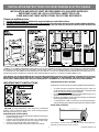
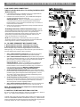
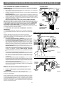
Clearances and Dimensions
1. Provide adequate clearances between the range and adjacent combustible surfaces.
2. Location—Check location where the range will be installed. Check for proper electrical supply, and the stability of the floor.
3. Dimensions that are shown must be used. Given dimensions provide minimum clearance. Contact surface must be solid
and level.
*30" MINIMUM CLEARANCE BETWEEN THE TOP OF THE COOKING SURFACE AND THE BOTTOM OF AN UNPROTECTED WOOD OR METAL
CABINET; OR 24" MINIMUM WHEN BOTTOM OF WOOD OR METAL CABINET IS PROTECTED BY NOT LESS THAN 1/4" FLAME RETARDANT
MILLBOARD COVERED WITH NOT LESS THAN NO. 28 MSG SHEET STEEL, 0.015" STAINLESS STEEL, 0.024" ALUMINUM OR 0.020" COPPER.
0" CLEARANCE IS THE MINIMUM FOR THE REAR OF THE RANGE. FOLLOW ALL DIMENSION REQUIREMENTS PROVIDED ABOVE TO
PREVENT PROPERTY DAMAGE, POTENTIAL FIRE HAZARD, AND INCORRECT COUNTERTOP AND CABINET CUTS.
TO ELIMINATE THE RISK OF BURNS OR FIRE BY REACHING OVER HEATED SURFACE UNITS, CABINET STORAGE SPACE LOCATED
ABOVE THE SURFACE UNITS SHOULD BE AVOIDED. IF CABINET STORAGE IS TO BE PROVIDED, THE RISK CAN BE REDUCED BY
INSTALLING A RANGE HOOD THAT PROJECTS HORIZONTALLY A MINIMUM OF 5" BEYOND THE BOTTOM OF THE CABINETS.
Español - Páginas 5-8
If the information in this manual is not followed
exactly, a fire or electrical shock may result causing property
damage, personal injury or death.
Important Notes to the Installer
• Read all instructions contained in these installation instructions
before installing range.
• Remove all packing material from the oven compartments
before connecting the gas & electrical supply to the range.
• Observe all governing codes and ordinances.
• Be sure to leave these instructions with the consumer.
Fig. 1
Fig. 2
Fig. 3
30"
Important Note to the Consumer
Keep these instructions with your owner's guide for future reference.
• As when using any appliance generating heat, there are
certain safety precautions you should follow. These are listed
in the Use & Care Guide, read it carefully.
• Be sure your range is installed and grounded properly by a
qualified installer or service technician.
• Make sure the wall coverings around the range can withstand
the heat generated by the range.
• To eliminate the need to reach over the surface elements,
cabinet storage space above the elements should be avoided.
IMPORTANT SAFETY INSTRUCTIONS
Serial plate is located on the lower right front frame of the appliance.
Alternate location may be under cooktop.
Serial Plate Locations:
1
INSTALLATION INSTRUCTIONS FOR FREESTANDING ELECTRIC RANGE

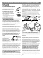
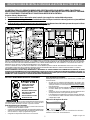
1. ANTI-TIP BRACKET INSTALLATION INSTRUCTIONS
- IMPORTANT SAFETY WARNING
To reduce the risk of tipping of the range, the range must be
secured to the floor by properly installed Anti-Tip Bracket and
screws packed with the range. Failure to install the anti-tip bracket
will allow the range to tip over if excessive weight is placed on an
open door or if a child climbs upon it. Serious injury might result
from spilled hot liquids or from the range itself.
If range is ever moved to a different location, the Anti-Tip Bracket
must also be moved and installed with the range.
Instructions are provided for installation in wood or cement
fastened to either the floor or wall. When installed to the wall,
make sure that screws completely penetrate dry wall and are
secured in wood or metal. When fastening to the floor or wall, be
sure that screws do not penetrate electrical wiring or plumbing.
1a. Locate the Bracket using the Template - (Bracket
may be located on either the left or right side of the range. Use
the information below to locate the bracket if template is not
2a. Models with Factory Connected Power Supply
Cord. NOTE: Some models may have a factory
installed three (3) conductor Power Supply Cord.
2. ELECTRICAL CONNECTION REQUIREMENTS - This
appliance must be properly installed and grounded by a qualified
technician in accordance with the National Electrical Code ANSI/
NFPA No. 70 -- latest edition -- and Local Electrical Code
requirements.
This appliance may be connected by means of "Permanent
Wiring" or "Power Supply Cord Kit."
When installing Permanent Wiring, do not leave excess wire in
range compartment. Excess wire in the range compartment may
not allow the Rear Access Cover to be replaced properly and
could create a potential electrical hazard if wires become pinched.
Connect only as instructed under "Permanent Wire
Connections" in Step 4c. When using flexible conduit or range
cable use flex connector or range cable strain relief (Fig. 11).
Fig. 4
Fig. 5
Fig. 6
Fig. 7
BEFORE STARTING
Tools You Will Need
For leveling legs and Anti-Tip Bracket:
• Adjustable wrench or channel lock pliers
• 5/16" Nutdriver or Flat Head Screwdriver
• Electric Drill & 1/8" Diameter Drill Bit
(Masonry Drill Bit if installing in concrete)
For electrical supply connection:
• 1/4" & 3/8" Socket driver or Nutdriver
Additional Materials You Will Need:
• Power Supply Cord or
• Copper Electrical Wiring & Metal Conduit
(for hard wiring)
NORMAL INSTALLATION STEPS
3/16" pilot hole 1-3/4" deep. The screws provided may be used
in wood or concrete material. Use a 5/16" nut-driver or flat
head screwdriver to secure the bracket in place (See Fig. 6).
1c. Level and Position Range - Level range by adjusting
the (4) leveling legs with a wrench. NOTE: A minimum
clearance of 1/8" is required between the bottom of the range
and the leveling leg to allow room for the bracket. Use a spirit
level to check your adjustments. Slide range back into position
(See Fig. 7).
Visually check that rear leveling leg is inserted into and fully
secured by the Anti-Tip Bracket by removing lower panel or
storage drawer. For models with a Warmer Drawer or broiler
compartment, grasp the top rear edge of the range and carefully
attempt to tilt it forward.
available).
Mark the floor or wall where
left or right side of the range
will be located. If rear of range
is against the wall or no
further than 1-1/4" from wall
when installed, you may use
the wall or floor mount
method. If molding is installed
and does not allow the bracket to fit flush against the wall, remove
molding or mount bracket to the floor. For wall mount, locate the
bracket by placing the back edge of the template against the rear
wall and the side edge of template on the mark made referencing
the side of the range (See Fig. 4). Place bracket on top of
template and mark location of the screw holes in wall. If rear of
range is further than 1-1/4" from the wall when installed, attach
bracket to the floor. For floor mount, locate the bracket by placing
back edge of the template where the rear of the range will be
located. Mark the location of the screw holes, shown in template.
1b. Drill Pilot Holes & Fasten Bracket - Drill a 1/8" pilot
hole where screws are to be located. If bracket is to be mounted
to the wall, drill pilot hole at an approximate 20° downward angle
(See Fig. 5).
If bracket is to be mounted to masonry or ceramic floors, drill a
Mobile home installations, new branch circuit installations
(1996NEC) or areas where Local Codes do not permit grounding
through neutral require a four (4) conductor power supply cord kit
rated at 125/250 volts minimum and marked for use with ranges.
See Range Connection Opening Size Chart (Figs. 9 & 10) for
cord kit ampere rating information. Terminals on end of wires
must be either closed loop or open-end spade lugs with upturned
ends.
2
INSTALLATION INSTRUCTIONS FOR FREESTANDING ELECTRIC RANGE

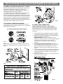
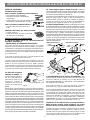
NOTE: Range is shipped from factory with 1-3/8" dia. hole as
shown. To use either 7/8" dia. hole or 1-1/8" dia. knockouts refer
to Fig. 9.
3 & 4 - Wire electrical wall Receptacle types &
Fig. 8
Fig. 9
Rear
Access
Cover
2b. MODELS REQUIRING POWER SUPPLY CORD KIT.
RISK OF FIRE OR ELECTRICAL SHOCK MAY OCCUR IF AN
INCORRECT SIZE RANGE CORD KIT IS USED, THE
INSTALLATION INSTRUCTIONS ARE NOT FOLLOWED OR
STRAIN RELIEF BRACKET IS DISCARDED.
This appliance may be connected by means of a power supply
cord. Only a power supply cord kit rated at 125/250 volts
minimum, and marked for use with ranges shall be used. See Fig.
10 for cord kit ampere rating information. Cord must have either
three (3) or four (4) conductors (See Fig. 8). Terminals on end of
wires must be either closed loop or open-end spade lugs with
upturned ends. Cord must have strain relief properly installed. See
Steps 4a. for 4-Wire or 4b. for 3-Wire connections.
3. ELECTRICAL CONNECTION TO RANGE.
The Rear Access Cover must be removed (Fig 9). To remove,
loosen center screw (one screw) and remove cover. The terminal
block will then be accessible.
Fig. 10
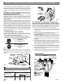
4A. POWER CORD CONNECTIONS
Fig. 11
Fig. 12
(4-Wire Connection Instructions - Refer to Fig.12)
Before wiring the range review the suggested power source
location drawing in Fig. 3. If connecting to a 4-Wire electrical
system (new branch-circuit or mobile home requires 4-Wire
connection):
1. Follow the manufacturer’s installation instructions supplied
with the strain relief and install (Also see Figs. 9, 10 & 11).
2. Insert the end connectors for Line 1, Line 2 and Neutral and
tighten securely to the terminal block.
IMPORTANT NOTE: DO NOT LOOSEN the factory
installed nut connections which secure the range wiring to the
terminal block. Electrical failure or loss of electrical
connection may occur if these 3 nuts are loosened or
removed.
3. You must disconnect the ground strap. Remove the
factory installed ground screw & plate to release the copper
ground strap from the frame of the appliance. Cut and
discard the copper ground strap & plate. KEEP the ground
screw.
4. Connect the ground wire (Green) lead with the eyelet to the
frame of the appliance with the ground screw using the same
hole in the frame where the ground screw was originally
installed (See Fig. 12).
5. Make sure all screws are tightened securely and replace the
rear access cover (See Fig. 9).
3
INSTALLATION INSTRUCTIONS FOR FREESTANDING ELECTRIC RANGE

or 4B. POWER CORD CONNECTIONS
(3-Wire Connection Instructions . For existing installations ONLY
- Refer to Fig. 13).
1. Follow the manufacturer’s installation instructions supplied with the
strain relief and install (Also see Figs. 9, 10 & 11).
2. Insert the end connectors for Line 1, Line 2 and Neutral and tighten
securely to the terminal block (See Fig. 13).
IMPORTANT NOTE: DO NOT LOOSEN the factory installed nut
connections which secure the range wiring to the terminal block.
Electrical failure or loss of electrical connection may occur if these 3
nuts are loosened or removed.
3. Make sure all connections are tightened securely and replace the rear
access cover (See Fig. 9).
Grounding Instructions (3-Wire Connections only): A ground
strap is installed on this range which connects the center terminal of the
terminal block (Neutral) to the range chassis. The ground strap is
connected to the range by the center, lowest screw (See Fig. 13). The
ground strap must not be removed unless National, State or Local
Codes do not permit use of a ground strap.
NOTE: If the ground strap is removed for any reason, a separate
ground wire must be connected to the separate ground screw attached
to the range chassis and to an adequate ground source.
NOTE: Non-terminated field wire compression connections must be
set at approximately 22 in./lbs.
Fig. 13
4c. 3 & 4-WIRE PERMANENT WIRE CONNECTIONS.
3 - Wire Permanent Connection - follow Steps 1,2 & 5 below.
4 - Wire Permanent Connection - follow Steps 1 thru 5 below.
Before wiring the range, review the suggested power source location
drawings in Fig. 3. If connecting to a 4-Wire electrical system (new branch-
circuit or mobile home requires 4-Wire connection):
1. (3 & 4 - Wire Permanent Connections) Follow the manufacturer’s
installation instructions supplied with the strain relief and install.
2. (3 & 4 - Wire Permanent Connections) Strip insulation away from the
ends of the permanent wiring for Line 1, Line 2, Neutral (also strip ground
wire on 4-Wire Connections). Tighten all 3 wire leads to the terminal
block (Follow wire locations shown in Fig. 14).
IMPORTANT NOTE: DO NOT LOOSEN the factory installed nut
connections which secure the range wiring to the terminal block.
Electrical failure or loss of electrical connection may occur if these 3
nuts are loosened or removed. NOTE: For 3-Wire Permanent
Connections skip Steps 3 & 4 and continue with Step 5.
3. (4-Wire Permanent Connection ONLY) Disconnect the ground strap.
Remove the factory installed ground screw & plate to release the factory
installed copper ground strap from frame of the appliance. Cut and
discard the copper strap from the terminal block. KEEP the ground
screw, ground plate and go to Step 4.
4. (4-Wire Permanent Connection ONLY) Connect the ground wire lead
(Green) to the frame of the appliance using the ground screw & plate as
shown in Fig. 15. Be sure to install using the same hole in the frame
where the ground screw was originally installed.
5. (3 & 4 - Wire Permanent Connections) Make sure all connections are
tightened securely and replace the rear access cover (See Fig. 9).
Fig. 14
5. CAREFULLY SLIDE RANGE INTO FINAL LOCATION.
Be sure to provide all the adequate clearances and dimensions shown in
Figs. 1, 2 & 3 before moving appliance into final location.
Carefully slide range into final position while inserting rear leveling leg into
and FULLY ENGAGING THE ANTI-TIP BRACKET (See Fig. 7). Make sure the
power cord folds into the remaining open floor area behind the range Warmer
or storage drawer. Be sure to check the level of the range.
Fig. 15
4
INSTALLATION INSTRUCTIONS FOR FREESTANDING ELECTRIC RANGE

5
LA INSTALACION Y EL SERVICIO DEBEN SER EFECTUADOS POR UN INSTALADOR CALIFICADO.
IMPORTANTE: CONSERVE ESTAS INSTRUCCIONES PARA USO DEL INSPECTOR LOCAL DE ELECTRICIDAD.
LEA Y CONSERVE ESTAS INSTRUCCIONES PARA REFERENCIA FUTURA.
Espacios Libres y Dimensiones
1. Provea espacios libres adecuados entre la estufa y las superficies combustibles adyacentes.
2. Ubicación – Revise el lugar donde será instalada la estufa. Verifique el suministro de energía eléctrica y la estabilidad
del piso.
3.
Es esencial que se usen las dimensiones que se muestran. Las dimensiones indicadas proveen los espacios libres
mínimos. La superficie de contacto debe ser firme y nivelada.
*ESPACIO LIBRE MINIMO DE 30" ENTRE LA CUBIERTA DE COCINAR DE LA ESTUFA Y LA PARTE INFERIOR DE UN ARMARIO DE
METAL O DE MADERA NO PROTEGIDO; O 24" MINIMO CUANDO LA PARTE INFERIOR DE UN ARMARIO DE METAL O DE MADERA
ESTA PROTEGIDA CON CARTON RETARDANTE A LAS LLAMAS DE NO MENOS DE 1/4" CUBIERTO CON CHAPA DE ACERO NO
INFERIOR AL No. 28 MSG, ACERO INOXIDABLE DE 0.015", ALUMINO DE
0.024" O COBRE DE 0.020". EL ESPACIO LIBRE DE 0" ES EL MINIMO PARA LA PARTE TRASERA DE LA ESTUFA. SIGA TODAS
LAS DIMENSIONES INDICADAS ANTERIORMENTE PARA EVITAR DAÑOS MATERIALES, RIESGOS DE INCENDIO Y CORTES
INCORRECTOS DE LOS ARMARIOS Y DE LAS MESADAS.
PARA ELIMINAR EL RIESGO DE QUEMADURAS O INCENDIOS AL PASAR SOBRE LOS ELEMENTOS CALIENTES, SE DEBE
EVITAR COLOCAR ARMARIOS DE ALMACENAMIENTO SOBRE LA ESTUFA. SI SE INSTALAN ARMARIOS SOBRE LA ESTUFA, SE
PUEDEN REDUCIR TALES RIESGOS INSTALANDO UNA CAMPANA EXTRACTORA QUE SE PROYECTE HORIZONTALMENTE UN
MINIMO DE 5" MAS AFUERA DE LA PARTE INFERIOR DE LOS ARMARIOS.
English - Pages 1-4
· TODAS LAS ESTUFAS
PUEDEN VOLCARSE.
· SE PUEDEN CAUSAR
LESIONES.
· INSTALE EL DISPOSITIVO
ANTIVUELCO INCLUIDO
CON LA ESTUFA.
· VEA LAS INSTRUCCIONES
DE INSTALACION.
Fig. 1 Fig. 2
Fig. 3
Si no se sigue estrictamente la información de
este manual, se puede producir un incendio o un choque eléctrico
que cause daños materiales, lesiones corporales o fatales.
Notas Importantes para el Instalador
• Lea todas las instrucciones indicadas en estas instrucciones de
instalación antes de instalar la estufa.
• Saque todo el material de empaque del compartimiento del horno
antes de conectar el suministro de gas y de electricidad a la estufa.
• Observe todos los códigos y reglamentos vigentes.
• Asegúrese de dejar estas instrucciones con el usuario.
30"
Ubicación de la placa de serie:
Ubicación de la placa de serie:
La placa de serie está ubicada en el costado derecho del marco
delantero inferior del electrodoméstico.
INSTRUCCIONES IMPORTANTES DE SEGURIDAD
Aviso importante al consumidor
Mantenga estas instrucciones con su Guía de Uso y Cuidado para
referencia futura.
• Al igual que con cualquier electrodoméstico que genere calor,
existen ciertas precauciones de seguridad que usted debe seguir.
Tales precauciones se encuentran en la
Guía de Uso y Cuidado,
léala atentamente.
• Asegúrese de que la estufa esté bien instalada y sea puesta a tierra
en forma debida por un instalador calificado o un técnico de
servicio.
• Asegúrese de que el revestimiento de la pared alrededor de la
estufa pueda resistir el calor generado por la estufa.
• Para eliminar la necesidad de tener que pasar sobre los elementos,
se recomienda no instalar armarios arriba los elementos de la
cubierta de la estufa.
INSTRUCCIONES DE INSTALACION PARA LA ESTUFA ELECTRICA DE 30"
Page is loading ...
Page is loading ...
Page is loading ...

station
Page is loading ...
-
 1
1
-
 2
2
-
 3
3
-
 4
4
-
 5
5
-
 6
6
-
 7
7
-
 8
8
-
 9
9
-
 10
10
-
 11
11
-
 12
12


