Page is loading ...

COPYRIGHT © OCTOBER, 2012 BY GRIZZLY INDUSTRIAL, INC. REVISED OCTOBER, 2013 (BL)
WARNING: NO PORTION OF THIS MANUAL MAY BE REPRODUCED IN ANY SHAPE
OR FORM WITHOUT THE WRITTEN APPROVAL OF GRIZZLY INDUSTRIAL, INC.
#JM15437 PRINTED IN USA
The Model T25414 is the same kit as the Model H8070, except it features an alder body without the curly
maple veneered top. Except for the differences noted in this insert, all other content in the Model H8070
owner's manual applies to this kit. Before working with your new kit, you MUST read and understand this
insert and the entire Model H8070 manual.
If you have any further questions about this manual insert or the differences between the Model T25414 and
the Model H8070, contact our Technical Support at (570) 546-9663 or email [email protected].
MODEL T25414
HEIRLOOM
COUNTRY/BLUEGRASS
ALDER GUITAR KIT
MANUAL INSERT
V1.10.13

-2-
T25414 Manual Insert
T25414 Parts Inventory
Figure 2. Guitar parts.
6
3
4
7
8
5
13
Figure 1. Boxed components.
1
2
REF PART # DESCRIPTION
1 PT25414001 ALDER GUITAR BODY
2 PH8070002 NECK
3 PH8070003 PICK GUARD
4 PH8070004 NECKPLATE
5 PH8070005 TUNING MACHINE 6-PC
6 PH8070006 CONTROL PLATE
7 PH8070007 BRIDGE
8 PH8070008 PICKUP
9 PH8070009 HEX NUT BUSHING
10 PH8070010 OUTPUT JACK COVER
11 PH8070011 OUTPUT JACK
12 PH8070012 STRING SET 6-PC
13 PH8070013 STRAP BUTTON
14 PH8070014 CHROME SCREW 5 X 45MM
15 PH8069018 CHROME SCREW 3.5 X 25MM
16 PH8069019 CHROME SCREW 3.1 X 12MM
17 PH8070017 CHROME SCREW 2.1 X 14MM
18 PH8070018 CHROME SCREW 2.5 X 16MM
19 PH8069021 CHROME SCREW 2.5 X 14MM
20 PH8070020 ROUND STRING RETAINER
21 PH8070021 STRING NUT
22 PH8070022 FERRULE
23 PAW04M HEX WRENCH 4MM
24 PAW01.5M HEX WRENCH 1.5MM
25 PW01M FLAT WASHER 8MM
Inventory
Figure 3. More guitar parts.
10
18
21
11
12
16
15
14
22
23
19
20
24
9
17
13
25

COPYRIGHT © NOVEMBER, 2006 BY GRIZZLY INDUSTRIAL, INC. REVISED OCTOBER, 2013 (BL)
WARNING: NO PORTION OF THIS MANUAL MAY BE REPRODUCED IN ANY SHAPE
OR FORM WITHOUT THE WRITTEN APPROVAL OF GRIZZLY INDUSTRIAL, INC.
#BL8552 PRINTED IN KOREA
MODEL H8070
HEIRLOOM CLASSIC-STYLE
GUITAR KIT
OWNER'S MANUAL
(For models manufactured since 7/06)
V1.10.13

For Your Own Safety,
Read Instruction Manual
The purpose of safety symbols is to attract your attention to possible hazardous conditions.
This manual uses a series of symbols and signal words intended to convey the level of impor-
tance of the safety messages. The progression of symbols is described below. Remember that
safety messages by themselves do not eliminate danger and are not a substitute for proper
accident prevention measures.
Indicates a potentially hazardous situation which, if not avoided,
MAY result in minor or moderate injury. It may also be used to alert
against unsafe practices.
Indicates a potentially hazardous situation which, if not avoided,
COULD result in death or serious injury.
Indicates an imminently hazardous situation which, if not avoided,
WILL result in death or serious injury.
This symbol is used to alert the user to useful information about
proper operation of the machine.
NOTICE
Some dust created by power sanding, sawing, grinding, drilling, and other construction activi-
ties contains chemicals known to the State of California to cause cancer, birth defects or other
reproductive harm. Some examples of these chemicals are:
Your risk from these exposures varies, depending on how often you do this type of work.
To reduces your exposure to these chemicals: Work in well ventilated area, and work with
approved safety equipment, such as those dust masks that are specifically designed to filter
out microscopic particles.
• Lead from lead-based paints.
• Crystalline silica from bricks, cement, and other masonry products.
• Arsenic and chromium from chemically-treated lumber.

Table of Contents
SECTION 1: SAFETY ....................................................................................................................... 2
SECTION 2: INTRODUCTION.......................................................................................................... 3
Foreword .................................................................................................................................... 3
Contact Info ................................................................................................................................ 3
SECTION 3: PARTS INVENTORY ................................................................................................... 4
Inventory ..................................................................................................................................... 4
Supplies/Tools ............................................................................................................................ 5
Identification ............................................................................................................................... 6
SECTION 4: ASSEMBLY ................................................................................................................. 7
Shaping Headstock .................................................................................................................... 7
Sanding Body ............................................................................................................................. 8
Sanding Neck ............................................................................................................................. 8
Finishing Neck ............................................................................................................................ 9
Finishing Body ............................................................................................................................ 9
Mounting Neck ......................................................................................................................... 10
Positioning Pick Guard, Control Plate & Bridge ....................................................................... 12
Installing Ferrules ..................................................................................................................... 13
Mounting Tuners ...................................................................................................................... 14
Wiring Pickups.......................................................................................................................... 15
Installing Output Jack ............................................................................................................... 16
Installing Bridge, Pickups & Controls ....................................................................................... 16
Strap Buttons............................................................................................................................ 17
Installing Nut............................................................................................................................. 17
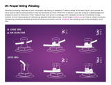
Winding Strings ........................................................................................................................ 18
String Retainers........................................................................................................................ 19
SECTION 5: SETUP ....................................................................................................................... 20
General ..................................................................................................................................... 20
Neck Adjustment ...................................................................................................................... 20
String Height............................................................................................................................. 21
Pickup Height ........................................................................................................................... 22
Tuning ...................................................................................................................................... 22
Setting Intonation ..................................................................................................................... 23
SECTION 6: REFERENCE INFO ................................................................................................... 24
Accessories .............................................................................................................................. 24
Electrical Components ............................................................................................................. 27
Wiring Diagram......................................................................................................................... 29
WARRANTY AND RETURNS ........................................................................................................ 30

SECTION 1: SAFETY
These instructions assume that you are intimately familiar with the safe operation and use of
woodworking machinery and woodworking tools, and understand the techniques used to build this
project. If you do not qualify for both of these criteria, STOP building this project for your own
safety. Read and understand the owners manual for the machinery you intend to use, take a wood-
working class or visit your local library for more information. Woodworking machinery and tools
are inherently dangerous because they use sharp edges that can and will cause serious personal
injury including amputation and death. Do not underestimate the ability of these tools and machin-
ery to cause injury. Never operate any tool without all guards in place and always wear approved
safety glasses. For your own safety, please heed this warning.
Always wear safety glasses or goggles when operating equipment. Everyday glasses or read-
ing glasses are not safety glasses. Be certain the safety glasses you wear meet the appropri-
ate standards of the American National Standards Institute (ANSI).
Because there are various ways to cut and join wood, you can make substitutions for the methods
stated in this plan. We try to suggest the easiest methods possible. However, only you know your
skills with each piece of machinery. Never compromise your safety by using a cutting method
with which you are not comfortable. Instead, find an alternative approach that will yield the same
result.

Model H8070 (Mfg. Since 7/06)
-3-
Foreword
SECTION 2: INTRODUCTION
We are proud to offer the Model H8070 Heirloom
Classic-Style Guitar Kit. This kit is a part of a
growing Grizzly family of fine woodworking prod-
ucts. When assembled according to the guide-
lines set forth in this manual, you can expect
years of enjoyment from your guitar.
We are pleased to provide this manual for the
Model H8070. It was written to guide you through
assembly, review safety considerations, and cover
general information. It represents our effort to pro-
duce the best documentation possible.
Most importantly, we stand behind our products. If
you have any questions or parts requests, please
call or write us at the location listed below.
Grizzly Industrial, Inc.
1203 Lycoming Mall Circle
Muncy, PA 17756
Phone: (570) 546-9663
Fax: (800) 438-5901
E-Mail: techsupport@grizzly.com
Web Site: http://www.grizzly.com
The specifications, drawings, and photographs
illustrated in this manual represent the Model
H8070 as supplied when the manual was pre-
pared. However, owing to Grizzly’s policy of con-
tinuous improvement, changes may be made at
any time with no obligation on the part of Grizzly.
For your convenience, we always keep current
Grizzly manuals available on our website at
www.grizzly.com.
Contact Info

-4-
Model H8070 (Mfg. Since 7/06)
SECTION 3: PARTS INVENTORY
Figure 1. Boxed components.
Inventory
1
REF PART# DESCRIPTION QTY
1 PH8070001 Guitar Body 1
2 PH8070002 Neck 1
3 PH8070003 Pick Guard 1
4 PH8070004 Neckplate 1
5 PH8070005 Tuning Machine 6
6 PH8070006 Control Plate 1
7 PH8070007 Bridge 1
8 PH8070008 Pickup 1
9 PH8070009 Hex Nut Bushing 6
10 PH8070010 Output Jack Cover 1
11 PH8070011 Output Jack 1
12 PH8070012 String 6
13 PH8070013 Strap Button 2
14 PH8070014 Chrome Screw 5 x 45mm 4
15 PH8070015 Chrome Screw 3.5 x 25mm 8
16 PH8070016 Chrome Screw 3.1 x 12mm 12
17 PH8070017 Chrome Screw 2.1 x 14mm 6
18 PH8070018 Chrome Screw 2.5 x 16mm 2
19 PH8070019 Chrome Screw 2.5 x 14mm 2
20 PH8070020 Round String Retainer 2
21 PH8070021 String Nut 1
22 PH8070022 Ferrule 6
23 PAW04M Hex Wrench 4mm 1
24 PAW01.5M Hex Wrench 1.5mm 1
25 PW01M Flat Washer 8mm 6
2
Figure 2. Guitar parts.
6
3
4
7
8
5
Figure 3. More guitar parts.
10
18
21
11
12
13
16
15
14
22
23
19
20
24
9
17
25

Model H8070 (Mfg. Since 7/06)
-5-
Most wood components in this kit are fully
machined at the factory and are ready for assem-
bly. A small amount of sanding and finishing is
needed to complete your guitar.
Recommended Tools & Supplies:
• Sharp Pencil
• Drill Press
•
Drill Bits:
1
⁄
16
",
3
⁄
32
",
5
⁄
32
",
5
⁄
16
",
11
⁄
32
",
25
⁄
64
"
• Electric/Cordless Drill
• Depth Stop
• NIOSH Approved Respirator
• ANSI Approved Safety Glasses
• Aluminum-Oxide Sanding Paper #150, #220
and #320 Grit
• Wet and Dry Sanding Paper #400, #600, and
#1000 Grit
• Flexible Sanding Block
• Wood Glue
• Chisel or Razor Blade
• Phillips Screwdriver #1, #2
•
1
⁄
4
" Steel Rod or a Coat Hanger
• Masking Tape
• Tack Cloth
Supplies/Tools
• Bandsaw with
1
/
4
" Blade or Coping Saw
• Tack Cloth or Soft Cloth
• Sanding Sealer
• Assorted Wood Files
• Buffing Compounds
• Oil Wood Finish
• Soldering Iron and Solder
• Peghead Reamer or a Round File
• Rubber Dead Blow Hammer
• Tweezers, Pliers, Wire Cutters
• C-Clamps
• Temporary Wood Handle:
Approximately 1" x 2" x 16"
• Guitar Capo
• Feeler Gauge Set
• Spray Primer and Finish (See Note Below)
• 18" Metal Straightedge (
1
⁄
32
" Resolution)
• 36" Metal Straightedge
•
Steel Ruler (
1
⁄64" Resolution)
• Wood Dowel
• Wood Blocks: 4" x 4" x 12" (2)
•
Wood Shim:
7
⁄16" Thick
Note: Use the same type of paint for primer
and finish—either enamel or lacquer base.
Do not use different base paints for priming
or finishing or your results may not be desir-
able.

-6-
Model H8070 (Mfg. Since 7/06)
Identification
Headstock
Neck
Strap
Button
Bridge
Fret
Tuning Post
Figure 4. Model H8070 controls.
Figure 5. Model H8070 headstock features.
Volume
Knob
Tone
Knob
Output
Jack
Pickups
Strap
Button
Three-Way
Switch
String Retainers
Nut
String Slot
Neck Pocket
Tuner or Tuning Machine

Model H8070 (Mfg. Since 7/06)
-7-
SECTION 4: ASSEMBLY
The headstock for these models comes unfin-
ished so you can cut it to your own design. These
instructions will guide you through designing the
shape of the headstock and placing pegholes.
Components Needed Qty
Guitar Neck ....................................................... 1
Tools Needed
Sharp Pencil ......................................................1
Paper ......................................................Varioius
Bandsaw with a
1
⁄4" Blade or a Coping Saw .....1
Woodworking Files ................................ Assorted
Drill Press with
5
⁄16" and
25
⁄64" Drill Bits ................1
To shape the headstock:
1. Trace the headstock on a piece of paper. Test
various ideas for headstock shapes on paper
before cutting into the headstock.
2. Layout pegholes for the tuners. Space the
centers of the pegholes exactly
15
⁄16" apart,
and a minimum of
1
⁄2" from the edge of the
headstock, as shown in Figure 6.
Shaping Headstock
Note: To determine the string slot (Figure 5)
locations, you can place the nut on the draw-
ing and mark the slots. If the strings cross the
nut at a sharp angle, this increases friction
and makes tuning difficult. It also increases
the risk of the strings pulling out of the nut
slots.
4. Layout the tuners on the test paper to ensure
they are stacked tightly against each other.
(See Page 14 for instructions on installing the
tuners.)
5. Redraw your final headstock shape onto the
headstock with a pencil.
6. Cut the headstock out with a bandsaw or
coping saw. Be sure to cut only to the outside
edge of your pencil line.
Note: To cut sharp corners, cut several slots
perpendicular to the corner, then cut out the
small pieces. This will reduce binding on the
blade.
7. Carefully hand file the headstock to finalize
the shape.
8. Mark the pegholes onto the headstock.
15
⁄
16
"
15
⁄
16
"
15
⁄
16
"
15
⁄
16
"
15
⁄
16
"
1
⁄
2
"
Figure 6. String paths and peghole locations.
Figure 7. Drilling the pegholes.
9. Using a
5
⁄16" bit, drill holes through the head-
stock from the top for the tuner shafts, as
shown in Figure 7.
3. Draw the path of the strings onto the test
paper to ensure that the strings do not inter-
fere with each other.

-8-
Model H8070 (Mfg. Since 7/06)
Like the guitar body, the guitar neck has been
rough sanded at the factory. Final sanding should
be done as described in the previous sub-section
Sanding Body. Consider applying inlays or addi-
tional design work on the fretboard and head-
stock before final sanding.
Note: If you are considering inlays or other design
work, take time to test your designs in scrap wood
before performing the work on the instrument.
The fretboard requires no sanding. Sanding the
fretboard will affect the playability of the guitar
and could lead to irrepairable damage.
Sanding Neck
The guitar body has been sanded at the factory,
but it is up to you to do the final sanding before
the finish is applied. To get a good finish, the
body should be sanded with a series of sandpa-
per grits up to #320 grit.
Components and Hardware Needed: Qty
Guitar Body ....................................................... 1
To sand the guitar body:
1. Wear a NIOSH-approved respirator and
ANSI-approved safety glasses when
sanding wood!
2. Use a flexible sanding block with #150 grit
aluminum-oxide sanding paper to sand the
guitar body until there is a consistent scratch
pattern on the entire surface.
Note: DO NOT round over the neck pocket
or the body cavities.
When hand sanding, always sand in the
same direction as the wood grain.
3. Resand the entire guitar body with #220 grit
sanding paper and lightly round over the out-
side edges of the body.
Sanding Body
4. Wipe the guitar body with a damp cloth to
“raise” the wood grain.
5. Wait until the wood is dry and resand the
entire body with #220 grit sandpaper to sand
the “raised” grain smooth.
6. Repeat Step 4 & 5.
Note: If you want to stain your guitar, the stain
should be applied now before continuing with
the next step. Stains cannot be applied to
the guitar body after the sanding sealer is
applied.
7. Apply a primer if you plan to paint the guitar
a solid color. Apply a coat of sanding sealer
if you stained the guitar. Use the sealer
or primer according to the manufacturer's
instructions.
Note: Make sure the primer or sealer you use
is compatible with your finish.
8. When the sanding sealer or primer is dry, use
#320 grit sandpaper for final sanding. DO
NOT sand through to bare wood.
10. Turn the neck over and fasten a
9
⁄16" thick
wood shim with tape to the top side of the
headstock and over the tuner holes. This will
help stabilize the neck during the next step.
11. Center a
25
/64" bit over each hole drilled in
Step 7, and drill down
11
/32" for the base of the
tuners.
12. Place the tuners into the holes on the back
of the headstock to check their position. The
ends of the tuners should touch each other.
—If the tuners overlap, carefully widen the
shaft of the overlapping tuner and adjust
its position relative to each of the other
tuners.

Model H8070 (Mfg. Since 7/06)
-9-
5. Apply the finish according to Finishing Body,
Steps 5–10, on Page 10.
6. Before wet sanding, remove the masking
tape from the fretboard and carefully scrape
any excess finish off the fretboard with a
razor blade or chisel held perpendicular to
the surface, as shown in Figure 8.
Figure 8. Scraping the fretboard.
7. Let wood dry naturally and completely.
8. Use a clean rag to wipe wood finishing oil on
the dryed surface of the fretboard.
Some of the finishing options include stains, lac-
quers, varnishes and oil finishes. Traditionally,
this style of guitar has a clear finish on the neck.
Depending on the type, finishes can be applied
with a spray gun, brush, rag, or a spray can.
Finish materials and books on finishing instru-
ments can be ordered through Grizzly Industrial
or numerous luthier supply catalogs.
Components and Hardware Needed: Qty
Guitar Neck ....................................................... 1
To finish the guitar neck:
1. Mask off the surface of the fretboard. Carefully
press all the masking tape edges securely to
the fretboard. The finish coat can seep under
these edges, especially near corners, uneven
edges, and places where the frets meet the
fingerboard.
2. Make an "S" shaped hook out of
1
/4" steel
rod or a coat hanger that has been folded in
half.
3. Wipe the entire neck with a tack cloth to
remove any dust.
4. Thread the hook through the upper peghole
and hang the neck in the finishing room.
Finishing Neck
Most finishes are hazard-
ous to your health. Wear a
NIOSH/OSHA approved res-
pirator with particulate and
gas/vapor filters, safety
glasses, rubber gloves, and
work in a well ventilated area
when finishing.
This guitar looks incredible with a clear finish that
highlights the wood grain patterns. The surface
can be stained prior to finishing or a transparent
pigment can be added to the finish. These instruc-
tions guide you through a very basic finishing pro-
cess. Books describing different guitar finishing
techniques are available through luthier supply
catalogs, or through your local library. Clear finish
materials and books on finishing can be ordered
through Grizzly Industrial. Finishing a guitar is a
difficult task. If you are unsure of your skills; do
your research, practice on scrap wood, or take it
to a professional.
Components and Hardware Needed: Qty
Guitar Body ....................................................... 1
To finish the guitar body:
1. Mask off the neck pocket (Figure 4). Press
the masking tape tight against the edges of
the pocket so the finish does not seep under
the tape.
2. Screw through the neck pocket screw holes
into a long piece of wood to use for a handle
during spraying. Drill a hole in the end of the
handle for hanging from a hook.
3. Wipe the entire guitar body with a tack cloth
to remove all dust.
4. Thread the hook through the temporary han-
dle and hang the body in the finish room.
Finishing Body

-10-
Model H8070 (Mfg. Since 7/06)
NOTICE
Dust particles suspended in the air will
settle on wet finishes, causing less than sat-
isfactory results. To avoid this problem:
• Leave the finishing room undisturbed
for 24 hours prior to applying the fin-
ish.
• Avoid making unnecessary movements
when entering the finish room.
• Apply the finish to the desired guitar
parts and immediately leave the finish
room.
• DO NOT return to the room until the
specified drying time has elapsed.
Mounting Neck
Figure 9. Making neck and body flush.
Components and Hardware Needed: Qty
Guitar Body ....................................................... 1
Neck .................................................................. 1
Silver Neckplate................................................. 1
Chrome Screws 5 x 45mm ................................ 4
Unless otherwise indicated, we strongly recom-
mend using a drill press for the majority of drilling
to obtain the most precise results. However, an
electric/cordless drill fitted with a depth stop or a
drill stand can be used if you do not have a drill
press.
We recommend using a hollow punch (see Page
24, Accessories) to carve out holes in the finish
before drilling any holes. Also, a router pad can
help reduce scratches in the finish.
To mount the neck to the guitar body:
1. Insert the neck into the neck pocket, and
check to make sure the neck and body are
flush as shown in Figure 9.
2. Clamp the neck and body together.
3. Set the guitar facedown on top of two 4x4's
(cut to 12") for support.
5. Apply several thin coats of the finish, follow-
ing the manufacturer's instructions. Multiple
thin coats usually produce a better quality
finish than one heavy coat.
6. Sand the entire body with #400 grit wet and
dry sandpaper after at least three coats of fin-
ish have been applied. DO NOT sand through
the finish—be careful on the edges.
7. Apply more finish, sanding between coats,
until the finish is the desired thickness.
Note: If finishing with a solid color, you may
wish to apply several coats of a clear finish
over the top, sanding between coats, to add
depth to the finish.
8. When the final coat has dried at least a week,
preferably a month, remove the temporary
handle and masking.
9. Wet sand the finish using #600 grit wet and
dry sandpaper using a sanding block, fol-
lowed with #1000 grit wet and dry sandpa-
per.
10. Buff the finish by hand or with a buffer, start-
ing with a medium polish and work up to a
high gloss polish.
Note: If using a buffing machine, be careful
to avoid going through the finish, especially
on the edges.

Model H8070 (Mfg. Since 7/06)
-11-
Figure 10. Making a pilot hole in the neck.
5. Unclamp the neck from the body.
To determine neck mounting hole depth:
1. Secure the
5
⁄32" drill bit in the drill press chuck,
raise the table, and set the neck, fretboard-
down, on top of a clean piece of scrap wood
on the table.
2. Set the drill press depth stop so the tip of
the bit will ONLY drive half way through the
neck.
Note: Correctly set the depth stop or the bit
may drill through the fretboard!
Another way to determine neck mounting hole
depth (Optional):
1. Insert the neck into the neck pocket.
2. Place the neckplate on top of the body so a
mounting hole protrudes beyond the body
and neck (see Figure 11).
3. Insert a 5 x 45mm screw through the plate
so it hangs down to the side of the neck and
body.
4. Gently mark the screw tip depth with a pen-
cil.
Note: You may want to cover the screw tip
marking location with masking tape to avoid
scratching the finish.
4. Insert a
5
⁄32" drill bit into each neck hole
(Figure 10). While pressing down slightly,
twist the drill bit by hand to make pilot holes n
the neck.
Figure 11. Using screw tip depth to set depth
stop.
5. Set the neck fretboard face down on the drill
press table, and set the depth stop to the
mark from Step 4.
To drill mounting holes in the neck:
1. Lower the
5
⁄32" drill bit over the center of the
pilot holes and drill the holes to the correct
depth.
To mount the neck to the body:
1. Insert the neck into the neck pocket, and
place the neckplate on the body.
Note: Do not glue the neck to the body.
2. Align the mounting holes in the neck and
body and neckplate.
3. Fasten the four 5 x 45mm screws, but do not
final tighten them (Figure 12).
Figure 12. Fastening neck to body.

-12-
Model H8070 (Mfg. Since 7/06)
Figure 13. Control plate fits into pick guard.
Positioning Pick
Guard, Control Plate
& Bridge
The following steps require you to mark the guitar
body. To avoid damaging the finish, place mask-
ing tape on the guitar body and gently mark the
tape.
In the following steps the bridge, control plate, and
pick guard will be installed temporarily to correctly
orient them.
Components and Hardware Needed: Qty
Guitar Body and Neck (Assembled) .................. 1
Pick Guard ......................................................... 1
Control Plate ....................................................... 1
Bridge ................................................................ 1
To position the pick guard, control plate and
bridge:
1. Turn the guitar face up, thread the pick
guard pickup wires through the center cavity
(Figure 13) into the control plate cavity, then
place the pick guard on the body.
2. Tuck the control plate wires into the control
plate cavity.
3. Place the control plate on the body so it fits
snugly into the curve on the pick guard as
shown in Figure 13.
4. Place a 36" long straightedge over the center
of the fretboard inlays and over the bridge
cavity, then mark the center line on the guitar
body (Figure 14).
5. Place a ruler across the body at several loca-
tions and mark the half-way point to double
check the center line location against the
mark in Step 5.
Figure 14. Marking center line.
Figure 15. Measuring 25
1
/2" from nut along
center line.
Nut
Slot
6. Insert the bridge into the bridge cavity and
align the mounting holes.
7. Using the straightedge, measure 25
1
⁄2" from
the fretboard side of the nut slot (Figure
15) along the center line to the bridge point
(Figure 16), and mark this location on the
guitar.
Center Cavity
Control Plate Cavity

Model H8070 (Mfg. Since 7/06)
-13-
8. Using a Phillips head screwdriver, turn the
lower saddle adjustment screw so the set
screws shown in Figure 16 are centered over
the bridge point.
Figure 16. Bridge point and high E saddle
adjustment screw.
Bridge Point
Set
Screws
Lower Saddle
Adjustment Screw
Note: Take care to correctly position the con-
trol plate mounting holes so you do not drill
into the control plate cavity.
Figure 17. Marking control plate holes.
9. Align the control plate, pick guard, and
bridge so the bridge is parallel to the control
plate (leave an even distance between the
pickguard and bridge).
10. Mark the mounting holes for the control plate
and pick guard (Figure 17), then remove
these components, as well as the neck,
bridge, and pick guard pickup.
11. Using a
1
⁄16" drill bit, drill
3
⁄8" deep holes in the
body for the pick guard and control plate.
12. Determine whether you want to mount the
strings through the bridge or whether you
want to mount them to the body using the
ferrules.
— If you decide to mount the strings through
the bridge, skip to Mounting Tuners,
Page 14.
—If you decide to mount the strings through
the body, go to Installing Ferrules.
Installing Ferrules
The strings can be installed through the body
using the ferrules—instead of just through the
bridge. One advantage of using the ferrules is that
the strings will sustain notes longer. Ferrules can
be mounted flush (Figure 18) or above (Figure
19) the surface of the guitar.
Figure 18. Flush mounted ferrules.
Figure 19. Above surface mounted ferrules.
Components and Hardware Needed: Qty
Guitar Body ....................................................... 1
Ferrules ............................................................. 6

-14-
Model H8070 (Mfg. Since 7/06)
To install the ferrules:
1. Determine whether you want to flush mount
the ferrules or let them sit above the body.
For flush mounting instructions, go to Flush
Mounting on this page. To mount ferrules
above the guitar body, go to Above Surface
Mounting on this page.
Flush Mounting
1. Place the body topside down on a drill press
and drill
7
⁄16" down into a predrilled pilot hole
using a a
1
⁄4" bit.
2. Using a
5
⁄16" drill bit, drill
3
⁄64" deep into the
same pilot hole.
Note: We recommend setting the depth stop
and using a
5
/16" end mill for greater preci-
sion.
3. Repeat Steps 1-2 for each of the other ferrule
holes.
4. Set the ferrules into the holes so they are
flush with the surface of the guitar.
Above Surface Mounting
1. Place the top of the guitar face down on a
drill press table, then drill
3
⁄8" down into the
predrilled pilot holes using a
1
⁄4" bit.
2. Note: We recommend using a depth stop for
greater precision.
3. Drive the ferrules into the holes with a rubber
dead blow hammer.
4. Go to Mounting Tuners.
Components and Hardware Needed: Qty
Neck .................................................................. 1
Tuners ................................................................ 1
Flat Washers 8mm ............................................ 6
Hex Nut Bushings .............................................. 6
Chrome Screws 2.1 x 14mm ............................. 6
Mounting Tuners
To install the tuners:
1. Place the six tuners into the holes on the back
of the headstock. The holes may need to be
widened with a peghead reamer or a round
file. DO NOT widen the holes too much—the
tuners should fit snugly.
2. Slide a washer over the tuner post and screw
the hex nut bushing onto the tuner, as shown
in Figure 20.
Figure 20. Installing hex nut bushing onto tuner.
Tuner Post
Washer
Hex Nut
Bushing
3. Align the tuners perpendicular to the edge of
the headstock and parallel to each other, as
shown in Figure 21. Use a strip of masking
tape to secure their position on the head-
stock.
Figure 21. Tuners aligned to edge of headstock.
Tuner
Mounting Hole

Model H8070 (Mfg. Since 7/06)
-15-
Wiring Pickups
This guitar comes with a control plate that has
most of the components soldered in place. You
only need to solder the pickup wires onto the three
way switch and volume control. If done incorrectly,
the soldering can damage the components. If you
are unsure of your skills, do your research, prac-
tice on scrap wires, or take it to a professional.
Components and Hardware Needed: Qty
Guitar Body ....................................................... 1
Control Plate ...................................................... 1
Pick Guard ......................................................... 1
Pick Guard Pick Up ........................................... 1
Bridge ............................................................... 1
Output Jack ....................................................... 1
To wire the pickups:
1. Thread the pick guard pickup and bridge
pickup wires through the channels and holes
in the control plate cavity as shown in Figure
22. (Also, refer to the Wiring Diagram on
Page 29 and the Electrical Photos on
Pages 27-28.)
Figure 22. Wires threaded through body.
Audio Jack Wire
Ground
Wire
Pick Guard
Pickup
Wires
Bridge
Wires
Control
Plate
Cavity
Bridge
Cavity
2. Thread the ground wire through the hole in
the control plate cavity and into the bridge
cavity (Figure 22).
3. Push the audio jack wire out through the hole
in the end of the body.
4. Using a
1
⁄16" drill bit in a drill press, drill
3
⁄8"
deep holes into the back of the headstock
through each tuner mounting hole.
Note: Drilling the holes deeper than
3
⁄8" could
result in drilling out through the front face
of the headstock. Use a depth stop or tape
wrapped around the drill bit at the correct
depth as an indicator.
5. Secure the tuners to the guitar headstock
with the 2.1 x 14mm screws.
4. Solder the pickup wires to the volume and
three way switch as shown in the Wiring
Diagram on Page 29 and the Electrical
Photos on Pages 27-28.
5.
Solder the audio jack wires onto the output
jack.

-16-
Model H8070 (Mfg. Since 7/06)
Installing Output
Jack
Components and Hardware Needed: Qty
Output Jack ....................................................... 1
Output Jack Cover ............................................. 1
Chrome Screws 3.1 x 12mm
.............................. 2
To install the output jack:
1. Thread the output jack onto the jack cover.
2. Place the output jack cover in the jack cavity,
and mark the mounting holes.
3. Using a
1
/16" drill bit, drill
3
/8" holes at a 45º
angle into the body as shown in Figure 23.
Figure 23. Drilling output jack mounting holes.
4. Mount the output jack cover with two
3.1 x
12mm screws.
Installing Bridge,
Pickups & Controls
Figure 24. Ground wire above bridge cavity.
3. Secure the bridge with the 3.5 x 25mm
screws, and fasten the control plate with 3.1
x 12mm screws.
To reduce humming in your amp, the ground wire
must contact the bridge plate.
Components and Hardware Needed: Qty
Guitar Body ....................................................... 1
Pick Guard ......................................................... 1
Chrome Screws 3.5 x 25mm ............................. 4
Chrome Screws 3.1 x 12mm .......................... 10
To install the control plate and pickups:
1. Tape the ground wire so the exposed por-
tion curls over the bridge cavity as shown in
Figure 24.
2. Place the bridge into the cavity so the plate
makes contact with the wire.
Ground Wire
/