Page is loading ...

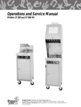
Operations and Service Manual
FOODSERVICE EQUIPMENT
Giles Enterprises, Inc.
P.O. Box 210247 • 2750 Gunter Park Drive West • Montgomery, AL 36121-0247 USA
(334) 272-1457 • Service Hotline 1-800-554-4537 (USA & Canada Only) • FAX (334) 272-3561 • www.gilesent.com
Form No. 64897 (6/98)
Models WOG-D
and WOG-VH-D

Safety Precautions
FOR YOUR SAFETY
DO NOT store or use gasoline or other flammable vapors and liquids in the vicinity of this
or any other appliance!
Warning!!
Improper installatiion, adjustment, alteration, service or maintenance can cause property
damage, injury or death. Read the installation, operating, and maintenance instructions
thoroughly before installing or servicing this equipment.
POST IN A PROMINENT LOCATION
!
!

Table of Contents
I Introduction 2
1 Installation
1 - 1 Installation Instructions 3
1 - 2 Removal of Fryer From Crate 5
1 - 3 Ventilation of Fryer 5
1 - 4 Electrical Requirements 5
2 Operating Instructions 6
3 Fryer Components and Their Functions 8
3 - 1 Control Panel 9
3 - 2 Lower Cabinet Area 10
3 - 3 Cooking Vessel 12
3 - 4 Air Cleaning Components 15
4 Testing the Fryer 16
4 - 1 Proper Control Settings for Check-Out 16
4 - 2 Operational Check of Heating Elements 16
4 - 3 Operational Check-Out of WOG-VH-D Filter Pan Heating System 18
4 - 3 Operational Check-Out of the Filter Pump 18
5 Preparing the Fryer for Operation 19
5 - 1 Fryer Boil-Out Procedure 19
5 - 2 Cleaning of Filter Pan / Replacement of Filter Pan 24
5 - 3 Cleaning Considerations for the Giles Ventless Hood Fryers 26
5 - 4 Removal and Replacement of Filters 27
5 - 5 Operating Fryer’s Controls for Cooking 29
5 - 6 Filtering the Fryer 30
5 - 7 Inspection and Testing of Safety Interlocks 32
6 Fire Suppression System 34
6 - 1 System Description 34
6 - 2 Installation 34
6 - 3 Maintenance 34
6 - 4 Service 36
7 Troubleshooting 37
7 - 1 Temperature Control System 37
7 - 2 Automatic Basket Lift and Oil Filtration System 39
8 Parts 40
9 Wiring Diagrams 49

Introduction
2
Congratulations on the purchase of your new Giles Electric Fryer. With proper care and maintenance this
unit could provide you with years of trouble-free service.
To help protect your investment in this state-of-the-art cooking equipment, we recommend that you take a
few moments to familiarize yourself with the installation, cleaning and maintenance procedures contained
in this manual. Adherence to these recommended procedures minimizes the potential for costly “Down-
Time” and equipment repairs.
Parts Ordering and Service Information
If you require repair or assistance, please contact your local independent distributor. If you require further
assistance please contact our corporate office in Montgomery, Alabama at 1-800-554-4537.
Please have the following information available when calling for assistance. It may be helpful to record this
information in the blanks provided below for a quick reference.
1. Model Number:
2. Serial Number:
3. Phase:
4. Voltage:
5. Nature of Problem:
The above information can be found on the Rating Plate located on the fryer’s back.

Installation
3
1 - 1 Installation Instructions
This section provides a summary of the procedures necessary for proper installation of your new Giles
Electric Fryer. To prevent personal injury or equipment damage, please ensure that the following steps
are taken:
For your safety do not store or use gasoline or other flammable vapors and liquids in the
vicinity of this or any other appliances!
2. Keep the appliance and surrounding area free and clear from combustible materials; 3" (7.5cm) for
regular fryers, 18" (46cm) for ventless hood fryers.
3. Please retain this manual for future reference.
4. Please note that wiring diagrams for this appliance are located in the rear of this manual. Ensure that
the wiring diagram which you consult corresponds to the model being operated.
5. Please ensure that this appliance is electrically grounded in accordance with local codes, or in the
absence of local codes, with the National Electrical Code, ANSI/NFPA NO. 70-1984.
6. Please provide adequate room for servicing and proper operation of this appliance. Also, provide
adequate ventilation in the operating area where necessary.
7. Always consult with an electrician or other qualified individual prior to installation.
8. Ensure voltage and amperage supplied to the unit are as specified on the fryer’s rating plate.
9. Make sure that this unit is in a secure position and will not move. Locking casters are supplied on this
unit-use them!
10. Based on local codes, room size and appliances in use, exhaust ventilation may be required. This often
can be accomplished by the installation of an exhaust fan, which exhaust 200 cfm/lineal ft. of hood, in
the room in which the hood is installed. To determine the requirements for your installation, supply the
HVAC dealer the following information.
a. The hood exhausts between 510 to 680 cfm of air.
b. The average temperature of the air being exhausted from the hood after four hours of
continuous frying, is approximately 90°F (32°C).
11. This appliance is to be installed, used and maintained in accordance with the Standard for Ventilation
Control, and Fire Protection of Commercial Cooking Operations, NFPA 96-1994.
IMPORTANT NOTE
The decibel level of the hood when operating is approximately 65 dB’s.
!

Installation
4
1 - 1 Installation Instructions
12. DO NOT obstruct the exhaust air outlet. Maintain a minimum clearance of 18" (46cm) of exhaust
outlet and ceiling or obstructions.
13. The NFPA recommends that a Smoke Detector be installed above a recirculating Hood System.
CAUTION
On Ventless Hood Fryers, the ring pin MUST be removed, after unit installation, TO ARM
ANSUL FIRE SYSTEM. The ring pin on the extinguisher is for installation and maintenance
purposes only.
Pin must be removed for system operation.
TO REMOVE: Remove the back cover of the hood. Look for tag on ring of the small extin-
guisher. Slowly remove ring and let it hang by the chain.
DO NOT Modify, Alter or Add Attachments to This Equipment!
The above steps will help to ensure safe and proper installation of your fryer. If you have any questions
concerning these procedures, contact your local Giles distributor or other qualified service person.
!
!

Installation
5
1 - 2 Removal of Fryer from Crate
Your Giles Electric Fryer may arrive enclosed by a wooden crate. If your unit arrived uncrated, go to
Section 1 - 3.
1. Carefully cut and remove the plastic shipping wrap and the strapping mentioned above.
2. Use pliers to loosen wire hooks which secure the wooden crate around the fryer. WOG-VH-D fryers are
enclosed in a two-piece crate. Remove the wooden crate(s).
3. Carefully remove the fryer from the shipping platform. Your new fryer is extremely heavy and great care
should be taken in lifting or moving the unit to prevent personal injury or equipment damage.
1 - 3 Ventilation of Fryers
Your new Giles Electric Fryer has been designed either for operation beneath a traditional exhaust hood
or in the case of Ventless Hood Fryers, as a self-contained unit requiring no hood or duct system. We
strongly recommend that you consult a professional ventilation or heating and air conditioning company
for assistance in designing a hood for those models which require an exhaust system.
IMPORTANT NOTE
Guidelines for proper ventilation system requirements may differ. Always consult with local authorities to
ensure compliance.
1 - 4 Electrical Requirements
WARNING
Fryers must be adequately and properly grounded. Improper grounding may result in
electrical shock. Always refer to your local electrical code to ensure proper grounding of
this or any other electrical equipment. Always consult with an electrician or other qualified
service person to ensure breakers and wiring are of sufficient rating and gauge for the
equipment being operated.
Giles Electric Fryers are available from the factory wired for 208/240 volts, and single or three phase,
50/60HZ service. Check the rating plate on the rear of the fryer to determine the correct power supply.
!

Operating Instructions
6
2 Operating Instructions
2 - 1 Operating Instructions
For your safety, please observe the following precautions when operating your Giles Electric Fryer:
1. Ensure the fry kettle is positioned in a secure, safe location with the casters in the locked position.
2. Consult an electrician to ensure all electrical specifications have been met and the unit is
properly grounded. The wiring diagrams contained in this manual should aid your electrician in the
installation of your fryer.
3. Due to the high temperature of shortening in your fryer during cooking, it is extremely important the
user exercises caution in the operation of this equipment to avoid personal injury.

Models WOG-D and WOG-VH-D
7
Models WOG-D and WOG-VH-D

8
3 Fryer Components and Their Functions
The following section is designed to introduce you to the controls used in operating this equipment.
DO NOT attempt operation of this unit until you have located each control discussed and fully understand
their intended function. Failure to do so may result in improper operation, resulting in equipment damage
or personal injury to the operator.
Please review this section carefully before proceeding any further.
Refer to the accompanying photographs for the location of the components discussed.
ITEM DESCRIPTION FUNCTION
1. Fig. 1 Power Switch The Power Switch is a two-position switch. Move
the switch upward to the “ON” position for operation.
2. Fig. 1 Temperature Indicating Knob and the Temperature Control Remote Set-Pot are used
Knob and Remote Set-Pot. to select the desired Cooking Temperature.
3. Fig. 1 “ON” Indicator Light The “ON” Indicator Light is on when the Electronic Air
Cleaner (EAC) power supply is on.
4. Fig. 1 “Wash” Indicator Light The “Wash” Indicator Light is on when the EAC (item 24)
becomes excessively dirty. Do not use the wash light as a
signal for routine cleaning of the EAC. This practice will signif
icantly decrease the life of the charcoal filter. Clean the EAC
daily for best performance and extended charcoal filter life.
5. Fig. 1 “Check” Indicator Light The “Check” Indicator Light is on when the EAC becomes
shorted. (EAC needs cleaning or repair.)
6. Fig. 1 Filter Missing Light The “Filter Missing” Light is on when the Grease Baffle Filter
or the Charcoal Filter are not properly positioned.
7. Fig. 1 Selector Switch The Selector Switch is a three-position switch which is
used to select either the “COOK”, “OFF” or “FILTER”
mode of operation. The fryer’s Heating Elements will only
operate in the “COOK” position. The switch should be
placed in the “FILTER” position to filter the shortening which
will allow the pump switch to operate.
8. Fig. 1 Filter Pan Heat Timer The Filter Pan Heat Timer is used to activate the Filter Pan
Heating Elements. Filter Pan heating is necessary before fil-
tering to insure any shortening left behind from a previous
filtering cycle is in a liquid state.
9. Fig. 1 Oil Pump Switch The Oil Pump Switch is used to return oil to the Cooking
Vessel during filtering and to assist in the removal of shorten-
ing that is to be discarded. This procedure will be discussed
in detail in the Preparing the Fryer for Operation Section 5.
10. Fig. 1 “PUSH to START” Button After the Power Switch is in the “ON” position, push and
(not shown) hold for 5 seconds to start operation of Hood.
(This button Los Angeles Hoods Only)
Models WOG-D and WOG-VH-D
*
*
*
*
* VH Models Only

3 - 1 Control Panel
Figure 1
(insert picture)
ITEM DESCRIPTION FUNCTION
10. Fig. 1 Power Indicator Light The Green “Power” Light is on when the fryer’s
Master Power Switch is in the ON position.
11. Fig. 1 Heat Indicator Light The Orange “Heat” Indicator Light will be on when
the fryer’s Heating Elements are operating. When the
selected operating temperature is reached, the light
will go off. The Heat Light is located on the Front
Control Panel.
12. Fig 1 High-Limit Indicator The “High-Limit” Indicator Light illuminates as a result
of power being shut-off to the fryer’s Heating Elements
by the built-in solid-state control circuit as a safeguard
against overheating. Should this light come on during
operation, refer to the troubleshooting section of this
manual. NEVER COOK IN A FRYER WITH THE HIGH-
LIMIT LIGHT ON!
9
Fryer Components and Their Function
2
1
4
3 5
8
96
7
11
12
10

Fryer Components and Their Function
10
3 - 2 Lower Cabinet Area
ITEM DESCRIPTION FUNCTION
1. Fig. 2 Filter Pan Hold-Down The Hold-Down Bracket is contained in the Filter Pan
Bracket and Latches and serves to ensure the filter paper is held tightly in place by
(Not shown) means of the four locking latches. The fryer’s filtering action
will be reduced or eliminated if these latches are not properly
secured.
2. Fig. 2 T-Handle/Drain Valve Turning this T-Handle counter-clockwise allows shorten-
ing to drain from the frying vessel into the Filter Pan. Open
the valve slowly to avoid burns from splashing of hot oil.
Always ensure the valve is closed prior to adding short-
ening. Your fryer will not operate if this Drain Valve is not
completely closed. (i.e., clockwise)
3. Fig. 2 Drain Valve Pipe-Drain This Pipe-Drain attaches to the Drain Valve and helps to
(Not shown) minimize splashing of hot oil when the fry-kettle is filtered or
drained. The Pipe-Drain must be removed before sliding the
Filter Pan out of the fryer. Always use insulted gloves to
remove this hand tightened pipe.
4. Fig. 2 Quick Disconnect for This Quick-Disconnect Fitting is used in conjunction with
Oil Discharge Wand the oil discharge wand to remove oil from the fryer that is
to be discharged.
5. Fig. 2 Diverter Valve The Diverter Valve may be identified by its colored lever-type
handle. During a normal operation it should be positioned so
it points outward toward the operator. For removal of oil
with the discharge hose connected, the Diverter Valve handle
should be turned inward (counter-clockwise) and to the oper-
ator’s right. After removal of oil for discard, it should be
returned to its normal position pointing toward the operator.
Details of the oil procedure are covered in the operations of
this manual.
6. Fig. 2 Quick Disconnect For Filter Pan This Quick Disconnect fitting serves to connect the hose
(Not shown) from the Filter Pan to the fryer’s oil return lines. The hose
must be disconnected at this fitting prior to sliding the
Filter Pan outward for cleaning or removal. The fitting is
operated by pushing upward on the insulating ring and
exerting downward pressure on the connecting end of the
hose. For reconnection, push upward on the insulating
ring while inserting the hose. Release the insulating ring
when the hose fitting is fully inserted to lock it in position.
7. Fig. 2 Filter Pan The Filter Pan contains the filter paper which serves to
remove breading and other impurities from the oil during
the filtering procedure. Oil is drained into the Filter Pan
where the fryer’s pumping action draws it through the filter
paper and returns it to the cooking vessel by way of the
Filter Pan Hose.
8. Fig. 2 Manual Pull The Manual Pull can be used to manually operate the
fryer’s built-in fire extinguishing system.

Figure 2 Lower Cabinet Area
(insert picture page left or can be put above items 1. and 2. if space dictates)
11
Models WOG-D and WOG-VH-D
5
2
4
8
7

3 - 3 Cooking Vessel
ITEM DESCRIPTION FUNCTION
1. Fig. 3 Oil Temp Probe The Oil Temp Probe senses oil temperature during
fryer operation for temperature control. Its signal is
directed to the fryer’s control unit for comparison with
the temperature selected by remote set-pot on the
operator control panel.
2. Fig. 3 Heating Element The Heating Element heats the shortening to the
selected temperature. Always maintain the cold oil
level above the Heating Elements to prevent oil fires!
3. Fig. 3 Oil Return Inlet The Oil Return Inlet serves to return oil to the frying
vessel following filtering.
4. Fig. 3 High-Limit Probe The High-Limit Probe senses oil temperature during
fryer operation for oil overheating. If the sensor detects
an oil temperature in excess of 424°F (218°C), the
solid state control system will turn off power to the
Heating Elements.
5. Fig. 3 Oil Level Line The Oil Level Line marks the proper level of HOT
shortening. When COLD, the shortening will be
approximately 1" (2.54cm) below the Oil Level Line.
The proper shortening level is important and should be
checked a minimum of once per day.
Caution!! Hot Fluid - Do not fill beyond max-
imum fill line located on the oil container.
12
Fryer Components and Their Functions

13
Figure 3 Cooking Vessel
(picture shown page right of components )
Models WOG-D and WOG-VH-D
5
23
1
4

14
Fryer Components and Their Functions
Air Cleaning Components Shown in their operative positions with Hood Access Panel removed.
(VH models only)
Figure 4
(picture page left of air cleaning components

15
Model PF 600
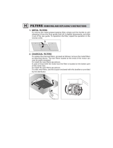
3 - 4 Air Cleaning Components. Use with (VH) models.
Figure 5
(insert picture, includes #1charcoal filter, #2 electronic air cleaner, and #3 baffle filter)
ITEM DESCRIPTION FUNCTION
1. Fig. 4 & 5 Charcoal Filter The Charcoal Filter helps to remove odor generated
(Replaced MONTHLY) during cooking. This comprises the third and final stage
of the air filtration system used in the Ventless Hood
System. It is mounted in a slide-rack directly above the
EAC. Disconnect fryer power before removing this
filter. NEVER attempt to clean a Charcoal Filter. Keep a
spare filter on hand (Giles P/N# 30248) for a quick
change-out when needed!
2. Fig. 4 Electronic Air Cleaner (EAC) The EAC is an electrical device which removes grease
(Cleaned DAILY) vapor and smoke generated by the fryer during cooking.
The access panel on the front of the upper hood portion
must be removed to allow for access to the cell.
Power must be turned OFF to the fryer before
removing the EAC for cleaning.
The EAC should be cleaned daily.
3. Fig. 4 & 5 Baffle Filter The Baffle Filter is the first stage of the three-part
(Cleaned DAILY) grease extraction and air-cleaning system found on
these units. It is easily removed for daily cleaning.
DO NOT remove the Baffle Filter while the fryer is
operating to prevent contact with electrical parts and
avoid electrical shock.
1 2
3

Testing the Fryer
16
4 Testing the Fryer
We at Giles take pride in the quality of out workmanship. Every effort has been made to ensure your unit
is in good operating condition when you receive it. Each unit must pass a rigorous quality control test prior
to shipment. To further ensure optimum operation of your new unit, we recommend a brief operational
check-out of your new fryer.
CAUTION
Before attempting to operate the unit, refer to Section 3 to familiarize yourself with the
various control functions. Once you have read and fully understand Section 3, please
follow the steps below precisely in order to prevent equipment damage or malfunction.
4 - 1 Proper Control Settings for Check -Out
1. Place all switches in the “OFF” position.
2. Remove Fryer lid.
3. Remove the baskets or other accessory items from the fry-kettle.
4. Turn on the circuit breaker which supplies power to the unit.
5. Place the fryer’s main Power Switch to “ON”. The green power light should be illuminated. If the
power light fails to illuminate, refer to the appropriate section of the troubleshooting guide. If the
green power light illuminates, proceed to the next step.
!

4 - 2 Operational Check of Heating Elements
This step is designed to ensure your fryer
’
s Heating Elements are functioning.
WARNING
DO NOT touch the Heating Elements during this portion of the check-out. The Heating
Elements are very hot and skin contact with them may result in severe burns.
1. Wipe the dry cool Heating Elements with a wet sponge.
CAUTION
This portion of the check-out requires the elements be activated. DO NOT operate
the elements for more than 10 seconds without them being fully covered by shortening.
Failure to observe this precaution may result in damage to the Heating Elements.
2. With the fryer’s lid removed, briefly turn the Selector Switch to the “COOK” position (max. 10 sec.).
Then return it to the “OFF” position.
3. The wet element should dry within 15 seconds after fryer element shut-off signifying heat.
4. If the elements do not appear operational, refer to the troubleshooting guide.
5. If the Heating Elements are operational, clean the fryer as described under instructions for the boil-out
procedure described in this manual.
6. After thorough cleaning, fill fry pot to proper level with shortening.
17
Testing the Fryer
!
!

Testing the Fryer
18
4 - 3 Operational Check-Out of WOG-VH-D Filter Pan Heating System
1. Open the Fryer’s front door.
2. Disconnect the Filter-Pan Hose by using the Quick-Disconnect fitting.
3. Remove the Filter Pan by sliding it forward.
4. Ensure the pump switch is in the “OFF” position.
5. Place the Selector Switch in the “FILTER” position.
6. Place the fryer’s Power Switch to the “ON” position.
7. Wipe the dry, cool heating element with a WET sponge.
8. Set the Filter Pan heat timer to one (1) minute.
9. The wet Heating Element should dry within fifteen (15) seconds after the fryer element shut off
signifying heat.
10. The Filter Pan heating system is working properly if the Heating Element is dry.
4 - 4 Operational Check-Out of the Filter Pump
1. Open the fryer’s front door.
2. Disconnect the Filter-Pan hose by lifting the insulating ring on the Quick-Disconnect and pull the hose
out of this fitting.
CAUTION
The following step requires starting the fryer’s Filter Pump in a “DRY” condition. The
pump should only be operated for a few seconds in this manner or damage to the unit
will occur.
3. Place the fryer’s Power Switch to the “ON” position.
4. Place your palm over the Quick-Disconnect at the point where the nose from the Filter-Pan connects.
5. Briefly place the Selector Switch in the “FILTER” position. If suction is felt on the hand covering the
Quick-Disconnect, the pump is operational. If the above steps are followed and no suction is felt,
consult the troubleshooting guide.
!
/