Page is loading ...


The following copyright notice protects this book under Copyright laws which prohibit such actions as, but not limited
to, copying, distributing, modifying, and making derivative works.
Copyright © Bull SAS
2010-2011
Copyright © Super Micro Computer, Inc., 2009
Printed in France
Suggestions and criticisms concerning the form, content, and presentation of this book are
invited. A form is provided at the end of this book for this purpose.
To order additional copies of this book or other Bull Technical Publications, you are invited
to use the Ordering Form also provided at the end of this book.
Trademarks and Acknowledgements
We acknowledge the rights of the proprietors of the trademarks mentioned in this manual.
All brand names and software and hardware product names are subject to trademark and/or patent protection.
Quoting of brand and product names is for information purposes only and does not represent trademark misuse.
Intel® and Xeon® are registered trademarks of Intel Corporation.
Windows® and Microsoft® software are registered trademarks of Microsoft Corporation.
Linux® is a registered trademark of Linus Torwalds.
Phoenix® is a registered trademark of Phoenix Technologies.
The information in this document is subject to change without notice. Bull will not be liable for errors
contained herein, or for incidental or consequential damages in connection with the use of this material.

III
Preface
About This Manual
This manual is written for professional system integrators and PC technicians. It
provides information for the installation and use of the bullx R424-E2/R424-INF-
E2 or the bullx R424-F2/R424-INF-F2. Installation and maintenance should be
performed by experienced technicians only.
The bullx R424-E2/R424-INF-E2 and R424-F2/R424-INF-F2 are 2U Bi-Twin
(four serverboards in a 2U chassis) rackmount server chassis and two R424-E2/
R424-INF-E2 or R424-F2/R424-INF-F2 serverboards. The R424-E2/R424-INF-E2
and R424-F2/R424-INF-F2 serverboards support Intel® 5500 Series Processor
(Nehalem) and Intel® 5600 Series Processor (Westmere).
Manual Organization
Chapter 1: Introduction
The fi rst chapter provides a checklist of the main components included with the
server system and describes the main features of the bullx R424-E2/R424-INF-E2
and R424-F2/R424-INF-F2 serverboards and the bullx R424-E2/R424-INF-E2 and
R424-F2/R424-INF-F2 chassis.
Chapter 2: Server Installation
This chapter describes the necessary steps to install the bullx R424-E2/R424-INF-
E2 or R424-F2/R424-INF-F2 into a rack and check out the server confi guration
prior to powering up the system. If your server was ordered without the processor
and memory components, this chapter will refer you to the appropriate sections
of the manual for their installation.
Chapter 3: System Interface
Refer to this chapter for details on the system interface, which includes the func-
tions and information provided by the control panel on the chassis as well as other
LEDs located throughout the system.
Preface

IV
bullx R424-E2/R424-INF-E2 and R424-F2/R424-INF-F2 Installation and User's Guide
Chapter 4: System Safety
You should thoroughly familiarize yourself with this chapter for a general overview
of safety precautions that should be followed when installing and servicing the
bullx R424-E2/R424-INF-E2 and R424-F2/R424-INF-F2.
Chapter 5: Advanced Serverboard Setup
Chapter 5 provides detailed information on the R424-E2/R424-INF-E2 and
R424-F2/R424-INF-F2 serverboards, including the locations and functions of con-
nectors, headers and jumpers. Refer to this chapter when adding or removing
processors or main memory and when reconfi guring the serverboard.
Chapter 6: Advanced Chassis Setup
Refer to Chapter 6 for detailed information on the R424-E2/R424-INF-E2 and
R424-F2/R424-INF-F2 1U rackmount server chassis. You should follow the
procedures given in this chapter when installing, removing or reconfi guring SAS/
SATA or peripheral drives and when replacing system power supply units and
cooling fans.
Chapter 7: BIOS
The BIOS chapter includes an introduction to BIOS and provides detailed informa-
tion on running the CMOS Setup Utility.
Appendix A: BIOS Error Beep Codes
Appendix B: Intel HostRAID Setup Guidelines
Appendix C: Adaptec HostRAID Setup Guidelines
Appendix D: System Specifi cations

V
Table of Contents
Chapter 1. Introduction
1-1 Overview .....................................................................................................1-1
1-2 Serverboard Features ................................................................................1-2
CPU.......................................................................................................1-2
Memory .................................................................................................1-2
Onboard SAS (R424-F2/R424-INF-F2 only) .........................................1-2
Chipset ..................................................................................................1-2
Expansion Slot ......................................................................................1-2
BIOS......................................................................................................1-3
PC health Monitoring ............................................................................1-3
ACPI Features ...................................................................................... 1-3
Onboard I/O ..........................................................................................1-3
Graphics Controller ............................................................................... 1-4
Other .....................................................................................................1-4
CD/Diskette Utilities .............................................................................. 1-4
Dimensions ........................................................................................... 1-4
1-3 Chassis Components .................................................................................1-6
Overview ...............................................................................................1-6
Components ..........................................................................................1-6
Chapter 2. Server Installation
2-1 Overview .....................................................................................................2-1
2-2 Unpacking the System ............................................................................... 2-1
2-3 Preparing for Setup ....................................................................................2-1
Choosing a Setup Location ..................................................................2-1
Rack Precautions .................................................................................. 2-2
Server Precautions ............................................................................... 2-2
Rack Mounting Considerations .............................................................2-3
Ambient Operating Temperature ....................................................... 2-3
Reduced Airfl ow ................................................................................2-3
Mechanical Loading .......................................................................... 2-3
Circuit Overloading ........................................................................... 2-3
Reliable Ground ................................................................................ 2-3
Table of Contents

VI
2-4 Installing the System into a Rack .............................................................. 2-4
Identifying the Sections of the Rack Rails ............................................2-4
Locking Tabs ......................................................................................... 2-5
Releasing the Inner Rail ....................................................................... 2-5
Releasing Inner Rail from the Outer Rails ....................................... 2-5
Installing The Inner Rails on the Chassis .............................................2-6
Installing the Inner Rails ................................................................... 2-6
Installing The Outer Rails on the Rack.................................................2-7
Installing the Outer Rails .................................................................. 2-7
Standard Chassis Installation ...............................................................2-8
Installing the Chassis into a Rack .................................................... 2-8
Optional Quick Installation Method .....................................................2-10
Installing the Chassis into a Rack .................................................. 2-10
2-5 Checking the Serverboard Setup ..............................................................2-11
2-6 Preparing to Power On ............................................................................ 2-12
2-7 Chassis Cover ..........................................................................................2-13
Removing the Chassis Cover and Protective Film ......................... 2-13
Chapter 3. System Interface
3-1 Overview .....................................................................................................3-1
3-2 Control Panel Buttons ................................................................................3-2
3-3 Control Panel LEDS ................................................................................... 3-2
3-4 Drive Carrier LEDS ....................................................................................3-3
SAS/SATA Drives .................................................................................. 3-3
SCSI Drives ..........................................................................................3-3
Chapter 4. System Safety
4-1 Electrical Safety Precautions ..................................................................... 4-1
4-2 General Safety Precautions ....................................................................... 4-2
4-3 ESD Precautions ........................................................................................ 4-3
4-4 Operating Precautions ................................................................................ 4-4
Chapter 5. Advanced Serverboard Setup
5-1 Handling the Serverboard .......................................................................... 5-1
Precautions ...........................................................................................5-1
5-2 Installing the Serverboard ..........................................................................5-2
Permanent and Optional Standoffs.......................................................5-2
Unpacking .............................................................................................5-2
Installing the Serverboard ..................................................................... 5-3
bullx R424-E2/R424-INF-E2 and R424-F2/R424-INF-F2 Installation and User's Guide

VII
5-3 Connecting Cables ..................................................................................... 5-4
Connecting Data Cables ....................................................................... 5-4
Connecting Power Cables ....................................................................5-4
Connecting the Control Panel ............................................................... 5-5
5-4 Control Panel Connectors/IO Ports ............................................................ 5-6
5-5 Installing Processor and Heat Sink ............................................................ 5-7
Installing an LGA 1366 Processor .......................................................5-7
Installing a CPU Heatsink .................................................................... 5-9
Removing the Heatsink ..................................................................... 5-10
5-6 Installing Memory ......................................................................................5-11
Installing a DIMM .................................................................................5-11
Memory Support ............................................................................. 5-12
Nehalem DIMM Module Population Confi guration .........................5-12
Westmere DIMM Module Population Confi guration ....................... 5-12
Installing and Removing DIMMs ..................................................... 5-13
5-7 Installing and Replacing Adapter Cards ................................................... 5-14
Removing the Adapter Card ...............................................................5-14
Add-on Card/Expansion Slot Setup .................................................... 5-15
Installing the Riser Card ..................................................................... 5-16
Installing Add-on Cards ....................................................................... 5-17
5-8 Serverboard Details .................................................................................. 5-18
R424-E2 Quick Reference ................................................................. 5-21
R424-F2 Quick Reference .................................................................. 5-23
Serverboard Features ......................................................................... 5-24
CPU ................................................................................................ 5-24
Memory ...........................................................................................5-24
Chipset ............................................................................................5-24
Expansion Slot ................................................................................ 5-24
BIOS ............................................................................................... 5-24
ACPI Features ................................................................................ 5-25
Onboard I/O .................................................................................... 5-25
Other ...............................................................................................5-25
Dimensions .....................................................................................5-25
5-9 Back Panel Connector Pin Defi nitions ..................................................... 5-26
5-10 Front Panel Accessible Add-on Card Header (JF2) ................................. 5-31
5-11 Connecting Cables. ..................................................................................5-32
5-12 Jumper Settings .......................................................................................5-35
5-13 Onboard Indicators ................................................................................... 5-38
Table of Contents

VIII
5-14 Serial ATA and PCI-E Connections ..........................................................5-42
Chapter 6. Advanced Chassis Setup
6-1 Static-Sensitive Devices .............................................................................6-1
Precautions ...........................................................................................6-1
Unpacking .............................................................................................6-1
Chassis view for R424-E2 and R424-INF-E2 ....................................... 6-2
Chassis view for R424-F2 and R424-INF-F2 ....................................... 6-2
6-2 Installing and Removing Hard Drives on R424-E2 and R424-INF-E2 .......6-3
Removing Hard Drive Trays from the Chassis ................................. 6-4
Installing a Drive into the Hard Drive Tray ....................................... 6-6
6-3 Installing and Removing Hard Drives on R424-F2 and R424-INF-F2 .......6-7
Overview ...............................................................................................6-7
Installing and Removing Hard Drives ................................................... 6-7
Mounting a Hard Drive in a Carrier .................................................. 6-7
Installing/Removing Hot-swap Drives ............................................... 6-8
6-4 Removing and Installing the Backplane ................................................... 6-10
Removing the Backplane .................................................................... 6-10
Removing the Backplane from the Chassis ................................... 6-10
Installing the Backplane ...................................................................... 6-12
Installing the Backplane into the Chassis.......................................6-12
6-5 Installing the Serverboard ........................................................................6-13
Permanent and Optional Standoffs.....................................................6-13
Installing the Serverboard ................................................................... 6-14
6-6 Installing the Air Shrouds .........................................................................6-16
Installing an Air Shroud ....................................................................... 6-16
6-7 Checking the Air Flow ..............................................................................6-18
Checking Airfl ow .................................................................................6-18
Installation Complete .......................................................................... 6-18
6-8 Replacing System Fans ........................................................................... 6-18
Optional Fan Confi gurations ...............................................................6-18
Changing a System Fan ..................................................................... 6-20
6-9 Power Supply ...........................................................................................6-21
Power Supply Replacement ............................................................... 6-21
Changing the Power Supply ........................................................... 6-22
bullx R424-E2/R424-INF-E2 and R424-F2/R424-INF-F2 Installation and User's Guide

IX
Chapter 7. Troubleshooting
Before Power On .................................................................................. 7-1
No Power ..............................................................................................7-1
No Video ...............................................................................................7-2
Losing the System’s Setup Confi guration ............................................. 7-2
Memory Errors ...................................................................................... 7-2
Chapter 8. BIOS
8-1 Introduction .................................................................................................8-1
8-2 Main Setup .................................................................................................8-2
8-3 Advanced Setup Confi gurations .................................................................8-4
8-4 Security Settings ......................................................................................8-26
8-5 Boot Confi guration .................................................................................... 8-27
8-6 Exit............................................................................................................8-28
8-7 BIOS Recovery ......................................................................................... 8-30
How to Recover the AMIBIOS Image (-the Main BIOS Block) .......... 8-30
Boot Sector Recovery from a USB Device.........................................8-30
Boot Sector Recovery from an IDE CD-ROM .................................... 8-31
Boot Sector Recovery from a Serial Port ("Serial Flash") .................. 8-31
Requirements ......................................................................................8-31
How to use Serial Flash for Boot Sector Recovery ............................ 8-31
Appendix A. BIOS Error Beep Codes
A-1 BIOS Error Beep Codes .............................................................................A-1
Appendix B. Intel HostRAID Setup Guidelines
Appendix C. Adaptec HostRAID Setup Guidelines
Appendix D. System Specifi cations
Table of Contents

X
bullx R424-E2/R424-INF-E2 and R424-F2/R424-INF-F2 Installation and User's Guide

Chapter 1. Introduction
1-1 Overview
The bullx R424-E2/R424-INF-E2 and R424-F2/R424-INF-F2 are "2U Bi-Twin"
servers comprised of the 2U chassis and four (bi-twin) R424-E2/R424-INF-E2 and
R424-F2/R424-INF-F2 serverboards. Please refer to our web site for information
on operating systems that have been certifi ed for use with the bullx R424-E2/R424-
INF-E2 and R424-F2/R424-INF-F2.
In addition to the serverboard and chassis, various hardware components may have
been included with the bullx R424-E2/R424-INF-E2 and R424-F2/R424-INF-F2, as
listed below.
Eight (8) CPU heatsinks (SNK-P0037P)
•
On server R424-E2/R424-INF-E2:
SATA Accessories:
•
Twelve (12) Hot-swappable Hard Drive Trays (MCP-220-00024-0B)
One (1) Hot Swap Backplane (BPN-SAS827B)
One (1) SATA cable set (CBL-0180L-01)
On server R424-F2/R424-INF-F2:
SAS/SATA Accessories:
•
Twenty-four (24) Hard Drive carriers (six per node) (MCP-220-00075-0B)
One (1) Internal HDD Backplane (BPN-SAS-217HQ)
Four (4) SAS Daughter Cards, BPN-ADP-SAS2-H8iR).
Four (4) 80x35MM 9.5K RPM 4-PIN PWM fans (FAN-0111L4)
•
Rail set, quick/quick, for 2, 3U (MCP-290-00053-ON) •
One (1) CD containing drivers and utilities •
Chapter 1: Introduction
1-1

1-2
bullx R424-E2/R424-INF-E2 and R424-F2/R424-INF-F2 Installation and User's Guide
1-2 Serverboard Features
At the heart of the bullx R424-E2/R424-INF-E2 and R424-F2/R424-INF-F2 lies
four R424-E2/R424-INF-E2 or R424-F2/R424-INF-F2 dual processor serverboards,
which are based on Intel's S5520 chipset (Tylersburg IOH-36D). Below are the
main features of the bullx R424-E2/R424-INF-E2 and R424-F2/R424-INF-F2 ser-
verboards. Note that the features on each board are doubled for the server.
CPU
Intel® Xeon® 5500 series processors (code-named Nehalem EP) or Intel® •
Xeon® 5600 series processors (code-named Westmere EP) with each
processor supporting two full-width Intel QuickPath Interconnect (QPI) links
with a total of up to 51.2 GT/s Data Transfer Rate supported (6.4 GT/s per
direction).
Memory
Twelve 240-pin DIMM sockets maxi:•
with Westmere processor, up to 192 GB of Registered ECC DDR3 •
1066 MHz or up to 96 GB of Registered ECC DDR3 1333 MHz,
or
with Nehalem processor, up to 96 GB of Registered ECC DDR3 •
1066 MHz or up to 48 GB of Registered ECC DDR3 1333 MHz
Onboard SAS (R424-F2/R424-INF-F2 only)
An LSI 2108 SAS controller is integrated into a daughter card to provide •
six SAS ports per node. The hot-swap SAS drives are connected to a
backplane that provides power, bus termination, and confi guration settings.
Note: The operating system you use must have RAID support to enable
the hot-swap capability and RAID function of the SAS drives. RAID 0, 1, 5
and 10 and 6 are supported.
Chipset
Intel 5520 chipset, including: the 5520 (IOH-36D) and the ICH10R (South •
Bridge).
Expansion Slot
One PCI-E x16 Gen. 2.0 slot (Slot 1).•

Chapter 1: Introduction
1-3
BIOS
32 Mb AMI SPI Flash ROM.•
ACPI 1.0/2.0/3.0, Plug and Play (PnP), and USB Keyboard support.•
PC health Monitoring
Onboard voltage monitors for CPU1 VCore, CPU2 VCore, +5Vin, 12Vcc •
(V), VP1 DIMM, VP2 DIMM, +3.3Vcc (V), and Battery Voltage.
Fan status monitor with fi rmware control.•
CPU/chassis temperature monitors.•
I2C temperature sensing logic.•
SDDC support.•
Platform Environment Control Interface (PECI) ready.•
CPU fan auto-off in sleep mode.•
CPU slow-down on temperature overheat.•
Pulse Width Modulation (PWM) Fan Control.•
CPU thermal trip support for processor protection, power LED.•
Power-up mode control for recovery from AC power loss.•
Auto-switching voltage regulator for CPU cores.•
System overheat/Fan Fail LED Indicator and control.•
ACPI Features
Slow blinking LED for suspend state indicator.•
Main switch override mechanism.•
ACPI Power Management.•
Keyboard Wakeup from Soft-off.•
Onboard I/O
Intel ICH10R supports a SATA port (with RAID0, RAID1, RAID10, RAID5 •
supported in the Windows OS Environment and RAID 0, RAID 1, RAID 10
supported for the Linux OS).
Winbond WPCM450 BMC (Baseboard Management Controller) supports •
IPMI 2.0 with KVM support.

1-4
bullx R424-E2/R424-INF-E2 and R424-F2/R424-INF-F2 Installation and User's Guide
Dual Intel 82574 Dual-LAN Gigabit Ethernet Controllers support dual Giga-•
bit LAN ports.
Onboard PHY Chip supports IPMI dedicated LAN.•
One COM port.•
Infi niBand Connector.•
Up to four USB 2.0 (Universal Serial Bus) connections (2 Rear USB Ports •
and 1 Type A Header w/2 USB connections supported).
Super I/O: Winbond W83527HG.•
Graphics Controller
The serverboard features an integrated Matrox G200eW graphics chip, •
which includes 16MB of DDr2 memory.
Other
Console redirection.•
Onboard Fan Speed Control by Thermal Management via BIOS.•
CD/Diskette Utilities
Device drivers and documentation.•
Dimensions
Proprietary 16.64" (L) x 6.80" (W) (422.66 mm x 172.72 mm).•

Chapter 1: Introduction
1-5
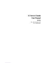
Figure 1-1. System Block Diagram
Note: This is a general block diagram. See the Motherboard Features pages for
details on the features of each motherboard.

1-6
bullx R424-E2/R424-INF-E2 and R424-F2/R424-INF-F2 Installation and User's Guide
1-3 Chassis Components
Overview
This chapter describes the most common components included with your chassis.
Some components listed may not be included or compatible with your particular
chassis model. For more information, see the installation instructions detailed later
in this manual.
Components
Chassis
The bullx R424-E2 chassis includes twelve 3.5" hot-swappable hard drive •
bays.
The bullx R424-F2 chassis includes twenty-four 2.5" hot-swappable hard •
drive bays.
Backplanes and Riser Cards
The bullx R424-E2 chassis comes equipped with a BPN-SAS-827B back-•
plane and a BPN-827ADP-XB-H as a Riser Card.
The bullx R424-F2 chassis comes equipped with a BPN-SAS-217HQ •
backplane and a BPN-ADP-SAS2-H6IR as a SAS backplane Riser Card
6 x SAS2 LSI 2108..
Fans
The bullx R424-E2 and R424-F2 chassis accept four system fans. System •
fans for the chassis are powered from the motherboards or the HDD back-
plane. The two fans on each side are controlled by two motherboards, so
that when one of the motherboard nodes is removed, the second mother-
board will continue to control both fans.
Power Supply
The bullx R424-E2 and R424-F2 chassis models include a high-effi ciency •
80 Plus Gold Level power supply, rated at 1400 Watts. In the unlikely event
your power supply fails, replacement is simple and can be accomplished
without tools.

Chapter 1: Introduction
1-7
Air Shroud
The bullx R424-E2 and R424-F2 chassis require mylar air shrouds for each •
node to direct the airfl ow where cooling is needed.

1-8
bullx R424-E2/R424-INF-E2 and R424-F2/R424-INF-F2 Installation and User's Guide
Notes
/