Page is loading ...

WindoWall
™
System
MGP 464W, MGP 464W DI
WindoWall Processors
68-1481-01 Rev. B
06 08

This symbol is intended to alert the user of important operating and maintenance
(servicing) instructions in the literature provided with the equipment.
This symbol is intended to alert the user of the presence of uninsulated dangerous
voltage within the product’s enclosure that may present a risk of electric shock.
Caution
Read Instructions • Read and understand all safety and operating instructions before using the equipment.
Retain Instructions • The safety instructions should be kept for future reference.
Follow Warnings • Follow all warnings and instructions marked on the equipment or in the user
information.
Avoid Attachments • Do not use tools or attachments that are not recommended by the equipment
manufacturer because they may be hazardous.
Warning
Power sources • This equipment should be operated only from the power source indicated on the product. This
equipment is intended to be used with a main power system with a grounded (neutral) conductor. The
third (grounding) pin is a safety feature, do not attempt to bypass or disable it.
Power disconnection • To remove power from the equipment safely, remove all power cords from the rear of
the equipment, or the desktop power module (if detachable), or from the power source receptacle (wall
plug).
Power cord protection • Power cords should be routed so that they are not likely to be stepped on or pinched by
items placed upon or against them.
Servicing • Refer all servicing to qualified service personnel. There are no user-serviceable parts inside. To
prevent the risk of shock, do not attempt to service this equipment yourself because opening or removing
covers may expose you to dangerous voltage or other hazards.
Slots and openings • If the equipment has slots or holes in the enclosure, these are provided to prevent
overheating of sensitive components inside. These openings must never be blocked by other objects.
Lithium battery • There is a danger of explosion if battery is incorrectly replaced. Replace it only with the
same or equivalent type recommended by the manufacturer. Dispose of used batteries according to the
manufacturer’s instructions.
Ce symbole sert à avertir l’utilisateur que la documentation fournie avec le matériel
contient des instructions importantes concernant l’exploitation et la maintenance
(réparation).
Ce symbole sert à avertir l’utilisateur de la présence dans le boîtier de l’appareil
de tensions dangereuses non isolées posant des risques d’électrocution.
Attention
Lire les instructions• Prendre connaissance de toutes les consignes de sécurité et d’exploitation avant
d’utiliser le matériel.
Conserver les instructions• Ranger les consignes de sécurité afin de pouvoir les consulter à l’avenir.
Respecter les avertissements • Observer tous les avertissements et consignes marqués sur le matériel ou
présentés dans la documentation utilisateur.
Eviter les pièces de xation • Ne pas utiliser de pièces de fixation ni d’outils non recommandés par le
fabricant du matériel car cela risquerait de poser certains dangers.
Avertissement
Alimentations• Ne faire fonctionner ce matériel qu’avec la source d’alimentation indiquée sur l’appareil. Ce
matériel doit être utilisé avec une alimentation principale comportant un fil de terre (neutre). Le troisième
contact (de mise à la terre) constitue un dispositif de sécurité : n’essayez pas de la contourner ni de la
désactiver.
Déconnexion de l’alimentation• Pour mettre le matériel hors tension sans danger, déconnectez tous les cordons
d’alimentation de l’arrière de l’appareil ou du module d’alimentation de bureau (s’il est amovible) ou
encore de la prise secteur.
Protection du cordon d’alimentation • Acheminer les cordons d’alimentation de manière à ce que personne ne
risque de marcher dessus et à ce qu’ils ne soient pas écrasés ou pincés par des objets.
Réparation-maintenance • Faire exécuter toutes les interventions de réparation-maintenance par un technicien
qualifié. Aucun des éléments internes ne peut être réparé par l’utilisateur. Afin d’éviter tout danger
d’électrocution, l’utilisateur ne doit pas essayer de procéder lui-même à ces opérations car l’ouverture ou le
retrait des couvercles risquent de l’exposer à de hautes tensions et autres dangers.
Fentes et orices • Si le boîtier de l’appareil comporte des fentes ou des orifices, ceux-ci servent à empêcher
les composants internes sensibles de surchauffer. Ces ouvertures ne doivent jamais être bloquées par des
objets.
Lithium Batterie • Il a danger d’explosion s’ll y a remplacment incorrect de la batterie. Remplacer uniquement
avec une batterie du meme type ou d’un ype equivalent recommande par le constructeur. Mettre au reut les
batteries usagees conformement aux instructions du fabricant.
Safety Instructions • English
Consignes de Sécurité • Français
Sicherheitsanleitungen • Deutsch
Dieses Symbol soll dem Benutzer in der im Lieferumfang enthaltenen
Dokumentation besonders wichtige Hinweise zur Bedienung und Wartung
(Instandhaltung) geben.
Dieses Symbol soll den Benutzer darauf aufmerksam machen, daß im Inneren des
Gehäuses dieses Produktes gefährliche Spannungen, die nicht isoliert sind und
die einen elektrischen Schock verursachen können, herrschen.
Achtung
Lesen der Anleitungen • Bevor Sie das Gerät zum ersten Mal verwenden, sollten Sie alle Sicherheits-und
Bedienungsanleitungen genau durchlesen und verstehen.
Aufbewahren der Anleitungen • Die Hinweise zur elektrischen Sicherheit des Produktes sollten Sie
aufbewahren, damit Sie im Bedarfsfall darauf zurückgreifen können.
Befolgen der Warnhinweise • Befolgen Sie alle Warnhinweise und Anleitungen auf dem Gerät oder in der
Benutzerdokumentation.
Keine Zusatzgeräte • Verwenden Sie keine Werkzeuge oder Zusatzgeräte, die nicht ausdrücklich vom
Hersteller empfohlen wurden, da diese eine Gefahrenquelle darstellen können.
Vorsicht
Stromquellen • Dieses Gerät sollte nur über die auf dem Produkt angegebene Stromquelle betrieben werden.
Dieses Gerät wurde für eine Verwendung mit einer Hauptstromleitung mit einem geerdeten (neutralen)
Leiter konzipiert. Der dritte Kontakt ist für einen Erdanschluß, und stellt eine Sicherheitsfunktion dar. Diese
sollte nicht umgangen oder außer Betrieb gesetzt werden.
Stromunterbrechung • Um das Gerät auf sichere Weise vom Netz zu trennen, sollten Sie alle Netzkabel
aus der Rückseite des Gerätes, aus der externen Stomversorgung (falls dies möglich ist) oder aus der
Wandsteckdose ziehen.
Schutz des Netzkabels • Netzkabel sollten stets so verlegt werden, daß sie nicht im Weg liegen und niemand
darauf treten kann oder Objekte darauf- oder unmittelbar dagegengestellt werden können.
Wartung • Alle Wartungsmaßnahmen sollten nur von qualiziertem Servicepersonal durchgeführt werden.
Die internen Komponenten des Gerätes sind wartungsfrei. Zur Vermeidung eines elektrischen Schocks
versuchen Sie in keinem Fall, dieses Gerät selbst öffnen, da beim Entfernen der Abdeckungen die Gefahr
eines elektrischen Schlags und/oder andere Gefahren bestehen.
Schlitze und Öffnungen • Wenn das Gerät Schlitze oder Löcher im Gehäuse aufweist, dienen diese zur
Vermeidung einer Überhitzung der empndlichen Teile im Inneren. Diese Öffnungen dürfen niemals von
anderen Objekten blockiert werden.
Litium-Batterie • Explosionsgefahr, falls die Batterie nicht richtig ersetzt wird. Ersetzen Sie verbrauchte
Batterien nur durch den gleichen oder einen vergleichbaren Batterietyp, der auch vom Hersteller
empfohlen wird. Entsorgen Sie verbrauchte Batterien bitte gemäß den Herstelleranweisungen.
Este símbolo se utiliza para advertir al usuario sobre instrucciones importantes
de operación y mantenimiento (o cambio de partes) que se desean destacar en el
contenido de la documentación suministrada con los equipos.
Este símbolo se utiliza para advertir al usuario sobre la presencia de elementos con
voltaje peligroso sin protección aislante, que puedan encontrarse dentro de la caja
o alojamiento del producto, y que puedan representar riesgo de electrocución.
Precaucion
Leer las instrucciones • Leer y analizar todas las instrucciones de operación y seguridad, antes de usar el
equipo.
Conservar las instrucciones • Conservar las instrucciones de seguridad para futura consulta.
Obedecer las advertencias • Todas las advertencias e instrucciones marcadas en el equipo o en la
documentación del usuario, deben ser obedecidas.
Evitar el uso de accesorios • No usar herramientas o accesorios que no sean especificamente recomendados
por el fabricante, ya que podrian implicar riesgos.
Advertencia
Alimentación eléctrica • Este equipo debe conectarse únicamente a la fuente/tipo de alimentación eléctrica
indicada en el mismo. La alimentación eléctrica de este equipo debe provenir de un sistema de distribución
general con conductor neutro a tierra. La tercera pata (puesta a tierra) es una medida de seguridad, no
puentearia ni eliminaria.
Desconexión de alimentación eléctrica • Para desconectar con seguridad la acometida de alimentación eléctrica
al equipo, desenchufar todos los cables de alimentación en el panel trasero del equipo, o desenchufar el
módulo de alimentación (si fuera independiente), o desenchufar el cable del receptáculo de la pared.
Protección del cables de alimentación • Los cables de alimentación eléctrica se deben instalar en lugares donde
no sean pisados ni apretados por objetos que se puedan apoyar sobre ellos.
Reparaciones/mantenimiento • Solicitar siempre los servicios técnicos de personal calicado. En el interior no
hay partes a las que el usuario deba acceder. Para evitar riesgo de electrocución, no intentar personalmente
la reparación/mantenimiento de este equipo, ya que al abrir o extraer las tapas puede quedar expuesto a
voltajes peligrosos u otros riesgos.
Ranuras y aberturas • Si el equipo posee ranuras o orificios en su caja/alojamiento, es para evitar el
sobrecalientamiento de componentes internos sensibles. Estas aberturas nunca se deben obstruir con otros
objetos.
Batería de litio • Existe riesgo de explosión si esta batería se coloca en la posición incorrecta. Cambiar esta
batería únicamente con el mismo tipo (o su equivalente) recomendado por el fabricante. Desachar las
baterías usadas siguiendo las instrucciones del fabricante.
Instrucciones de seguridad • Español
Precautions
安全须知 • 中文
这个符号提示用户该设备用户手册中有重要的操作和维护说明。
这个符号警告用户该设备机壳内有暴露的危险电压,有触电危险。
注意
阅读说明书 • 用户使用该设备前必须阅读并理解所有安全和使用说明。
保存说明书 • 用户应保存安全说明书以备将来使用。
遵守警告 • 用户应遵守产品和用户指南上的所有安全和操作说明。
避免追加 • 不要使用该产品厂商没有推荐的工具或追加设备,以避免危险。
警告
电源 • 该设备只能使用产品上标明的电源。 设备必须使用有地线的供电系统供电。 第三条线
(地线)是安全设施,不能不用或跳过 。
拔掉电源 • 为安全地从设备拔掉电源,请拔掉所有设备后或桌面电源的电源线,或任何接到市
电系统的电源线。
电源线保护 • 妥善布线, 避免被踩踏,或重物挤压。
维护 • 所有维修必须由认证的维修人员进行。 设备内部没有用户可以更换的零件。为避免出
现触电危险不要自己试图打开设备盖子维修该设备。
通风孔 • 有些设备机壳上有通风槽或孔,它们是用来防止机内敏感元件过热。 不要用任何东
西挡住通风孔。
锂电池 • 不正确的更换电池会有爆炸的危险。必须使用与厂家推荐的相同或相近型号的电池。
按照生产厂的建议处理废弃电池。

FCC Class A Notice
This equipment has been tested and found to comply with the limits for a Class A digital device, pursuant
to part 15 of the FCC Rules. Operation is subject to the following two conditions: (1) this device may
not cause harmful interference, and (2) this device must accept any interference received, including
interference that may cause undesired operation. The Class A limits are designed to provide reasonable
protection against harmful interference when the equipment is operated in a commercial environment.
This equipment generates, uses, and can radiate radio frequency energy and, if not installed and used
in accordance with the instruction manual, may cause harmful interference to radio communications.
Operation of this equipment in a residential area is likely to cause harmful interference, in which case the
user will be required to correct the interference at his own expense.
N
This unit was tested with shielded cables on the peripheral devices. Shielded cables must be used with the
unit to ensure compliance with FCC emissions limits.
声明
所使用电源为 A 级产品,在生活环境中,该产品可能会造成无线电干扰。在这
种情况下,可能需要用户对其干扰采取切实可行的措施。


i
MGP 464W • Table of Contents
PRELIMINARY
Table of Contents
Chapter One • Introduction ......................................................................................................1-1
About This Manual .................................................................................................................... 1-2
About the MGP 464W WindoWall Processor..............................................................1-2
Features ............................................................................................................................................1-2
Application Diagram ................................................................................................................1-4
Chapter Two • Installation and Operation ....................................................................2-1
Installation Overview ..............................................................................................................2-2
Mounting the MGP 464W ......................................................................................................2-2
Tabletop use ...............................................................................................................................2-2
Rack mounting .......................................................................................................................... 2-2
UL guidelines for rack mounting ............................................................................... 2-2
Rack mounting procedure .......................................................................................... 2-3
Rear Panel Features ..................................................................................................................2-4
Front Panel ..................................................................................................................................... 2-7
Resetting ......................................................................................................................................... 2-7
Chapter Three • Software-based Configuration and Control ........................ 3-1
Setting Up the WindoWall
™
Console Software ........................................................3-2
Installing and starting the software .......................................................................................3-2
Downloading the WindoWall Console program from the Web ........................................ 3-3
Starting up the WindoWall software .....................................................................................3-4
Setting up a WindoWall project .............................................................................................3-5
Using the Auto Image Wizard ...............................................................................................3-17
Setting Up RS-232/422 Communication ......................................................................3-19
Using Simple Instruction Set (SIS™) Commands ..................................................3-20
Host-to-MGP communications ..............................................................................................3-20
MGP-initiated messages .........................................................................................................3-20
Error responses ........................................................................................................................3-20
Telnet and Web communications .........................................................................................3-21
Symbol definitions ..................................................................................................................3-22
Chapter Four • Ethernet-based Configuration and Control ............................4-1
Accessing the Web Pages ......................................................................................................4-2
Viewing System Status ...........................................................................................................4-3
Using the Configuration Pages ..........................................................................................4-4
System Settings screen ............................................................................................................. 4-4
Passwords screen ....................................................................................................................... 4-5
Assigning a password .................................................................................................. 4-5
Clearing a password .................................................................................................... 4-5

Table of Contents, cont’d
MGP 464W • Table of Contents
ii
PRELIMINARY
Email Alerts screen ....................................................................................................................4-6
Setting up e-mail alerts ............................................................................................... 4-6
Setting up SMTP authorization .................................................................................. 4-7
Firmware Upgrade screen ........................................................................................................4-7
Determining the current firmware version ............................................................... 4-8
Downloading the firmware file ................................................................................. 4-8
Updating the firmware on the MGP 464W .............................................................. 4-8
Using the File Management Page .................................................................................. 4-10
Uploading files ........................................................................................................................ 4-10
Adding a directory ..................................................................................................................4-11
Other file management activities .........................................................................................4-11
Chapter Five • Special Application: Edge Blending ...............................................5-1
Example of a System Using Edge Blending ...............................................................5-3
Example of an Edge-matched System ...........................................................................5-4
Setting up the WindoWall Console Software for Edge Blending ................5-5
Appendix A • Reference Material ........................................................................................ A-1
Specifications .............................................................................................................................. A-2
Part Numbers and Accessories .......................................................................................... A-4
Included parts ........................................................................................................................... A-4
Optional accessories ................................................................................................................ A-4
Appendix B • Firmware Updates ...........................................................................................B-1
Determining the Current Firmware Version .............................................................B-2
Downloading a Firmware File ............................................................................................B-3
Updating the Firmware on the MGP 464W ...............................................................B-3
Updating using the Firmware Upgrade Web page ..............................................................B-3
Updating using the Firmware Loader ....................................................................................B-4
All trademarks mentioned in this manual are the properties of their respective owners.
68-1481-01 B
06 08

PRELIMINARY
MGP 464W WindoWall Processor
1
Chapter One
Introduction
About This Manual
About the MGP 464W WindoWall Processor
Features
Application Diagram

MGP 464W • Introduction
1-2
Introduction
PRELIMINARY
About this Manual
This manual discusses how to install, configure, and operate the Extron MGP 464W
WindoWall processor.
Throughout this manual, the terms “MGP 464W,” “MGP,” and “processor” are used
interchangeably to refer to the same products, both standard and DVI versions.
About the MGP 464W WindoWall Processor
The MGP 464W and MGP 464W DI are four-window RGB and video signal
processors designed for WindoWall video wall systems. Each MGP 464W can
display up to four video sources on a single screen in picture-in-picture or picture-
by-picture format. The MGP accepts RGB, HDTV, component, S-video, and
composite video signals on four fully-configurable inputs and has one scaled
output. The MGP processor provides switching among inputs and has picture
controls and presets, accessible via the WindoWall
™
Console software.
The MGP 464W DI is an MGP 464W with a DVI input card installed, providing four
DVI input connectors.
WindoWall uses a distributed video processing architecture that dedicates a
separate MGP 464W WindoWall processor to each output device (projector,
video cube, or flat panel monitor) in the video wall system. Each of the MGP’s
windows can show video, HDTV, or high resolution computer video content. The
MGP 464W is compatible with most available display devices and outputs video
at resolutions up to 1600x1200 and HDTV 1080p. Because a discrete, real-time
processor is dedicated to each display unit in the video wall, the WindoWall system
is fully scalable, supporting display layouts from 1x2 to 3x2 and larger.
WindoWall systems are available in sets of two or three processors, for 1x2 or 3x2
arrays, with or without DVI.
Features
Each MGP 464W WindoWall Processor features the following:
Scalable video wall multi-display support — Enables scalable video wall systems
from 1x2 to 3x2 and larger, on two or more displays.
Four windows — Up to four independent windows can be shown on a single
display simultaneously, allowing up to four video, HDTV, and high-resolution
computer video sources to be viewed at once on each MGP.
Inputs — The MGP 464W has four fully configurable video inputs, which accept
RGB, HDTV, component, S-video, and composite video signals. The
MGP 464W DI has four DVI inputs in addition.
DVI background input — A DVI input is provided on both models as a means to
display live high resolution computer or HDTV video from a DVI source as a
background to any presentation.
Output — The MGP 464W has one scaled output, available on a set of five BNC
connectors for RGB or component video, and a DVI-I connector for digital
video. The MGP 464W simultaneously outputs RGB computer video or
HDTV component video signals as analog and digital DVI. 48 selectable
output rates are available.
RGB and video scaling — All sources are scaled to a single output rate.

1-3
MGP 464W • Introduction
PRELIMINARY
Graphical user interface — The WindoWall Console application software is the
user interface for the WindoWall video wall system. It brings all of the
MGP 464W processors together via TCP/IP and provides the tools and
features to set up, create, and manage video wall presentations with up to
four windows per display or video cube unit. See chapter 3, “Software-based
Configuration and Control,” for information on installing and setting up the
Windowall software, which is provided with your WindoWall system. Refer
to the WindoWall Console software help file for detailed information on using
this software.
The WindoWall software enables you to enable and configure the following:
Picture controls — Picture controls allow you to adjust the size, position,
brightness, contrast, color, tint, detail, and zoom for each window. The
image within each window can be resized also, independently of its
window.
Text labels — Each picture-in-picture window can be labeled with up to 16
characters. These labels can be customized for positioning, text color,
character size, background, and border.
Window and input presets — Window presets save window sizing,
positioning, and priority information. Input presets save input signal
type information and picture control settings.
Freeze control — Freeze control freezes (locks) a window to the current
image.
Video wall virtual canvas — Virtual canvas enables on-screen video wall
visualization and dynamic window placement/sizing.
Background image management — Image files can be uploaded and stored
in memory on the MGP. You can then browse to these image files and
select them for use as the background image on the video wall canvas.
The MGP can store up to six high resolution images, enabling you to to
easiily display frequently used images such as a company logo.
Auto Image
™
— The Auto Image feature automatically sizes, centers, and optimizes
the image to the scaled output rate, filling the window.
Remote operation — WindoWall is operated remotely via the Ethernet interface,
using the WindoWall Console application.
Third party window preset recall — Window presets that were configured and
saved in the WindoWall Console application can later be recalled remotely
by user-friendly text strings issued to the primary MGP. The primary MGP
coordinates with the other MGPs and the matrix switcher to recall the preset
and the inputs that were displayed in the windows.
Internal test patterns — The MGP provides a range of 15 test patterns, including a
crop pattern, crosshatch, 16-bar grayscale, Color Bars, and patterns for setting
up side-by-side windows. It also features a blue-only mode for proper setup
of video color and tint levels.
Rack mounting — The 2U high and full rack wide metal enclosure can be rack
mounted using the included mounting brackets.
Internal international power supply — The 100-240 VAC, 50/60 Hz internal power
supply provides worldwide power compatibility.

Introduction, cont’d
MGP 464W • Introduction
1-4
PRELIMINARY
3:2 pulldown detection for NTSC video and 2:2 film detection for PAL — These
advanced film mode processing features help maximize image detail and
sharpness for video sources that originated from film.
When film is converted to NTSC video, the film frame rate has to be matched
to the video frame rate in a process called 3:2 pulldown. Jaggies and other
image artifacts can result if conventional deinterlacing techniques are used on
film-source video.
The MGP 464W’s advanced film mode processing recognizes signals that
originated from film. The MGP then applies video processing algorithms
that optimize the conversion of video made in the 3:2 pulldown process. This
results in richly detailed images with sharply defined lines.
A similar process, 2:2 film detection, is used for PAL film-source video.
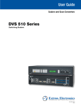
Application Diagram
The following application diagram shows an example in which four MGP 464W
processors are used with an Extron CrossPoint Ultra matrix switcher in a video wall
system.
TCP/IP
Network
TCP/IP
Network
TCP/IP
Network
TCP/IP
Network
TCP/IP
Network
TCP/IP
Network
MGP 464W MGP 464W
MGP 464W
CrossPoint
Ultra
Matrix Switcher
MGP 464W
RGBHV
RGBHV
RGBHV
RGBHV
RGBHV
RGBHV
RGBHV
YUV
YUV
Y/C
YUV
RGBHV
RGBHV
RGBHV
RGBHV
DVIDVI
DVI Bkgd
DVI Bkgd
DVI Bkgd
DVI Bkgd
DVIDVI
RGBHV
Image 1
Image 2
Image 3
Image 4
Image 5
WindoWall™ System
Scalable Multi-Graphic
Videowall Processor System
CROSSPOINT ULTRA SERIES
ULTRA-WIDEBAND MATRIX SWITCHER WITH ADSP™
Connection diagram for MGP 464W

PRELIMINARY
MGP 464W WindoWall Processor
2
Chapter Two
Installation and Operation
Installation Overview
Mounting the MGP 464W
Rear Panel Features
Front Panel
Resetting

MGP 464W • Installation and Operation
2-2
Installation and Operation
PRELIMINARY
Installation Overview
To install and set up multiple MGP 464W processor units for a video wall, follow
the steps below. (The WindoWall Console software can control up to 16 MGPs in a
video wall application.) See the application diagram in chapter 1, “Introduction,”
for a connection example.
1
Disconnect power from the MGPs, and turn off all other devices that will be
connected.
2
If desired, mount the MGPs. (See “Mounting the MGP 464W,” in the next
section.)
3
Attach all video sources to the input connectors of a matrix switcher such as
the Extron CrossPoint 450 Plus.
4
If using DVI inputs with the MGP 464W DI, connect each DVI input source to
a DVI distribution amplifier (DA), such as the Extron DVI DA 4.
5
Connect the matrix switcher’s video outputs to the MGP’s four sets of BNC
input connectors.
6
If using DVI inputs, attach each DA to one of the MGP 464W DI’s input
connectors.
7
Connect the video wall displays to the MGPs’ RGBHV/YUV BNC output
connectors and/or to their DVI-I output connectors.
8
Connect an active LAN Ethernet cable to the RJ-45 port on the MGP rear panel
to establish a link to the network.
9
Power up the input and output devices, then connect power to the MGP.
10
Install and set up the WindoWall
™
Console software on your computer. (See
“Setting Up the WindoWall
™
Console Software” in chapter 3, “Software-based
Configuration and Control.”)
N
Step 10 can be performed without the inputs, switcher, or any other hardware
connected to the MGP.
Mounting the MGP 464W
Tabletop use
Four self-adhesive rubber feet are included with the MGP 464W. For tabletop use,
attach one foot to each corner of the bottom of the unit and place the unit in the
desired location.
Rack mounting
UL guidelines for rack mounting
The following Underwriters Laboratories (UL) guidelines pertain to the installation
of the MGP into a rack:
• Elevatedoperatingambienttemperature — If the equipment is installed in
a closed or multi-unit rack assembly, the operating ambient temperature of
the rack environment may be greater than room ambient. Therefore, consider
installing the equipment in an environment compatible with the maximum
ambient temperature (Tma) specified by the manufacturer.
• Reducedairow — Installation of the equipment in a rack should be such
that the amount of air flow required for safe operation of the equipment is not
compromised.

2-3
MGP 464W • Installation and Operation
PRELIMINARY
• Mechanicalloading — Mounting of the equipment in the rack should be such
that a hazardous condition is not created due to uneven mechanical loading.
• Circuitoverloading — Consideration should be given to the connection
of the equipment to the supply circuit and the effect that overloading
of the circuits might have on overcurrent protection and supply wiring.
Appropriate consideration of equipment nameplate ratings should be used
when addressing this concern.
• Reliableearthing(grounding) — Reliable earthing of rack-mounted
equipment should be maintained. Particular attention should be given to
supply connections other than direct connections to the branch circuit (e.g.,
use of power strips).
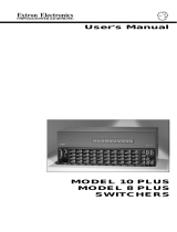
Rack mounting procedure
For optional rack mounting, do not install the rubber feet. To mount the
MGP 464W in a rack, follow these steps:
1. Attach the included mounting brackets (part #70-155-01) to the unit, using
eight of the machine screws supplied with the mounting kit. (See the
illustration below.)
2. Insert the unit into the rack, and align the holes in the mounting brackets with
the holes in the rack. Use four machine screws to attach the brackets to the
rack.
MBD 249
2U Rack Mounting
Bracket (Use four
lower holes.)
Rack mounting the MGP 464W

Installation and Operation, cont’d
MGP 464W • Installation and Operation
2-4
PRELIMINARY
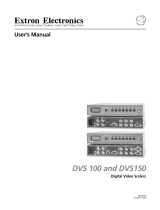
Rear Panel Features
The diagram below shows the rear panel of the MGP 464W DI, which has four
DVI-I connectors (
j
in the illustration below). The standard MGP 464W does
not have DVI capability, and therefore does not have these connectors. In all other
respects the MGP 464W and the MGP 464W DI rear panels are identical.
MGP 464W DI rear panel
a
Inputs 1, 2, 3, and 4 — Plug RGB, high or standard definition component
video, S-video, or composite video sources into these fully configurable BNC
connectors, as shown in the following diagram. These connectors can be
configured for the desired signal types via the WindoWall Console software.
RGBHV
Video
RGsB or
Component
Video
S-Video Composite
Video
RGBS or
RGBcvS
Video
H/HV
V
R/R-Y
G/Y
VID
B/C
B-Y
H/HV
B/C
B-Y
H/HV
V
R/R-Y
G/Y
VID
B/C
B-Y
V
R/R-Y
G/Y
VID
B/C
B-Y
H/HV
V
R/R-Y
G/Y
VID
B/C
B-Y
H/HV
V
R/R-Y
G/Y
VID
11111
Connecting to RGB/HD/Video inputs 1 through 4
b
Virtual inputs — Not used
c
RS-232/422 connector — Plug a computer or other RS-232 or RS-422 host
device into this connector. Wire the connector as shown on the next page. See
chapter 3, “Software-based Configuration and Control,” for more information
on controlling the MGP 464W remotely.
The pin assignments for the 9-pin RS-232/422 connector
(shown at right) are shown in the tables on the next page.
N
The cables used to connect the RS-232/422 ports to a
computer or control system may need to be modified by
removing pins or cutting wires. If unneeded pins are
connected, the processor may cease functioning.
.5A MAX
100
-
240
50/60 Hz
1
INPUT 1-DVI-D
R
R-Y
G/Y
VID
H/HV
V
H/HV
B/C
B-Y
2
R
R-Y
G/Y
VID
H/HV
V
H/HV
B/C
B-Y
3
R
R-Y
G/Y
VID
H/HV
V
H/HV
B/C
B-Y
4
R
R-Y
G/Y
VID
H/HV
V
H/HV
B/C
B-Y
R/
R-Y
10 13 16 19
G/Y
B/
B-Y
H/
HV
V
INPUT 2-DVI-D INPUT 3-DVI-D INPUT 4-DVI-D
DVI-D BACKGROUND
INPUT
DVI-D OUTPUT
RGB/Y, R-Y, B-Y OUTPUT
RS-232/422
LAN
R
VIRTUAL VIDEO INPUTSRGB VIDEO INPUTS
7
8
10
11
4
5
VID
Y
6
VID
B-Y
C
7
VID
R-Y
8
VID
Y
9
VID
B-Y
C
VID
R-Y
11
VID
Y
12
VID
B-Y
C
VID
R-Y
14
VID
Y
15
VID
B-Y
C
VID
R-Y
17
VID
Y
18
VID
B-Y
C
VID
R-Y
9
5
6
1
3
2
5 1
96

2-5
MGP 464W • Installation and Operation
PRELIMINARY
Pin RS-232 function Description
1 – No connection
2 Tx Transmit data
3 Rx Receive data
4 – No connection
5 Gnd Signal ground
6 – No connection
7 – No connection
8 – No connection
9 – No connection
Pin RS-422 function Description
1 – No connection
2 Tx- Transmit ground
3 Rx- Receive ground
4 – No connection
5 Gnd Signal ground
6 – No connection
7 Rx+ Receive data
8 Tx+ Transmit data
9 – No connection
d
LAN connector — To use the WindoWall software to
configure and control the MGP 464W, plug an RJ-45
network cable into this connector to connect the unit to
a network (via a switch, hub, or router) or to a single
computer.
ActivityLED— This yellow LED blinks to indicate
network activity.
LinkLED— This green LED lights to indicate a good
network connection.
Use a straight-through cable to connect to a network, or a crossover cable to
connect directly to a computer.
• For 10BaseT (10 Mbps) networks, use a Cat 3 or better cable.
• For100BaseT(max.155Mbps)networks,useaCat5cable.
Clip Down View
12345678
12345678
RJ-45
Connector
Insert
Twisted
Pair Wires
Pins:
Side View
Straight-through Cable
(for connection to a switch, hub, or router)
End 1 End 2
Pin Wire Color Pin Wire Color
1 white-orange 1 white-orange
2 orange 2 orange
3 white-green 3 white-green
4 blue 4 blue
5 white-blue 5 white-blue
6 green 6 green
7 white-brown 7 white-brown
8 brown 8 brown
Crossover Cable
(for direct connection to a PC)
End 1 End 2
Pin Wire Color Pin Wire Color
1 white-orange 1 white-green
2 orange 2 green
3 white-green 3 white-orange
4 blue 4 blue
5 white-blue 5 white-blue
6 green 6 orange
7 white-brown 7 white-brown
8 brown 8 brown
Wiring the LAN port
You will also need to configure the LAN port before using it. This is done by
using SIS commands. See “Command/response table for SIS commands” in
chapter 3, “Software-based Configuration and Control,” for details.
LAN
RJ-45
Port
Link
LED
Activity
LED

Installation and Operation, cont’d
MGP 464W • Installation and Operation
2-6
PRELIMINARY
The LAN port defaults are:
IP address: 192.168.254.254•
Gateway IP address: 0.0.0.0•
Subnet mask: 255.255.0.0•
DHCP: off•
e
Reset button — Pressing this recessed button causes various IP functions and
Ethernet connection settings to be reset to the factory defaults.
f
ResetLED— This green LED, located to the upper-right of the reset button,
blinks a varying number of times to indicate which reset mode has been
entered. See “Resetting,” later in this chapter, for details.
g
BNC output connectors — Plug an output device into this 5-BNC connector,
as shown below.
R
/R-Y
G
/Y
B
/B-Y
H
/HV
V
R
/R-Y
G
/Y
B
/B-Y
H
/HV
V
R
/R-Y
G
/Y
B
/B-Y
H
/HV
V
R
/R-Y
G
/Y
B
/B-Y
H
/HV
V
RGBHV RGBS
RGsB HD YUV Component Video
Connecting to output BNC connectors
h
DVI output — Plug a DVI output device into this DVI-I connector.
N
Analog RGB is not available on the DVI-I connector.
N
When two output devices are attached (one to each output connector), they both
display the same image.)
i
DVI background input — Connect a DVI input source to this DVI-I connector
in order to display the DVI video source live as a background on your output
screen. The four MGP windows are displayed in front of this DVI image.
When a DVI background is used, the MGP output is locked to the input rate
of the DVI background. This input is not scaled.
N
This input connector can be used only to receive the background image. The
input is not scaled or processed. To process DVI input signals, you must use the
MGP 464W DI model.
j
DVIinputs1,2,3,and4(MGP464WDIonly) — Connect up to four DVI
input sources to these DVI-I input connectors. These inputs are available only
on the MGP 464W DI model.
N
If the DVI source will be displayed on multiple cubes, the DVI signal must be
distributed to all MGPs.
k
AC power connector — Plug the power cord provided with the MGP into this
connector to connect the MGP to a 100–250 VAC, 50/60 Hz power source.

2-7
MGP 464W • Installation and Operation
PRELIMINARY
Front Panel
MGP 464
MULTI-GRAPHIC PROCESSOR
1
MGP 464W front panel
a
IndicatorLED — This green LED lights while the MGP is receiving power.
Resetting
Resetting the unit causes various IP functions and Ethernet connection settings to
revert to factory defaults. There are four reset modes (numbered 1, 3, 4, and 5 for
the sake of comparison with Extron IP Link products) that are available by pressing
the Reset button on the rear panel. The Reset button is recessed, so you must use
a pointed stylus, ballpoint pen, or Extron Tweeker to press it. See the table on the
next page for a summary of the reset modes.
C
Review the reset modes carefully. Using the wrong reset mode may result
in unintended loss of flash memory programming, port reassignment, or
processor reboot.
N
These resets close all open IP and Telnet connections and all sockets. Each mode
is a separate function, not a continuation/progression from mode 1 to mode 5.

Installation and Operation, cont’d
MGP 464W • Installation and Operation
2-8
PRELIMINARY
Reset Mode Comparison/Summary
Mode
Activation Result Purpose/Notes
1 Hold in the recessed
Reset button (located
next to the LAN
connector) while
applying power to the
unit.
3 Hold in the Reset button
for 3 seconds, until the
Reset LED blinks once.
Then, within 1 second,
press Reset again briefly
(for less than 1 second).
4 Hold in the Reset button
for 6 seconds, until the
Reset LED has blinked
twice: once at 3 seconds
and once at 6 seconds.
Then, within 1 second,
press Reset briefly (for
less than 1 second).
5 Hold in the Reset button
for 9 seconds, until the
Reset LED has blinked
three times: once at
3 seconds, once at
6 seconds, and once at
9 seconds. Then, within
1 second, press Reset
briefly (for less than 1
second).
Mode 1 causes the MGP to revert to the
factory default firmware. Event
scripting does not start if the unit is
powered on in this mode. All user files
and settings (drivers, audio adjustments,
IP settings, etc.) are maintained.
Mode 3 turns events on or off. During
resetting, the Reset LED flashes 2 times if
events are starting; 3 times if events are
stopping.
Mode 4 does the following:
• Enables ARP capability.
• Sets the IP address back to factory
default.
• Sets the subnet back to factory default.
• Sets the default gateway address back
to the factory default.
• Sets port mapping back to factory
default.
• Turns DHCP off.
• Turns all events off.
The Reset LED flashes 4 times in quick
succession during reset.
Mode 5 performs a complete reset to
factory defaults (except the firmware).
• Does everything mode 4 does.
• Resets everything that was set via the
Real Time Adjustments part of the
control program: all video settings and
miscellaneous options.
• Resets all IP options.
• Removes/clears all files from the
processor.
The Reset LED flashes 4 times in quick
succession during the reset.
Use mode 1 to
remove a version of
firmware if
incompatibility
issues arise.
Events must be
turned on if you
want to change IP
settings or
scheduling.
Mode 4 enables you
to set IP address
information using
ARP and the MAC
address.
Mode 5 is useful if
you want to start
over with control
software
configuration and
uploading, and to
replace events.

PRELIMINARY
MGP 464W WindoWall Processor
3
Chapter Three
Software-based Configuration
and Control
Setting Up the WindoWall
™
Console Software
Setting Up RS-232/422 Communication
Using Simple Instruction Set (SIS) Commands

MGP 464W • Software-based Conguration and Control
3-2
Software-based Configuration and Control
PRELIMINARY
Setting Up the WindoWall
™
Console Software
The WindoWall Console application software is the user interface to the
WindoWall system. It brings all the MGP 464W processors together via TCP/IP and
enables you to set up, create, and manage your video wall system. The software
includes wizards that take you through step-by-step procedures to configure the
input sources and the matrix switcher for the video wall. After completing the
setup, you can create additional customized window layouts using the virtual
canvas provided by the software, and save these layouts to up to 100 memory
presets for future recall.
N
Some configuration and control procedures can also be performed via
the MGP 464/MGP 464W Web pages. See chapter 4, “Ethernet-based
Configuration and Control,” for information on using the Web pages.
Installing and starting the software
You can complete the following startup procedure on the MGP either before or after
you connect the other hardware (inputs, outputs, and switcher) to it.
1. Insert the provided CD ROM into your computer's CD drive. The disk should
start automatically. If it does not, locate the LAUNCH.EXE file name on the
CD drive and double-click on it. The Extron Software Products screen opens.
N
If the WindoWall software does not appear on the CD provided with your MGP,
download it from the Extron Web site. See “Downloading the WindoWall
Console program from the Web,” later in this chapter.
Link to the installation software on the MGP 464W CD
/