Page is loading ...

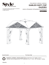
ITEM #0510327
12 FT × 10 FT GAZEBO
MODEL #TPGAZ17-002
ATTACH
YOUR RECEIPT HERE
Serial Number
___________
Purchase Date
___________
1
Questions, problems, missing parts? Before returning to your retailer, call our customer
service department at 1-866-439-9800, 8 a.m. - 8 p.m., ES T, Monday - Friday.
welcoming · sophisticated · inspiring
allen + roth is a registered trademark
of LF, LLC. All Rights Reserved.
AB17739
Espanol p. 12

DESCRIPTION
2
P
D
Q
E
F
G
H
N
O
R
A
C
B
T
S
M
L
K
I
J
PACKAGE CONTENTS
TRAPTRAP
Supporting Post
Post Bottom Plate
Post Plate Cover
Long Left Crossbar
Long Right Crossbar
Short Left Crossbar
Short Right Crossbar
Roof Connector
Hook
Long Top Connector Pole
Small Connector Pole
A
B
C
D
E
F
G
H
I
J
K
4
4
4
2
2
2
2
1
1
4
4
Short Top Pole
Short Top Pole
Small Top Connector
Small Top Beam
Finial
Air Vent Cover
Fabric Cover
Mosquito Net
Curtain
2
2
1
4
1
1
1
4
4
TRAPTRAP
NOITPIRCSEDNOITPIRCSED
YTITNAUQYTITNAUQ
L
M
N
O
P
Q
R
S
T
D

3
M6 × 30 mm Bolt
Qty. 16 + 2 Extra
M6 × 45 mm Bolt
Qty. 4 + 1 Extra
Washer
Qty. 32 + 4 Extra
Nut
Qty. 4 + 1 Extra
Cap
Qty. 28 + 3 Extra
Bolt Cover
Qty. 4 + 1 Extra
Wrench
Qty. 2
(NOT TO SCALE)
M6 × 15 mm Bolt
Qty. 8 + 1 Extra
Touch-up Paint
Qty. 1
AA CC
BB
DD EE
GG HHFF II
JJ
Stake
Qty. 16
(NOT TO SCALE)
HARDWARE CONTENTS (shown actual size)

4
AA
DD
FF
Washer
Cap
HH
Wrench
KEEP ALL FLAME AND HEAT AWAY FROM THIS TENT FABRIC.
Please read and understand this entire manual before attempting to assemble or install the product.
Two to four people are need for assembly.
Maximum load for the roof hook: 50 lbs.
x 8
x 2
x 8
x 8
SAFETY INFORMATION
WARNING:
CAUTION
PREPARTION
INSTALLATION INSTRUCTIONS
Hardware Used
This tent meets the flammability requirements of CPAI-84. The fabric may burn if left in continuous
contact with any flame source. The application of any foreign substance to the tent fabric may
render the flame-resistant properties ineffective.
Do not leave outside during high winds, heavy rains or snow. If high winds, heavy rains or snow
occurs, remove canopy and mosquito net, clear snow load from roof tube, and check for damage
before continued use.
Before beginning assembly of product, make sure all parts are present. Compare parts with package
contents list and hardware contents list. If any part is missing or damaged, do not attempt to assemble
the product.
Estimated Assembly Time: 2-3 hours
Tools Required for Assembly (not included): Ladder
Tools Required for Assembly (included): Wrench
1. Insert the post plate cover (C) into the supporting
post (A). Fit the post bottom plate (B) underneath
the supporting post (A). Insert two M6 x 15 mm bolts
(AA) into the washers (DD), supporting post (A) and
secure to the post bottom plate (B) using the
wrench (HH), but do not overtighten. Place caps
(FF) on the bolt heads. Slide the post plate cover
(C) down into place.
Repeat this step for the remaining supporting posts
(A), post bottom plates (B) and post plate covers (C).
M6 x 15 mm Bolt
1
FF
B
C
A
C
A
A
C
C
B
B
AA
AA
DD
DD
FF
FF

5
2
M6 × 45 mm Bolt
Washer
Nut
Cap
Bolt Cover
Bolt Cover
CC
DD
EE
FF
GG
HH
HH
M6 × 45 mm Bolt
Washer
Nut
Cap
CC
DD
EE
FF
GG
E
CC
DD
EE
D
DD
CC
EE
FF GG
Wrench
Wrench
INSTALLATION INSTRUCTIONS
Insert long right crossbar (E) into long left
crossbar (D). Secure together using
M6 x 45 mm bolt (CC), washers (DD) and
nut (EE). Tighten securely with the wrench
(HH). Place cap (FF) on the bolt head and
place bolt cover (GG) on the nut (EE).
Repeat the procedure for the other long right
crossbar (E) and long left crossbar (D).
Hardware Used
Hardware Used
3. Insert short right crossbar (G) into short left
crossbar (F). Secure together using
M6 x 45 mm bolt (CC), washers (DD) and
nut (EE). Tighten securely with the wrench
(HH). Place cap (FF) on the bolt head and
place bolt cover (GG) on the nut (EE).
Repeat the procedure for the other short right
crossbar (G) and short left crossbar (F).
2.
2
3
E
D
CC
DD
GG
E
D
FF
GG
E
D
G
F
G
F
CC
DD
EE
G
F
FF
GG
E
E
D
D
D
E
CC
DD
DD
EE
FF
GG
G
G
G
F
F
F
CC
DD
DD
EE
FF
GG

6
M6
×
30 mm Bolt
Washer
Cap
BB
DD
FF
5. Insert each small connector pole (K) into each
long top connector pole (J).
6. Screw the hook (I) into the roof connector (H)
and twist counterclockwise to tighten.
E
HH Wrench
INSTALLATION INSTRUCTIONS
Hardware Used
4. Secure the crossbar assemblies to the
supporting posts (A) using M6 x 30 mm
bolts (BB) and washers (DD). Tighten
securely with the wrench (HH). Place caps
(FF) on the bolt heads.
Note: Ensure the crossbar assemblies are
installed in the correct positions.The side with
curtain/netting hooks of the crossbar should
keep toward inside.
5
6
4
A
D
BB
DD
A
D
D
E
F
A
E
G
A
G
F
D
H
H
I
I
A
A
A
A
G
G
G
F
F
D
D
D
E
E
DD
BB
FF
J
J
A
A
A
A
D
D
G
F
F
G
E
E
DD
BB
J
J
K
K
H
I
I
H

INSTALLATION INSTRUCTIONS
7
L
7. Insert each long top connector pole (J) into
roof connector (H). Then insert each small
connector pole (K) into supporting posts (A).
8. Insert each short top pole (L) into opposite
ends of the roof connector (H), insert the
other end of short top pole (L) into the long
left crossbar (D). Insert each short top pole
(M) into opposite ends of the roof connector
(H), insert the other end of short top pole (M)
into the short left crossbar (F).
7
8
L
L
D
F
M
J
J
H
J
J
A
K
J
H
J
J
A
A
A
A
M
M
D
E
D
F
F
A
A
A
A
A
K
J
J
J
J
J
J
J
J
H
H
K
K
K
K
L
L
L
L
L
M
M
M
M
M
D
D
F
F
H
H
D
F

8
N
O
INSTALLATION INSTRUCTIONS
9. Insert each small top beam (O) into small
top connector (N). Attach the air vent cover
(Q) on the small top beam (O), then secure
with the finial (P).
10. Place the fabric cover (R) loosely on top of
the assembly. Insert each small top beam
(O) into the long top connector pole (J).
Note: Put each small top beam (O) loosely
on each long top connector pole (J) first,
then insert together, otherwise the last one
won’t insert correctly.
9
10
O
R
11
R
R
R
K
L
M
revo gnillup yb )R( revoc cirbaf eht nethgiT .11
the
four small connector poles as shown.
O
O
O
O
O
O
O
O
N
N
N
P
P
Q
Q
Q
Q
J

9
12.
13. Insert stakes (II) through the holes in the post
bottom plates (B) and into the ground to
secure the gazebo.
Note: This gazebo can be secured to the
deck (wood or concrete), but customers
need to prepare the appropriate hardware
(expansion bolts or sheet-metal screws ) for
fixing.
C
INSTALLATION INSTRUCTIONS
ATTENTION: Keep the curtain outside and
the mosquito net inside during assembly.
Close the zippers on the curtain and mosquito
net before hanging them. If they need to be
removed, make sure the zippers are closed
first.
Hang the mosquito net (S) and curtain (T) on
the crossbars using the hooks preassembled
on the crossbars. Note: Be mindful of the tag
hanging on the zipper of mosquito net (S) and
curtain (T). This tag indicates which side is 12
ft. and which side is 10 ft.
12
B
C
II
T
S
12
′-2
10 ′-1
10′-1
12′-
2
10′-3
10
′-3
12
′
-4
12′-4
12
′
′
10′
T
T
T
T
S
S
G
G
G
G
T
S

1. It is the manufacturer’s recommendation to
remove the canopy during high winds, heavy
rains or snow. To do so, simply reverse the
order of instructional steps 9-11 in ASSEMBLY
INSTRUCTIONS on page 8.
P
Q
R
Q
O
Q
P
10
INSTALLATION INSTRUCTIONS
Slight pinholes will be present in the tubing, which is customary of original steel work and should not
be considered.
Wash with soap and water.
Before storing, remove leaves and dirt, drain all water that may have accumulated in or around the
frame. If not
drained properly, water can cause freeze damage including bursting or cracking of
Repair any scratches to the frame using touch-up paint (JJ).
metal tubing.
CARE AND MAINTENANCE
1

This warranty is extended to the original purchaser and applies to defects in materials and
workmanship of your outdoor furniture or accessory item(s), provided it is maintained with care and
used only for personal, residential purposes.
Frames and welds are warranted to be free from defects in material or workmanship for a period of
one year.
Fabric is warranted for a period of one year against defects in material or workmanship.
This warranty is not transferable and does not cover products damaged by misuse, neglect,
accident, alterations
or use and maintenance other than that specified in this instruction.
The manufacturer will not be held liable for any direct, indirect, incidental or consequential damages.
Some states do not allow limitations on how an implied warranty lasts, or the exclusion or limitation
of incidental
or consequential damages, so the above limitations may not apply to you.
This warranty gives you specific legal rights, and you may also have other rights which vary from
state to state.
U. S. A. Customers: Replacement canopies are available for purchase at www.Lowes.com.
For replacement parts, call our customer service department at 1-866-439-9800, 8 a.m. - 8 p.m.,
EST, Monday - Friday.
Printed in China
11
AA CCBB
DD
EE
HH
PART DESCRIPTION PART#
AA
BB
CC
DD
EE
HH
M6 × 15 mm Bolt
M6 × 30 mm Bolt
M6 × 45 mm Bolt
Washer
Nut
Wrench
T51
T52
T53
T54
T55
T56
WARRANTY
REPLACEMENT PARTS LIST

ARTÍCULO #0510327
GAZEBO DE 3,65 M X 3,04 M
MODELO #TPGAZ17-002
ADJUNTE SU RECIBO AQUÍ
Número de serie
___________
Fecha de compra
___________
12
Preguntas, problemas, piezas faltantes? Antes de volver a la tienda, llame a nuestro
Departamento de Servicio al Cliente al 1-866-439-9800, de lunes a viernes de 8 a.m.
a 8 p.m., hora estándar del Este.
welcoming · sophisticated · inspiring

DESCRIPTION
13
CONTENIDO DEL PAQUETE
TRAPTRAP
Poste de apoyo
Placa inferior del poste
Cubierta de la placa del poste
Barra transversal izquierda
Barra transversal derecha larga
Barra transversal izquierda corta
Barra transversal derecha corta
Conector para techo
Gancho
Varilla conectora superior larga
Varilla conectora pequeña
A
B
C
D
E
F
G
H
I
J
K
4
4
4
2
2
2
2
1
1
4
4
Varilla superior corta
Conector superior pequeño
Cubierta para perno
Remate
Cubierta del respiradero
Cubierta de tela
Mosquitero
Pared lateral
2
2
1
4
1
1
1
4
4
AZEIPAZEIP
NÓICPIRCSEDNÓICPIRCSED
DADITNACDADITNAC
L
M
N
O
P
Q
R
S
T
larga
Varilla superior corta
P
D
Q
E
F
G
H
N
O
R
A
C
B
T
S
M
L
K
I
J
D

14
Perno M6 x 30
Cant. 16 + 2 adicional
Perno M6 x 45
Cant. 4+1 adicional
Arandela
Cant. 32 + 4 adicional
Tuerca
Cant. 4 + 1 adicional
Topa
Cant. 28 + 3 adicional
Cubierta para perno
Cant. 4 + 1 adicional
LIave
cant. 2
(NO ESTÁ A ESCALA)
Perno M6 x 15
Cant. 8 + 1 adicional
Pintura de
retoque
AA CC
BB
DD EE
GG HHFF II
JJ
Estaca
Cant. 16
(N
O ESTÁ A ESCALA
)
ADITAMENTOS (se muestran en tamaño real)
Cant. 1

15
AA
DD
FF
Arandela
Topa
HH
LIave
MANTENGA LA TELA DE LA TIENDA DE CAMPAÑA ALEJADA DE LAS LLAMAS Y DEL CALOR.
Lea y comprenda completamente este manual antes de intentar ensamblar o instalar el producto.
Para realizar el ensamblaje se necesitan de dos a cuatro personas.
Carga máxima pare el gancho del techo: 22, 67 kg
x 8
x 2
x 8
x 8
INFORMACIÓN DE SEGURIDAD
ADVERTENCLA:
PRECAUCIÓN
PREPARACIÓN
INSTRUCCIONES DE INSTALACIÓN
Aditamentos utilizados
Esta tienda de campaña cumple con los requisitos de inflamabilidad de la noria CPAI-84. La
tela podría arder si se encuentra en continuo contacto con cualquier fuente de calor. La aplicación
de cualquier sustancia extraña a la tela de la tienda de campaña puede hacer que sus
No lo deje afuera si hay vientos, lluvia o nieve fuerte. Si hay vientos, lluvia o nieve fuente, retire el
toldo y el toldo y el mosquitero, limpie la carga de nieve del tubo del techo y revise si hay daños
antes de continuar el uso.
Antes de comenzar a ensamblar el producto, aseqúrese de tener todas las piezas. Compare las
piezas con la lista del contenido del paquete y la lista de aditamentos. No intente ensamblar el
producto si falta alguna pieza o si estas están dañadas.
Tiempo estimado de ensamblaje: 2 a 3 horas
Herramientas necesarias para el ensamblaje (no se incluyen): escalera.
Herramientas necesarias para el ensamblaje (se incluyen): llave.
1. Inserte la cubierta de la placa del poste (C) en el
poste de apoyo (A). Calce la placa inferior del poste (B)
bajo el poste de apoyo (A). Inserte dos pernos M6 x 15
(AA) en la arandela (DD) el poste de apoyo (A) y
asegure a la placa inferior del poste (B) utilizando la
llave, pero sin apretar demasiado. Coloque la tapa
(FF) en la cabeza del perno. Deslice la cubierta de la
placa del poste (C) hasta su lugar.
Repita este paso los postes de apoyo (A), las placas
inferiores del poste (B) y las cubiertas de la placa del
poste (C) restantes.
Perno M6 x 15
propiedades ignífugas se anulen.
1
FF
B
C
A
C
A
A
C
C
B
B
AA
AA
DD
DD
FF
FF

16
Perno M6 x 45
Arandela
Tuerca
Topa
Cubierta para perno
Cubierta para perno
CC
DD
EE
FF
GG
HH
HH
Perno M6 x 45
Arandela
Tuerca
Topa
CC
DD
EE
FF
GG
E
CC
DD
EE
D
DD
FF
LIave
LIave
INSTRUCCIONES DE INSTALACIÓN
Inserte la barra transversal derecha larga (E) en
la barra transversal izquierda larga (D).
Asegure y únalas usando pernos M6 x 45 (CC)
y tuercas para pernos (DD). Apriete firmemente
con la llave hexagonal (EE) y la llave (FF).
Coloque la tapa (FF) en la cabeza del perno y
coloque la cubierta para pernos (GG) en la
tuerca (EE).
Repita el procedimiento con la otra barra
transversal derecha large (E) y la barra
transversal izquierda larga (D).
Aditamentos utilizados
Aditamentos utilizados
3. Inserte la barra transversal derecha corta (G) en
la barra transversal izquierda corta (F). Asegure
y únalas usando pernos M6 x 45 (CC), arandelas
(DD) y tuercas (EE). Apriete firmemente con la
llave (HH). Coloque la tapa (FF) en la cabeza del
perno y coloque la cubierta para pernos (GG) en
Repita el procedimiento con la otra barra
transversal derecha corta (G) y la barra
transversal izquierda corta (F).
2.
la tuerca (EE).
2
E
CC
DD
EE
D
DD
CC
EE
FF GG
2
3
E
D
CC
DD
GG
E
D
FF
GG
E
D
G
F
G
F
CC
DD
EE
G
F
FF
GG
E
E
D
D
D
E
CC
DD
DD
EE
FF
GG
G
G
G
F
F
F
CC
DD
DD
EE
FF
GG

17
Perno M6 x 30
Arandela
Topa
BB
DD
FF
5.
Inserte cada varilla conectora pequeña (K) en
cada varilla conectora superior larla (J).
6.
HH
Liave
INSTRUCCIONES DE INSTALACIÓN
Aditamentos utilizados
4. Asegure los ensambles de las barras
transversales a los postes de apoyo (A) con
pernos M6 x 30 (BB) y las arandelas (DD).
Apriete firmemente con la llave (EE). Coloque
la tapa (FF) en la cabeza del perno.
Nota: asegúrese de que los ensambles de las
barras transversales estén instalados en la
posición correcta. El lado con los ganchos para
cortina/red de la barra transversal debe
mantenerse hacia dentro.
Enrosque el gancho (I) en el conector del techo
(H) y gire en dirección contraria a las manecillas
del reloj para apretar.
E
5
6
4
A
D
BB
DD
A
D
D
E
F
A
E
G
A
G
F
D
H
H
I
I
A
A
A
A
G
G
G
F
F
D
D
D
E
E
DD
BB
FF
J
J
A
A
A
A
D
D
G
F
F
G
E
E
DD
BB
J
J
K
K
H
I
I
H

18
L
7
8
L
L
D
F
M
J
J
H
J
J
A
K
J
H
J
J
A
A
A
A
M
M
D
E
D
F
F
A
A
A
A
A
K
J
J
J
J
J
J
J
J
H
H
K
K
K
K
L
L
L
L
L
M
M
M
M
M
D
D
F
F
H
H
D
F
INSTRUCCIONES DE INSTALACIÓN
7. Inserte cada varilla conectora superior larga (J)
en del conector del techo (H). Luego, inserte
cada varilla conectora pequeña (K) en los
postes de apoyo (A).
8. Inserte cada varilla superior corta (L) en los
extrenos opuestos del conector del techo (H),
inserte el otro extremo de la varilla superior
corta (L) en la barra transversal izquierda larga
(D). Inserte cada varilla superior corta (M) en
los extrenos opuestos del conector del techo
(H), inserte el otro extremo de la varilla superior
corta (M) en la barra transversal izquierda
corta (F).

19
Apriete la cubierta de tela (R) jalándola sobre
las cuatro varillas conectora pequeña, como se
muestra.
11.
11
R
R
R
K
L
M
N
O
9
10
O
R
O
O
O
O
O
O
O
O
N
N
N
P
P
Q
Q
Q
Q
J
INSTRUCCIONES DE INSTALACIÓN
9. Inserte cada viga superior pequeña (O) en la
conector superior pequeño (N). Fije la cubierta
del respiradero (Q) en la viga superior pequeña
(O), luego asegure el remate (P).
10. Coloque la cubierta de la tela (R) de forma
suelta en la parte superior del ersamble.
Inserte cada viga superior pequeña (O) en
la varilla conectora superior larga (J).
Nota: coloque cada viga superior pequeña
(O) sin apretar en cada varilla conectora
superior larga (J) primero, luego inserte
juntos; de lo contrario, la última no se
insertará correctamente.

20
13.
INSTRUCCIONES DE INSTALACIÓN
ATENCIÓN: mantenga la pared lateral afuera
y el mosquitero dentro durante el
ensamblaje. Cierre las cremalleras en la
pared lateral y el mosquitero antes de
colgarlos. Si necesita retirarlos, asegúrese
primero de que las cremalleras estén
cerradas.
12.
Cuelgue el mosquitero (S) y la pared lateral (T)
en las barras transversales usando los
ganchos adjuntos en las barras transversales.
Preste atención a la etiqueta que cuelga del
cierre del mosquitero (S) y la pared lateral (T).
Esta etiqueta indica qué lado es de 3,65 m y
qué lado es de 3,04 m.
Nota: este gazebo se puede fijar a la terraza
(madera o concreto), pero los clientes deben
preparar los aditamentos adecuados (pernos
de expansión o tornillos para láminas de metal)
para fijar.
Pase las estacas (II) por los orificios en las
placas inferiores de los postes (B) y en el suelo
para asegurar el gazebo.
C
12
B
C
II
T
T
T
T
S
S
G
G
G
G
12
′-2
10 ′-1
10′-1
12′-
2
10′-3
10
′
-3
12
′-4
12′-4
12
′
′
10′
T
S
/