Gossen MetraWatt SmartControl Operating instructions
- Type
- Operating instructions

Mounting Instructions
SMARTCONTROL | ECS 3-349-770-03
Energy Management-System 4/5.19

Mounting Instructions
2 GMC-I Messtechnik GmbH
1 Range of Applications
Diverse Data Collector and Data Messenger
The SMARTCONTROL renders energy consumption measurable without delay in a detailed fashion,
and thus controllable. This, in turn, is the basic prerequisite for a great variety of measures for
the reduction of energy consumption and costs, for example with regard to:
- Optimized utilization
- Contracting
- Component modernization
- Conversion
The SMARTCONTROL is an inexpensive, user-friendly, easy to integrate data logging system.
This is the prerequisite for quickly establishing efficient, sustainable, widespread energy
management for buildings and properties.
Amongst other data, the SMARTCONTROL is capable of recording the following:
- Meter readings (electrical power, heat, water, gas etc.)
- Temperatures (inside, outside, inlet, return etc.)
- Statuses (burner and pump on-times etc.)
- Analog signals from external signal converters and measuring transducers (pressure,
humidity etc.)
- M-Bus protocol (up to 450 meters), ModBus, SBus, CLBus, LON
One of the system’s important advantages is its ability to access all relevant data at any time –
quickly and conveniently.
We’re at your disposal and can provide you with solutions if you want to make actual energy
consumption more transparent in the future, and optimize it as well.
Information regarding all facets of GMC-I Messtechnik GmbH, as well as other industry information,
can be accessed at:
GMC-I Messtechnik GmbH
Südwestpark 15
90449 Nürnberg, Germany
Phone: +49 (0) 911 8602-111
Fax: +49 (0) 911 8602-777
e-mail: info@gossenmetrawatt.com
Internet: www.gossenmetrawatt.com

Mounting Instructions
GMC-I Messtechnik GmbH 3
1. Mounting
1.1. Before Mounting
Note:
Please check to make sure that the SMARTCONTROL and all included accessories are complete and
undamaged. The freight forwarder must be notified without delay in the event of transport
damage. The device may not be placed into operation in the event of damage.
Observe all instructions in the SMARTCONTROL manual as well!
1.1.1. Scope of Delivery for SMARTCONTROL Standard
The following is included in scope of delivery:
SMARTCONTROL
User’s manual
Installation report
These mounting instructions
CD with SMARTCONTROL software and documentation
RJ-45 crossover patch cable for connecting the SMARTCONTROL to a PC
Mounting materials:
o 3 x 6 mm anchors
o 3 wooden screws (1 countersunk head / 2 flat head)
o 5 cable ties
o 1 mounting aid
o 1 Screwdriver
The PC can also be connected by means of an additional module via analog modem, ISDN, GSM or Bluetooth.
Further information is included in the SMARTCONTROL manual.
1.1.2. Scope of Delivery for SMARTCONTROL IP-65
The SMARTCONTROL is delivered in a control cabinet which fulfills IP 65 requirements (optionally lockable, lock
meets IP 34). The SMARTCONTROL consists of a single PCB system, a power pack, a circuit breaker and various
attachable components. In addition to this, optional devices (e.g. M-Bus, fieldbus) can be secured to the
integrated mounting rail or inserted into available slots on the PCB (e.g. socket modules or memory expansions).
The metric fittings (2 ea. M20, 3 ea. M16) are attached to the flange plate for the cable entry.
1.2. Operating Conditions
Tip:
Carefully select the location at which the SMARTCONTROL will be installed. Don’t forget that a
230 V AC mains connection is required for operation of the SMARTCONTROL and, if applicable, that
communication facilities must be provided for remote read-out, for example via ISDN.
Recommended installation height: at least 50 cm, and not more than 150 cm from the floor to the bottom
edge of the cabinet or housing. The wall to which the device is mounted must be flat, dry and sturdy.
Furthermore, the location of sensors, transducers and other devices which will be connected to the
SMARTCONTROL must also be taken into consideration in order to minimize wiring expenses.

Mounting Instructions
4 GMC-I Messtechnik GmbH
Note:
Close proximity to water, sources of heat, direct sunlight, radiators, devices which generate
electromagnetic fields, transmitters, high frequency sources, radiation emitting devices and
locations which are exposed to excessive vibration or shock must be avoided.
Ambient temperature should lie within a range of +5 to +50 °C, and no condensation is allowed. If
these requirements are not fulfilled by prevailing ambient conditions, pleased install fully
encapsulated devices only.
When recording energy data, make sure that the SMARTCONTROL is protected against
manipulation and destruction.
The devices are not intended for use in explosion-proof zones.
Observe additional information included in section 3 of the SMARTCONTROL Installation Instructions, “General
Safety Precautions”, as well as further information and instructions in the SMARTCONTROL manual.
1.3. Wall Mounting
Warning:
Before drilling holes, make sure that there are no cables, pipes or other lines
which have been laid inside the wall in close proximity to the intended
installation position.
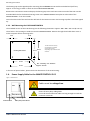
1.3.1. Wall Mounting the SMARTCONTROL Standard
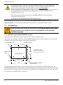
The housing has the following dimensions: approx. 226 x 210 x 70 mm (W x H x D).
The 3 holes in the housing are used to mount the SMARTCONTROL. Remove the 2 housing screws at the bottom
and open the housing cover in order to expose the mounting holes.
The top mounting hole is laid out as a slot, and the thickness of the housing wall is approximately 1 mm. The
SMARTCONTROL Standard is shipped with 4 installed housing screws. Only the two screws at the bottom need to
be loosened for mounting, because the opening in the housing top is only intended for the fiber-optic cable. The
top screws may not be loosened for this reason.
22.6 cm
16 cm
21 cm
The box must be securely
mounted with 3 suitable
screws and anchors, depending
upon substrate and material.
Housing Rear Panel
11.3 cm
11.3 cm
16 cm
Box mounting tab diameter:
approx. 5 mm
3.3 cm
3.3 cm
2.6 cm
Top Housing Screw
Top Housing Screw
Bottom Housing
Screw

Mounting Instructions
GMC-I Messtechnik GmbH 5
The housing top can be tipped up after removing the two bottom screws with the included tool (stiff wire,
approx. 25 cm long) in order to work on the installed SMARTCONTROL.
Remove the two bottom screws and tip up the housing top to this end. Now insert one end of the tool into the
threaded drill hole for the bottom housing screw in the SMARTCONTROL base plate at either side of the
SMARTCONTROL – from the outside.
Insert the other end of the tool into the drill hole for the bottom screw in the housing top after it has been tipped
up.
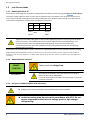
1.3.2. Wall Mounting the IP 65 SMARTCONTROL
The standard version of the IP 65 housing has the following dimensions: approx. 380 x 380 x 210 mm (W x H x D).
The 4 holes in the housing are used to mount the SMARTCONTROL. Remove the right-hand cable duct cover in
order to expose all four mounting holes.
In the case of special orders, please check the dimensions of the IP 65 housing.
1.4. Power Supply Cable for the SMARTCONTROL IP 65
Warning:
Cables must be voltage-free.
Note:
The cables must be lead in from the bottom and secured by
means of heavy-duty cable glands.
It must be assured that the cables are long enough to reach the
connector terminals.
38 cm
34 cm
34 cm
38 cm
The box must be securely
mounted with 4 suitable
screws and anchors,
depending upon substrate and
material.
Box mounting tab diameter:
approx. 8.2 mm
2 cm
2 cm
Housing Rear Panel
2 cm
2 cm
PCB
Figure 1: IP 65 Cabinet
Terminal Block
Heavy-Duty Cable Gland
Cable Duct
Ground Bus Bar

Mounting Instructions
6 GMC-I Messtechnik GmbH
SMART-
CONTROL
1.5. Low-Current Leads
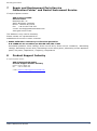
1.5.1. SMARTCONTROL IP 65
The leads are fed through the heavy-duty cable glands at the bottom of the housing (see Figure 1: IP 65 Cabinet).
The power supply cable may have no more than 3 conductors with a maximum cross-section of 4 square mm
each, and must be led in through the heavy-duty cable gland at the bottom of the housing. This cable must be
connected to the 230 V AC terminal block (see below): N, PE and L1.
PE
N
F1
L1
Green-
yellow
Blue
Brown-
black
Note:
Tighten the threaded cable glands to the specified tightening torque. The housing must be water-
proof. If necessary, the included connectors must be replaced with more suitable ones, and
unused connectors must be replaced with blanking plugs. It must be assured that only
standardized materials which are suitable for the IP 65 standard and which seal the openings
appropriately are utilized.
The shields of all shielded cables must be connected to a ground bus bar by means of shield terminals assuring
large surface-area connection. Identify all cables which are fed into the housing with the respective cable number in
accordance with the wiring diagram in a readily legible fashion using cable ties. Secure the cables firmly, with cable ties if
necessary.
1.5.2. SMARTCONTROL Standard
Warning:
Cables must be voltage-free.
Note:
The cables must be lead in from the bottom and secured by
means of heavy-duty cable glands.
It must be assured that the cables are long enough to reach the
connector terminals.
1.5.3. All Types of SMARTCONTROL After Mounting
Note:
► Retighten all screws and fasteners after installation has been completed.
Warning:
► Insulation testing must be executed in accordance with VDE. Do not
expose components which are not voltage-proof to high voltages
during testing.
Ground Bus Bar

Mounting Instructions
GMC-I Messtechnik GmbH 7
7 Repair and Replacement Parts Service
Calibration Center
*
and Rental Instrument Service
If required please contact:
GMC-I Service GmbH
Service Center
Beuthener Str. 41
90471 Nürnberg, Germany
Phone: +49 911 817718-0
Fax: +49 911 817718-253
e-mail: [email protected]om
www.gmci-service.com
This address is only valid in Germany.
Please contact our representatives or
subsidiaries for service in other countries.
* DAkkS Calibration Laboratory for Electrical Quantities
D-K-15080-01-01 accredited per DIN EN ISO/IEC 17025
Accredited quantities: direct voltage, direct current value, direct current- resistance, -alternating
voltage, alternating current value, alternating current active power, alternating current apparent
power, DC power, capacitance, -frequency, temperature
8 Product Support Industry
If required please contact:
GMC-I Messtechnik GmbH
Product Support Hotline Industry
Phone: +49 911 8602-500
Fax: +49 911 8602-340
e-mail: support.industrie@gossenmetrawatt.com

Mounting Instructions
8 GMC-I Messtechnik GmbH
Edited in Germany • Subject to change without notice • PDF version available on the Internet
Phone: +49 911 8602-111
GMC-I Messtechnik GmbH Fax: +49 911 8602-777
Südwestpark 15 e-mail: [email protected]
90449 Nürnberg, Germany www.gossenmetrawatt.com
-
 1
1
-
 2
2
-
 3
3
-
 4
4
-
 5
5
-
 6
6
-
 7
7
-
 8
8


Gossen MetraWatt SmartControl Operating instructions
- Type
- Operating instructions
Ask a question and I''ll find the answer in the document
Finding information in a document is now easier with AI
Related papers
-
Gossen MetraWatt SmartControl Installation guide
-
-
-
-
-
-
-
-
-
