Page is loading ...


3
Safety
Warning! Only a competent electrician may install the ACS 400V.
Warning! Dangerous voltages are present when mains supply is connected. Wait at least 5
minutes after disconnecting the supply before removing the cover. Measure the voltage
at DC terminals (U
c+
, U
c-
) before servicing the unit. See ACS 400 User’s Manual
Reference Section E.
Warning! Even when the motor is stopped there are dangerous voltages present at Power Circuit
terminals U1, V1, W1 and U2, V2, W2 and U
c+
, U
c-
.
Warning! Even when the ACS 400V is powered down, there may be dangerous external voltages
at relay terminals RO1A, RO1B, RO1C, RO2A, RO2B, RO2C.
Warning! Never attempt to repair a broken unit; contact the supplier.
Warning! The ACS 400V will start up automatically after an input voltage interruption if the
external run command is on.
Warning! When the control terminals of two or more ACS100/140/160/400/400V units are
connected in parallel, the auxiliary voltage for these control connections must be taken
from a single source which can either be one of the units or an external supply.
Warning! The heat sink may reach a high temperature (see ACS 400 User’s Manual Reference
Section S, Table 11).
Warning! The ACS 400V unit with a RFI filter cannot be used in distribution networks isolated
from earth (floating networks, IT networks). Otherwise the net will be connected with the
earth potential via filter capacitors.
If the drive is connected to IT network, grounding screws and the RFI filter must be removed. Refer to
ACS 400 User’s Manual Reference section I Floating Network for instructions on screw locations.
Note! For more technical information refer to ACS 400 User’s Manual or contact your local ABB
supplier.

4

5
This instruction is a supplement to the ACS 400 User’s Manual which is delivered with the frequency
converter. This instruction describes the unique features of ACS 400V which make it especially suitable
for HVAC (heating, ventilation and air conditioning) applications. The software of this product has been
developed in co-operation with Fläkt Woods Group. In case of other technical information, a reference
to the ACS 400 User’s Manual is made.
Table of Contents
Safety ..................................................................................................... 3
Installing the ACS 400V ........................................................................ 7
Controlling the ACS 400V ................................................................... 10
I/O Configuration ................................................................................. 11
Alternative ACS 400V Operation Modes (Hardwire Connections) .. 12
Start / Stop and External Control Signal 0-10 V ....................................................12
Start / Stop with 1 Constant Speed .......................................................................13
Start / Stop with 2 Constant Speeds .....................................................................14
PID Control with 1 Setpoint ...................................................................................15
PID Control with 2 Setpoints .................................................................................16
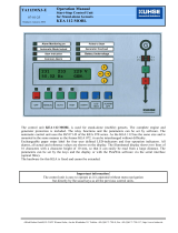
Operating with ACS-PAN-A Control Panel ........................................ 17
Control Modes .......................................................................................................17
Actual Values in Output Display ............................................................................18
Menu Structure .....................................................................................................18
Setting Parameter Value .......................................................................................18
Changing Between Basic and Full Parameter Set ................................................19
Diagnostic displays ...............................................................................................19
Resetting the Drive from the Control Panel ..........................................................19
LED Indicators ......................................................................................................19
Parameterising ACS 400V .................................................................. 20
Appendix 1: .......................................................................................... 22
Electro Magnetic Compatibility EMC .....................................................................22

6

7
Installing the ACS 400V
Mount the ACS 400V with the RFI filter on the wall. With ACS 400V for powers 15 kW and more (frame
size R3 and R4) the RFI filter can be mounted either below or next to the drive.
Figure 1 ACS 400V Frame sizes R1 and R2 (3.0 - 11 kW).
Drive Type
ACS401-
RFI Filter Type A (mm) B (mm) C (mm) D (mm) E (mm)
V004 - V006 ACS400-IF11-3 90 361.5 35 98 318
V009 - V011 ACS400-IF21-3 90 461 35 98 417


9
Connect the RFI filter to the supply (line) side of the drive. See ACS 400V and corresponding RFI filter
mounting dimensions from the table below.
Mount the IP54 protection cover(s) to the RFI filter end(s) to get IP54 protection class for the EMC filter.
The frequency converter unit protection class depends on the ordered type. In frame size R1 and R2
one IP54 filter cover is required on the supply cable entry end of the filter. In frame size R3 and R4 two
IP54 filter covers are required, one on each end. See the following figures for mounting and cabling.
Figure 3 Cabling ACS 400V with IP54 protection cover.
Control Cables
Supply Cable
Cable
Between
RFI Filter
and ACS 400V
Motor Cable
Note! ACS-CHK-C is needed and supplied only with ACS400-IF41-3 filter.

10
Controlling the ACS 400V
The ACS400V can be used from external or local control locations.
External control possibilities
1. Control from I/O: Depending on the I/O connections ACS 400V can be used in alternative operation
modes. These modes, which are explained later in more detail, are designed to meet the requirements
of several HVAC applications:
• Speed Control via External Control Signal 0-10 V, see page 12
• Start / Stop with 1 Constant Speed, see page 13
• Start / Stop with 2 Constant Speeds, see page 14
• PID Control with 1 Setpoint, see page 15
• PID Control with 2 Setpoints, see page 16
2. Control via Fieldbus: Modbus protocol is as default fieldbus in ACS 400V. In order to use other
fieldbuses an external fieldbus module and an ACS 400 DDCS adapter must be used, both are
available as options. N2 fieldbus is also available as embedded fieldbus option for ACS 400V.
Local control possibilities
1. Control from control panel: ACS 400V can be directly controlled from control panel without making
any connections to the ACS 400V I/O. In this case motor starts and stops from control panel’s START/
STOP button and required speed (Hz) is set with control panel.
2. Control with PC-tool DriveWindow Light: For set-up and control purposes the PC-tool DriveWindow
Light is also available as an option. For using this tool ACS 400V has to be equipped with an optional
ACS 140 RS 485/232 adapter.
Contact your local ABB supplier for more information on options.
Figure 4 ACS 400V control locations.
X2 Panel Port “Modified RS232”
ACS 140 RS485/232
RS-232
DriveWindow Light
Local control
External control
Control Panel ACS-PAN-A
X3
Modbus fieldbus
I/O
X1
Optional
DDCS
Module
Optional fieldbus

11
I/O Configuration
The following diagram summarizes the I/O connection alternatives given by the ACS 400V.
Figure 5 ACS 400V I/O connection.
Input signals Output signals
DIP switches, set to
voltage signal positions
• Start/stop (DI1) • Analogue output AO: Frequency
0 - 50 Hz <=> 0- 20 mA
• Control signal 0 - 10 V(AI1) • Relay output 1: Fault
-> 17 connected to 18
• Actual value 0 - 10 V, eg. from
pressure sensor (AI2)
• Relay output 2: Running
-> 20 connected to 22
• Activate to select PID control
(DI2)
• Select setpoint1/setpoint2 (DI3)
• Constant speed 1 (DI4)
• Constant speed 2 (DI5)
ON ON
AI1: 0 - 10 V
AI2: 0 - 10 V
1
2
3
4
5
6
7
8
9
10
11
12
13
14
15
16
17
18
19
20
21
22
SCR
AI1
AGND
+10V
AI2
AGND
AO1
AGND
+24V
DCOM1
DI1
DI2
DI3
DI4
DI5
DCOM2
RO1C
RO1A
RO1B
RO2C
RO2A
RO2B
2
1
3
4
5
6
7
8
9
10
11
12
13
14
15
16
17
18
19
20
21
22
SCR
AI1
AGND
+10V
AI2
AGND
AO1
AGND
+24V
DCOM1
DI1
DI2
DI3
DI4
DI5
DCOM2
RO1C
RO1A
RO1B
RO2C
RO2A
RO2B
X1 X1
+24V
DI configuration PNP
connected (source)
with external
power supply
DI configuration
NPN connected
(sink)
±0V

12
Alternative ACS 400V Operation Modes (Hardwire Connections)
Start / Stop and External Control Signal 0-10 V
• Set DIP switches to voltage signal positions
• Start signal is given by activating DI1 (11)
• Control signal 0-10 VDC from external regulator is connected to AI1 (2, 3)
• Two constant speeds are possible, if 8, 14 and 8, 15 are connected using a switch between 14 and
15, see page 14
1
2
3
4
5
6
7
8
9
10
11
12
13
14
15
16
17
18
19
20
21
22
SCR
AI1
AGND
+10V
AI2
AGND
AO1
AGND
+24V
DCOM1
DI1
DI2
DI3
DI4
DI5
DCOM2
RO1C
RO1A
RO1B
RO2C
RO2B
(
Start/Stop
External control signal 0-10V
Screen control signal cable
+ Pressure sensor 0 - 10V
Output frq 0 - 50Hz <=> 0 - 20mA
Start / Stop
Activate PID control
Select setpoint1 / setpoint2
Constant speed 1
Constant speed 2
Fault = 17-19
breaks
Running =
20 connected to 22
RO2A
+ Control signal 0 - 10V
X1
+ Reference voltage 10 VDC
+ Auxiliary voltage 24 VDC
AI1: 0- 10 V
AI2: 0- 10 V
ON ON
-
-
DIP switches

13
Start / Stop with 1 Constant Speed
• Set DIP switches to voltage signal positions
• Motor starts by activating DI1 (11)
• One constant speed can be set
• Constant speed 1 is set with parameter 1202
• Constant speed 1 is selected with DI4 (14)
1
2
3
4
5
6
7
8
9
10
11
12
13
14
15
16
17
18
19
20
21
22
SCR
AI1
AGND
+10V
AI2
AGND
AO1
AGND
+24V
DCOM1
DI1
DI2
DI3
DI4
DI5
DCOM2
RO1C
RO1A
RO1B
RO2C
RO2B
(
Start/Stop
Screen control signal cable
+ Pressure sensor 0 - 10V
Output frq 0 - 50Hz <=> 0 - 20mA
Start / Stop
Activate PID control
Select setpoint1 / setpoint2
Constant speed 1
Constant speed 2
Fault = 17-19
breaks
Running =
20 connected to 22
+ Control signal 0 - 10V
RO2A
X1
+ Reference voltage 10 VDC
+ Auxiliary voltage 24 VDC
AI1: 0- 10 V
AI2: 0- 10 V
ON ON
-
-
DIP switches

14
Start / Stop with 2 Constant Speeds
• Set DIP switches to voltage signal positions
• Motor starts by activating DI1 (11)
• Two different constant speeds can be set
• Constant speed 1 is set with parameter 1202
• Constant speed 2 is set with parameter 1203
• Constant speed 1 is selected with DI4 (14)
• Constant speed 2 is selected with DI5 (15)
1
2
3
4
5
6
7
8
9
10
11
12
13
14
15
16
17
18
19
20
21
22
SCR
AI1
AGND
+10V
AI2
AGND
AO1
AGND
+24V
DCOM1
DI1
DI2
DI3
DI4
DI5
DCOM2
RO1C
RO1A
RO1B
RO2C
RO2B
(
Constant speed 1/2
Start/Stop
Screen control signal cable
+ Pressure sensor 0 - 10V
Output frq 0 - 50Hz <=> 0 - 20mA
Start / Stop
Activate PID control
Select setpoint1 / setpoint2
Constant speed 1
Constant speed 2
Fault = 17-19
breaks
Running =
20 connected to 22
+ Control signal 0 - 10V
RO2A
X1
+ Reference voltage 10 VDC
+ Auxiliary voltage 24 VDC
-
-
AI1: 0- 10 V
AI2: 0- 10 V
ON ON
DIP switches

15
PID Control with 1 Setpoint
• Set DIP switches to voltage signal positions
• Connect 8 and 12 together to activate PID Control (DI2 active)
• Motor starts when DI1 is activated (11)
• Reference value 1 is set with parameter 4020 (see Figure 6, page 21)
• Actual value (pressure sensor) is connected to AI2 (5,6)
1
2
3
4
5
6
7
8
9
10
11
12
13
14
15
16
17
18
19
20
21
22
SCR
AI1
AGND
+10V
AI2
AGND
AO1
AGND
+24V
DCOM1
DI1
DI2
DI3
DI4
DI5
DCOM2
RO1C
RO1A
RO1B
RO2C
RO2B
(
G
M
B
Start/Stop
G 24V
G0
G 24V
RO2A
(
Pressure sensor
Start/Stop
G 24V
G0
G 24V
G0
Screen control signal cable
+ Pressure sensor 0 - 10V
Output frq 0 - 50Hz <=> 0 - 20
m
Start / Stop
Activate PID control
Select setpoint1 / setpoint2
Constant speed 1
Constant speed 2
Fault = 17-19
breaks
Running =
20 connected to 22
+ Control signal 0 - 10V
X1
+ Auxiliary voltage 24 VDC
+ Reference voltage 10 VDC
-
-
AI1: 0- 10 V
AI2: 0- 10 V
ON ON
DIP switches

16
PID Control with 2 Setpoints
• Set DIP switches to voltage signal positions
• Connect 8 and 12 together to activate PID Control (DI2 active)
• Motor starts when DI1 is activated (11)
• Select reference value 1 or 2 with DI3
• If DI3 is not active, reference is value 1. If DI3 is active the reference value is 2.
• Reference value 1 is set with parameter 4020 (see Figure 6, page 21)
• Reference value 2 is set with parameter 4120 (see Figure 6, page 21)
• Actual value (pressure sensor) is connected to AI2 (5, 6)
1
2
3
4
5
6
7
8
9
10
11
12
13
14
15
16
17
18
19
20
21
22
SCR
AI1
AGND
+10V
AI2
AGND
AO1
AGND
+24V
DCOM1
DI1
DI2
DI3
DI4
DI5
DCOM2
RO1C
RO1A
RO1B
RO2C
RO2B
(
Pressure sensor
G
M
B
Start/Stop
G 24V
G0
G 24V
Setpoint 1/ 2
RO2A
Screen control signal cable
+ Pressure sensor 0 - 10V
Output frq 0 - 50Hz <=> 0 - 20mA
Start / Stop
Activate PID control
Select setpoint1 / setpoint2
Constant speed 1
Constant speed 2
Fault = 17-19
breaks
Running =
20 connected to 22
+ Control signal 0 - 10V
G0
X1
+ Reference voltage 10 VDC
+ Auxiliary voltage 24 VDC
-
-
AI1: 0- 10 V
AI2: 0- 10 V
ON ON
DIP switches

17
Operating with ACS-PAN-A Control Panel
The ACS 400V is delivered with an ACS-PAN-A control panel, which is an alphanumeric control panel
with LCD display and multiple languages. The control panel can be connected to and detached from
the converter at any time. If the control panel is detached when the panel is in local mode, then the ACS
400V will trip and stop. If the panel is detached in remote mode, then the ACS 400V will continue
operation as before. The panel can be used to copy parameters to other ACS 400V converters with the
same software revision can be viewed from (parameter 3301).
Control Modes
The very first time the drive is powered up, it is controlled from the Control Terminal Block X1 (remote
control, REM). The ACS 400V is controlled from the control panel when the drive is in local control
(LOC).
Switch to local control (LOC) by pressing and holding the LOC/REM button until first LOCAL
CONTROL or later LOCAL, KEEP RUN is displayed:
• If the button is released while LOCAL CONTROL is displayed, the panel frequency reference is set
to the current external reference and the drive is stopped.
• When LOCAL, KEEP RUN is displayed, the current run/stop status and the frequency reference are
copied from the user I/O.
Start and stop the drive by pressing the START/STOP button.
Change the shaft direction by pressing the REVERSE button (parameter 1003 must be set to
REQUEST).
Switch back to remote control (REM) by pressing and holding the LOC/REM button until REMOTE
CONTROL is displayed.
Shaft Direction
RUN >
< RUN
• Drive is running and at setpoint
• Shaft direction is forward (>) or reverse (<)
RUN > (or < RUN) Arrow head blinking rapidly Drive is running but not at setpoint.
> (or <) Arrow head blinking slowly Drive is stopped.
ENTER
START/STOP
MENU
LOC/REM
RESET
UP/DOWN
REVERSE
MENU ENTER
RESET
LOC
REM
Red LED
Green LED
OUTPUT
MENU
LOC REM
RUN
Display modes
Control modes
Shaft direction
Run indicator

18
Actual Values in Output Display
When the control panel is powered up, the panel displays a selection of actual values. Whenever the
MENU button is pressed and held, the control panel resumes this OUTPUT display.
The frequency reference can be modified using UP/DOWN buttons when it is underlined. Pressing UP
or DOWN buttons changes the reference immediately.
The reference can be modified in local control mode, but also in remote control mode if the ACS 400V
is parameterised in such a way.
Menu Structure
ACS 400V has a large number of parameters which are listed in menus. The so-called basic
parameters are in the short menu. All the parameters are in full menu which is initially visible.
The menu consists of parameter groups and menu functions.
Setting Parameter Value
Parameter value set mode is entered by pressing ENTER. In set mode, value is underlined. Value is
altered by using UP/DOWN buttons. Modified value is stored by pressing ENTER. Modifications can be
cancelled and set mode inactivated by pressing MENU.
Torque
Output current
Actual output frequency
Reference frequency
0%0.0A 50.0 Hz
0.0 Hz
OUTPUT
Cursor is visible when reference
can be modified
0%0.0A 50.0 Hz
0.0 Hz
OUTPUT
99 START-UP DATA
MENU
9901 LANGUAGE
ENTER
MENU
MENU
OUTPUT display Menu Parameters
ENGLISH
01
OPERATING DATA
10 COMMAND INPUTS
. . .
COPY TO DRIVE
81 PFC CONTROL
LONG/SHORT MENU
COPY TO PANEL
9902 APPLIC MACRO
9905 MOTOR NOM VOLT
. . .
8121 REG BYPASS
8122 REG START DELAY
MENU
CTRL
. . .
ENGLISH
ENTER
9901 LANGUAGE
alter
value
ENTER
accept and store
exit without saving
MENU
ENGLISH
9901 LANGUAGE

19
Note! In the parameter value set mode the cursor blinks, when the parameter value is altered.
Note! To view the parameter default value in the parameter value set mode, press the UP/DOWN
buttons simultaneously.
Changing Between Basic and Full Parameter Set
Press and hold ENTER button to change from basic parameter set to full parameter set. When full
Menu is active, an asterisk appears on the second row of the panel display in Menu. Activate this
function again to resume the short Menu.
Diagnostic displays
When the red LED of the ACS-PAN-A is on or blinking, a fault is active. The relevant fault message
flashes in the panel display.
When the green LED of the ACS-PAN-A is blinking, an alarm is active. The relevant alarm message is
shown in the panel display. Alarms 1-7 arise from button operation and green LED does not blink for
them.
The alarm and fault messages disappear when MENU, ENTER or the arrow buttons of control panel
are pressed. The message will reappear after a few seconds if the keypad is not touched and alarm or
fault is still active. Refer to ACS 400 User’s Manual Diagnostics section for complete list of alarms and
faults.
Resetting the Drive from the Control Panel
To reset a fault when the red LED is on, press the RESET button.
Caution! Resetting the fault may start the drive when in remote control.
To reset a fault when the red LED is blinking, turn the power off.
Caution! Turning the power on again may start the drive immediately.
LED Indicators
Status of ACS 400V can be seen from the LED indicators in the control panel and if the control panel is
removed in the unit enclosure.
Red LED Green LED
OFF ON Power ON and drive is operating normally.
OFF BLINKS Alarm is active.
ON ON Fault is active. Drive can be reset from the control panel.
BLINKS ON Fault is active. Turn power off to reset the drive.
FULL/SHORT MENU
FULL/SHORT MENU
MENU
MENU
*
Press & hold
ENTER
Asterisk (*) is visible if full menu is active.

20
Parameterising ACS 400V
The parameters of ACS 400V are pre-set to enable operation according to every ACS 400V operation
mode in HVAC applications. In commissioning the drive the user is however required to set a limited
number of parameters according to the motor and application. The table below lists these and the pre-
set HVAC parameter default values. Also all other parameters can be set with the help of ACS 400
User’s Manual. Descriptions of parameters can be found in ACS 400 User’s Manual.
Check that the full Menu is visible in the ACS 400V when starting parameterising. Go through, in the
given order, all the parameters which are marked with an X in the Set column:
• First change the parameter 9902
APPLICATION MACRO to value 6 (PID CONTROL)
• Set the motor parameter.
After this the ACS 400V is ready for operation if connection is according to one of the five ACS 400V
operation modes. If changes are needed to the values of relevant parameters in these connections,
they can easily be changed with the help of the HVAC parameter table (Table 1) and PID regulator
tables (Table 2 and Table 3).
Table 1 HVAC Parameter table.
Code Name Default Set User
9902 APPLIC MACRO FACTORY (O), change this first to PID CONTROL X
9901 LANGUAGE ENGLISH
9905 MOTOR NOM VOLT 400 V X
9906
MOTOR NOM CURR MOTOR CURRENT, SEE MOTOR RATING PLATE (A) X
9907
MOTOR NOM FREQ 50 HZ X
9908
MOTOR NOM SPEED MOTOR SPEED, SEE MOTOR RATING PLATE X
9909
MOTOR NOM POWER MOTOR POWER, SEE MOTOR RATING PLATE X
9910
MOTOR COS PHI MOTOR COS PHI, SEE MOTOR RATING PLATE X
1001
EXT1 COMMANDS DI1
1002
EXT2 COMMANDS DI1
1102
EXT1/EXT2 SEL DI2
1103
EXT REF 1 SELECT AI1
1106
EXT REF 2 SELECT AI1
1201
CONST SPEED SEL DI4, 5
1202
CONST SPEED 15 HZ (CONSTANT SPEED 1 IN HZ)
1203
CONST SPEED 2 10 HZ (CONSTANT SPEED 2 IN HZ)
1601 RUN ENABLE NOT SEL
2003 MAX CURRENT 1.1* MOTOR NOMINAL POWER (A), SEE MOTOR
RATING PLATE
X
2006
UNDERVOLT CTRL ENABLE (TIME)
2008 MAXIMUM FREQ 50 HZ (DEPENDS ON THE MOTOR SIZE, CHECK
ALSO YOUR APPLICATION)
X
2107
START INHIBIT ON
2202 ACCELER TIME 110
2203
DECELER TIME 110
2606 U/
F RATIO SQUARE
3101 NR OF TRIALS 5
3106 AR UNDER VOLTAGE ENABLE
/