
1638509-A
December 2016
Invacare
®
Action
®3
Junior
SERVICE MANUAL
( M A I N T E N A N C E A N D A D J U S T M E N T )
The procedures in this manual MUST be performed by a qualified technician.

TABLE OF CONTENTS
1638509-A 2
T A B L E O F C O N T E N T S
SECTION 1—TROUBLESHOOTING A N D MAI NTEN AN CE. .................................... .4
General information ......................................................................................................... ...4
Troubleshooting. ............................................................................................................... ...4
Maintenance Guidelines ................................................................................................... ...4
Tightened Torques .......................................................................................................... ...5
Suggested Maintenance Procedures ............................................................................. ...5
Stability Warning .............................................................................................................. ...6
SECTION 2—FRONT HANGERS ......................................................................................... ...7
Adjusting Footrest Height ................................................................................................ ...7
Replacing Heel Strap ......................................................................................................... .8
Installing Calf Strap ........................................................................................................... .8
One Piece Footboard Adjustments ................................................................................... .8
Installing Angle Adjustable Footplate ............................................................................... .9
Adjusting the Legrest Angle ............................................................................................... .9
Adjusting the Footplate Height .......................................................................................... .9
Adjusting Calfpad Height ...................................................................................................10
Adjusting the Hanger Abduction Angle ..............................................................................10
SECTION 3—ARMRESTS ......................................................................................................11
Removing/Installing Removable Armrest .........................................................................11
Adjusting Removable Armrest Height .................................................................................. 11
Removing/Installing and Adjusting Mudguard ....................................................................... 12
Replacing Armrest Arm Pad ................................................................................................ 13
SECTION 4—SEAT/BACK ........................................................................................................ 13
Removing Back Canes ........................................................................................................ 14
Removing/Installing Seat Upholstery ................................................................................... 14
Removing/Installing Standard Back Upholstery ................................................................... 14
Adjusting Cross Brace Width ............................................................................................... 15
Contour (Adjustable) Back Upholstery ................................................................................. 17
Installing/Replacing Contour (Adjustable) Back Upholstery ................................................. 17
Adjusting the Height Adjustable Back .................................................................................. 19
Adjusting the Back Angle backrest ...................................................................................... 19
Installing/Replacing Fixed/Folding backrest ......................................................................... 19
Installing/Replacing Recliner backrests ............................................................................... 20
Removing/Installing/Adjusting the Back Cane Bracket ......................................................... 21
Installing/Removing Seat Posture Belt ................................................................................. 22
Installing/Removing the Back brace ..................................................................................... 23

TABLE OF CONTENTS
3 1638509-A
SECTION 5—REAR WHEELS/FRONT CASTERS ................................................................... 24
Removing/Installing Rear Wheels ....................................................................................... 24
Fixed Axles, Transit version ................................................................................................ 24
Quick-Release Axles .......................................................................................................... 26
Adjusting Quick-Release Axles ........................................................................................... 27
Replacing Handrims ........................................................................................................... 27
Adjusting the Wheelbase Length ........................................................................................ 28
Adjusting Rear Wheel Height .............................................................................................. 29
Replacing/Repairing Rear Wheel Front Caster Tire/Tube ................................................... 30
Adjusting Forks .................................................................................................................. 31
Removing/Installing/Repositioning the Caster Assemblies ................................................. 32
Adjusting Caster Angle ....................................................................................................... 32
Adjusting Caster Assembly Position ................................................................................... 33
SECTION 6—SEAT-TO-FLOORHEIGHT…………………………………………………………34
Seat Angle ........................................................................................................................ .34
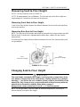
Measuring Seat-to-Floor Height ....................................................................................... .35
Changing Seat-to-Floor Height ........................................................................................ .35
SECTION 7—WHEEL BRAKES ................................................................................................ 37
Adjusting Wheel Brakes .................................................................................................... 37
Replacing Wheel Lock Handle ......................................................................................... .38
Installing/Adjusting Hub Brakes ....................................................................................... .39
SECTION 8—OPTIONS ............................................................................................................. 41
Installing/Adjusting Swing Away Tray ................................................................................ 41
Installing/Adjusting Headrest ............................................................................................ .42
SECTION 9—ANTI-TIPPERS ................................................................................................... 43
Installing/Adjusting Simple Anti-Tippers ........................................................................... 43
Installing/Adjusting Anti-Tippers with tipping Aid ............................................................. .44
Adjusting Anti-Tippers ....................................................................................................... .45
SECTION 10—PERIODIC MAINTENANCE GUIDELINES ........................................................ 46
Initially ................................................................................................................................. 46
Weekly/Monthly/Annually .................................................................................................. 47

4
SECTION 1—MAINTENANCE GUIDELINES
SECTION 1—TROUBLESHOOTING
A N D M A IN T E N A N C E G U I DE L IN E S
General Information
User manual and pre-sales information:
For pre-sales information and user manual related to this wheelchair, please consult the
www.invacare.eu.com website.
Adjustment and/or combination of options with wheelchair configuration:
Always refer to appropriate European Prescription Form (EPF) when you intend to adjust
or to add an option. In the EPF there is a list of non-compatibilities that you may consult
before any change of configuration or adjustment. Please contact your Invacare local
contact for further information.
NOTE: Please recommend the user to follow the rules mentioned in the User Manual
about Maintenance Schedule, Cleaning and Troubleshooting sections.
Troubleshooting:

SECTION 1— MAINTENANCE GUIDELINES
5
C A U T I O N
It is compulsary to use original Invacare spare parts which you can obtain from any
Invacare subsidiaries. A list of spare parts is available at www.invacare.eu.com
W A R N I N G
After ANY adjustments, repair or service and before use, make sure all attaching
hardware is tightened securely - otherwise injury or damage may occur.
C A U T I O N
DO NOT over tighten hardware attaching to the frame. This could cause damage to
could cause damage to the frame tubing.
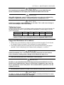
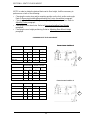
Tightening torques
The tightening torques stated in the following table are dependent on the thread diameters for
the nuts and bolts for which no special values are determined. All values apply to dry and
grease-free threads.
Thread
M4
M5 M6 M8 M10/12
Tightening torque
in Nm mini/max
1,5/3 Nm 3/6 Nm 7/12 Nm
10/20 Nm
20/30 Nm
Caution: All other nuts not noted here must be tightened FINGERTIGHT!
Suggested Maintenance Procedures
1. Before using your wheelchair, make sure all nuts and bolts are tight. Check all parts
for damage or wear and replace. Check all parts for proper adjustment.
2. Keep quick release axles free of dirt and lint to ensure positive locking and proper
operation. Refer to Adjusting Quick
Release Axles paragraph, on section 5.
W A R N I N G
DO NOT use WD-40, 3-in- 1 oil, or other penetrating lubricants on quick-release
axles. Otherwise, binding and/or damage to the wheelchair may occur.
3. Clean quick
release axles once a week with a Teflon lubricant.
W A R N I N G
DO NOT use your wheelchair unless it has the proper tire pressure (BAR, KPa or P.S.I.).
DO NOT over inflate the tires. Failure to follow these suggestions may cause the
tire to explode and cause bodily harm. The recommended tire pressure is on the
sidewall of the tire.
4. Recommended tire pressure is listed on the sidewall of the tire (BAR, KPa or P.S.I.).
C A U T I O N
As with any vehicle, the wheels and tires should be checked periodically for cracks
and wear, and should be replaced if damaged.

SECTION 1— MAINTENANCE GUIDELINES & STABILITY WARNING
6
5. The wheels, castors and tires should be checked periodically for cracks and wear, and
should be replaced when necessary.
6. Regularly check for loose spokes in the rear wheels. If loose, have them adjusted.
7. Periodically check handrims to ensure they are secured to the rear wheels. Refer to
Replacing Handrims paragraph, on section 5.
8. Periodically check castor wheel bearings to make sure they are clean and free from
moisture. Use a Teflon
®
lubricant if necessary.
9. Check upholstery for sagging, rips or tears.
10. Clean upholstery with mild soap and water.
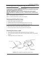
Stability Warning
The seat height, seat depth, back angle, seating system/upholstery, size/position of the
rear wheels, size/position of the front castors, seating options (e.g. headrest, back
bag,…) as well as the user condition directly relate to the stability of the wheelchair.
Any change to one or any combination of the nine may cause the wheelchair to
increase/decrease in stability.
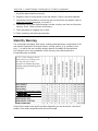
Seat-to-floor heights have specific positions depending on rear wheel size, rear wheel
position, front caster size/position and seat-to-floor angle.
CASTOR SIZE
CASTOR POSITION

SECTION 2—FRONT HANGERS
7
SECTION 2—FRONT HANGERS
W A R N I N G
After ANY adjustments, repair or service and before use, make sure all
attaching hardware is tightened securely - otherwise injury or damage may
occur.
A 50 mm clearance between the bottom of the footplate and the ground/floor MUST
be maintained at all times.
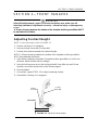
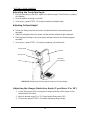
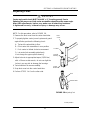
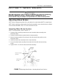
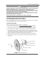
Adjusting Footrest Height
NOTE: For this procedure, refer to FIGURE 2.1.
1. Remove calf strap, if so equipped.
2. Unscrew locking screw and or locking bolt.
3. Position the footrest assembly to the desired height.
NOTE: A 50 mm clearance between the bottom of the footplate and the ground/floor
MUST be maintained at all times.
4. If the distance between the bottom of footplate and the ground/floor is not 50 mm
minimum, adjust footrest tube accordingly.
5. Using the locking screw and or the locking bolt with 5 mm Allen key and 10 mm
Spanner, secure the footrest tube to the footrest support.
6. Securely tighten.
7. If necessary, repeat STEPS 2
-
5 to adjust remaining footrest.
8. Reinstall the calf strap, if so equipped.
FIGURE 2.1 Adjusting Footrest Height
50 mm mini
Locking
Bolt (M6)
Locking
Screw (M6)

SECTION 2—FRONT HANGERS
8
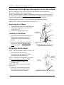
Replacing Heel Strap
NOTE: For this procedure, refer to FIGURE 2.2.
1. Remove the locking bolt (5 mm Allen key and 10 mm Spanner) that secure the
footrest tube to the footrest support.
2. Remove the lower footrest assembly.
3. Remove the mounting screw, strap pin that
secure the heel strap to the footplate.
4. Slide heel strap over footrest tube.
NOTE: When securing the heel strap to the
footrest assembly, tighten the mounting screw
and strap pin until they are secure.
5. Using the mounting screw, strap pin, secure
the heel strap to the footplate.
6. Using the locking bolt with 5 mm Allen key and
10 mm Spanner, secure the footrest tube to the
footrest support.
7. Securely tighten (5 Nm).
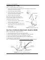
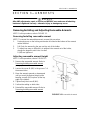
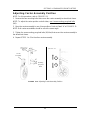
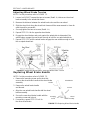
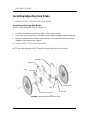
One Piece Footboard Adjustments (Depth & Width)
NOTE: For this procedure, refer to FIGURE 2.3.
1. Loosen Mounting Screw (M6) securing the depth position.
2. Adjust to desired depth (3 positions), firmly tighten Mounting Screw (M6).
3. Loosen 4 Locking Bolts (M5) securing the footboard central part.
4. Slide outside parts to the desired width using the pre-set width position.
5. Firmly tighten 4 Locking Bolts (M5).
NOTE: For angle adjustment refer to Installing Angle Adjustable Footplate paragraph.
Locking bolt (M6)
Strap pin
Mounting screw
Heel strap
FIGURE 2.2 Replacing Heel Strap
Locking
Bolt (M5)
Mounting
Screw (M6)
FIGURE 2.3 One Piece Footboard Adjustments
3 depth
positions
Pre-set width
position
Footboard
Central Part

SECTION 2—FRONT HANGERS
9
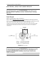
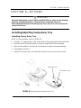
Installing Angle Adjustable Footplate
NOTE: For this procedure, refer to FIGURE 2.4.
NOTE: This procedure is for individual Angle Adjustable Footrests only.
1. Position the angle adjustable footplate on the footrest support tube at the desired
height.
2. Using the locking screw, loosely secure the angle adjustable footplate to the
footrest support tube.
NOTE: Refer to Adjusting Footrest Height paragraph.
3. Using the mounting screw, adjust to the desired angle (Tooth Plates) by rotating the
footplate and depth by sliding the footplate into the tooth plates support.
4. Using the mounting screw (M6), secure the Angle Adjustable Footplate to the
footrest tube. Securely tighten.
5. If necessary, repeat STEPS 1
-
4 to adjust remaining Angle Adjustable Footplate.
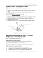
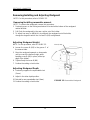
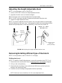
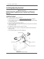
Adjusting Elevating Legrest Angle, Footplate
height/angle and Calf pad Height
NOTE: For this procedure, refer to FIGURE 2.5.
Adjusting the Legrest Angle
1. Loosen Locking Knob securing the rotating axle of the elevating legrest.
2. Adjust to desired angle, firmly tighten Locking Knob.
3. If necessary, repeat STEPS 1-2 to adjust remaining elevating legrest angle.
Adjusting the Footplate Height
1. Loosen Knob securing the slide tube to the elevating legrest.
2. Adjust into one of preset positions and firmly tighten the Knob (5 Nm).
3. If necessary, repeat STEPS 1
-
2 to adjust remaining footplate height.
Tooth Plates
Mounting Screw (M6)
Angle Ajustable Footplate
FIGURE 2.4 Installing Angle Adjustable Footplate

SECTION 2—FRONT HANGERS
10
Adjusting the Footplate Angle
1. Using the mounting screw (M6), adjust to the desired angle (Tooth Plates) by rotating
the footplate.
2. Securely tighten mounting screw (M6).
3. If necessary, repeat STEPS 1-2 to adjust remaining footplate angle.
Adjusting Calf pad Height
4. Loosen the fixing screw that secure the calf pad bracket to the elevating legrest
assembly.
5. Slide the calf pad bracket up or down until the desired calf pad height is obtained.
6. Firmly tighten the fixing screw securing the calf pad bracket to the elevating legrest
assembly.
7. If necessary, repeat STEPS 1
-
3 to adjust remaining calf pad bracket.
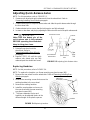
Adjusting the Hanger Abduction Angle (2 positions 0°or 30°)
1. Loosen fixing screw (M5) securing the locking mechanism of the hanger on the
vertical tube of the frame.
2. Adjust to desired angle (0° or 30°), firmly tighten fixing screw (M5).
3. If necessary, repeat STEPS 1-2 to adjust remaining hanger angle.
Calf pad
Knob
Fixing Screw
Mounting
Screw (M6)
Locking Knob
FIGURE 2.5 Adjusting Elevating Legrest Height and Calf pad Height

11
SECTION 3—ARMRESTS
S E C T I ON 3 —A RM R E S T S
W AR NI N G
After ANY adjustments, repair or service and BEFORE use, make sure all attaching
hardware is tightened securely - otherwise injury or damage may occur.
Removing/Installing and Adjusting Removable Armrests
NOTE: For this procedure, refer to FIGURE 3.1.
Removing/Installing removable armrest
NOTE: To remove the removable armrest, reverse this procedure.
1. Previously press on the locking mechanism A located at the bottom of the armrest
vertical bracket.
2. Pull /Push the armrest by the arm cushion out of the holder.
3. To adjust how easy or difficult it is to pull/push the armrest out of the holder,
change the degree to which the 4 screws
D (M6) are tightened.
Adjusting removable armrest Height
NOTE: For this procedure, refer to FIGURE 3.1.
1. Remove the removable armrest. Refer to
Removing/Installing removable armrest
paragraph.
2. Loosen the screw B (M6) in the groove C of
the armrest tube.
3. Move the armrest upwards or downwards
until you reach the desired height, while
keeping screw B (M6) in place (at the top
edge of the holder).
4. Tighten firmly the screw B (M6).
5. Perform the setting on both sides.
6. Reinstall the removable armrest. Refer to
Removing/Installing removable armrest
paragraph.
FIGURE 3.1
Removable Armrest

SECTION 3—ARMRESTS
12
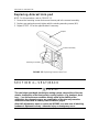
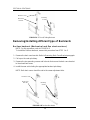
Removing/Installing and Adjusting Mudguard
NOTE: For this procedure, refer to FIGURE 3.2.
Removing/Installing removable armrest
NOTE: To remove the mudguard, reverse this procedure.
1. Previously press on the locking mechanism A located at the bottom of the mudguard
vertical bracket.
2. Pull /Push the mudguard by the arm cushion out of the holder.
3. To adjust how easy or difficult it is to pull/push the mudguard out of the holder,
change the degree to which the 4 screws D (M6) are tightened.
Adjusting Mudguard Height
NOTE: For this procedure, refer to FIGURE 3.2.
4. Loosen the screw B (M6) in the groove C of
the armrest tube.
5. Move the mudguard upwards or downwards
until you reach the desired height, while
keeping screw B (M6) in place (at the top
edge of the holder).
6. Tighten firmly the screw B (M6).
7. Perform the setting on both sides.
Adjusting Mudguard Depth
8. Previously suppress the expandable rivet
(5 mm).
9. Adjust in the other depth position.
10. Reinstall a new expandable rivet (5mm).
11. Perform the setting on both sides.
FIGURE 3.2 Removable Mudguard
Rivet (5 mm)

13
SECTION 3—ARMRESTS
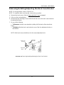
Replacing Armrest Arm pad
NOTE: For this procedure, refer to FIGURE 3.3.
1. Remove the mounting screws that secure the arm pad to the armrest assembly.
2. Replace arm pad and securely tighten with the existing mounting screws (M5).
3. Repeat STEPS 1
-
2 for the opposite side if necessary.
FIGURE 3.3 Replacing Armrest Arm Pad
SECTION 4—SEAT/BACK
W A R N I N G
The seat height, seat depth, back angle, seating system, size/position of the rear
wheels, size/position of the front castors, seating options (e.g. headrest, back
bag, …) as well as the user condition directly relate to the stability of the
wheelchair. Any change to one or any combination of the nine may cause the
wheelchair to decrease in stability. Refer to table on page 6.
After ANY adjustments, repair or service and BEFORE use, make sure all attaching
hardware is tightened securely - otherwise injury or damage may occur.
Armrest assembly
Mounting screw (M5)
Armpad

SECTION 4—SEAT/BACK
14
Removing Back Cane
NOTE: For this procedure, refer to FIGURE 4.1.
1. Remove the mounting screw and locknut (M6) that secures the back cane to the back
cane bracket.
2. Repeat STEP 1 for the other back cane.
3. Remove the back canes out of the back cane brackets.
Removing/Installing Seat Upholstery
NOTE: For this procedure, refer to FIGURE 4.2.
NOTE: To install the seat upholstery, reverse this procedure.
1. Fold the wheelchair.
2. Remove the mounting screw (Torx) that secures the upholstery to the front and back rails.
3. Remove the end caps from the front of the seat rails.
4. Slide the seat upholstery out of the seat rails.
FIGURE 4.2 Removing/Installing Seat Upholstery
FIGURE 4.1
Removing Back Canes

15
SECTION 4—SEAT/BACK
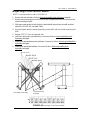
Adjusting Cross Brace Width
NOTE: For this procedure, refer to FIGURE 4.3.
1. Remove the seat upholstery. Refer to Removing/Installing Seat Upholstery paragraph.
2. Remove the two mounting screw (M6) that secures the upper part of the cross brace and the
central mounting bolt (M8).
3. Slide upper parts equally on both side to the desired width using the pre-set width positions.
(refer to the FIGURE 4.6, see Width Table).
4. Securely tighten with the existing mounting screw (M6) and the central mounting bolt
(M8).
5. Repeat STEPS 1
-
4 for the opposite side.
6. Install the appropriate seat upholstery, if necessary. Refer to Removing/Installing Seat
Upholstery paragraph.
7. Installing the appropriate backrest upholstery, if necessary. Refer to Removing/Installing Back
Upholstery paragraph.
8. Installing the appropriate footplate, if necessary. Refer to Removing/Installing Back
Upholstery paragraph
FIGURE 4.3
Adjusting Cross Brace Width
2 Mounting screws (M6)
Central Mounting
Bolt (M8)

SECTION 4—SEAT/BACK
16
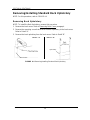
Removing/Installing Standard Back Upholstery
NOTE: For this procedure, refer to FIGURE 4.4.
Removing Back Upholstery
NOTE: To Install the Back Upholstery, reverse this procedure.
1. Remove the back canes. Refer to Removing Back Canes paragraph.
2. Remove the mounting screw that secures the back upholstery to the back canes.
Refer to Detail “A”.
3. Remove the back upholstery from the back canes. Refer to Detail “B”.
FIGURE 4.4 Removing/Installing Standard Back Upholstery
Back Cane
DETAIL “A”
DETAIL “B”
Upholstery

SECTION 4—SEAT/BACK
17
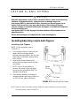
Contour (adjustable) Back Upholstery
Contour (adjustable) Tension Strips
The adjuster strips can be adjusted at various levels of tension to accommodate
individual end
users. In a typical scenario, the bottom two strips can be adjusted tightly to
support and/or assist the extensor muscles.
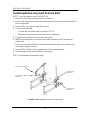
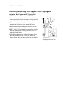
Installing/Replacing Adjustable Back Upholstery
NOTE: For this procedure, refer to FIGURE 4.5, next page.
Installing
1. Remove the existing back upholstery from the wheelchair. Refer to
Removing/Installing Standard Back Upholstery paragraph.
2. Slide each section (anchor loop/adjuster strap) of the adjustable back upholstery with
the grommet hole facing the rear of the wheelchair.
3. Secure the adjustable back upholstery to the back canes with the two mounting
screws.
NOTE: Clean the upholstery with warm water and mild detergent to remove superficial
soil.
W A R N I N G
Ensure that the wheelchair is fully opened, the back brace is fitted and the seat
rails properly located. The fastening straps MUST be securely fastened before
applying the back upholstery cover. The Contour (adjustable) back should be
checked whenever entering the wheelchair to ensure that the fastening strips are
securely fastened.
4. Slip adjuster straps through corresponding anchor loops and adjust the back
upholstery. Secure with the fastening strips.
5. Secure the back upholstery cover (fastening strap) to the back of the adjustable back
upholstery (fastening strap).
6. Flip the back upholstery cover over the adjustable back upholstery and secure the
fastening strips to the front of the adjustable back upholstery.
7. Lay the front portion of the back upholstery cover on the seat upholstery.
8. Adjust the slack in the back upholstery cover and then secure to the seat upholstery.

SECTION 4—SEAT/BACK
1
8
Replacing
1. Lift up on the existing back upholstery cover and remove the cover from the
wheelchair.
2. Remove the two mounting screws and washers that secure the existing adjustable
back upholstery to the back canes.
3. Slide each section (anchor loop/adjuster strap) of the existing adjustable back
upholstery off of the back canes.
4. Slide each section (anchor loop/adjuster strap) of the new adjustable back upholstery
with the grommet hole facing the rear of the wheelchair.
5. Secure new adjustable back upholstery to the back canes with the two mounting
screws and washers.
W A R N I N G
Ensure that the wheelchair is fully opened, the back brace is fitted and the seat
rails properly located. The fastening strips MUST be securely fastened before
applying the back upholstery cover. The Contour (adjustable) back should be
checked whenever entering the wheelchair to ensure that the fastening strips are
securely fastened.
6. Slip adjuster strips through corresponding anchor loops and adjust the back
upholstery. Secure with the fastening strips.
7. Secure the new back upholstery cover (fastening strap) to the back of the new
adjustable back upholstery (fastening strap).
8. Flip the new back upholstery cover over the new adjustable back upholstery and
secure the fastening strips to the front of the new adjustable back upholstery.
9. Lay the front portion of the new back upholstery cover on the seat upholstery.
10. Adjust the slack in the new back upholstery cover and then secure to the seat
upholstery.
FIGURE 4.5 Installing/Replacing Contour (adjustable) Back Upholstery
Back brace

SECTION 4—SEAT/BACK
19
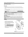
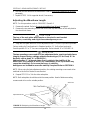
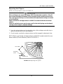
Adjusting the Height Adjustable Back
NOTE: For this procedure, refer to FIGURE 4.6.
1. Loosen, but DO NOT remove, the height adjustment knobs.
2. Reposition the back canes to the desired height.
NOTE: Both back canes should be adjusted to the same height.
NOTE: DO NOT raise push handles to maximum height when tilting the chair.
3. Tighten the height adjustment knobs.
NOTE: To prevent accidental removal of a back cane, the spring button lock will engage
at the full extension of the back cane. To disengage the button, press the button located
below the height adjustment, under the upholstery, on the back cane (Detail “A”).
FIGURE 4.6 Adjusting the Height Adjustable Backrest cane
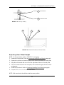
Removing/Installing different type of Backrests
NOTE: For this procedure, refer to FIGURE 4.7, next page.
Folding backrest
NOTE: To Install the Fixed/Folding backrest, reverse this procedure from STEP 3 to 1.
1. Remove the back cane bracket. Refer to Removing Back Cane Bracket paragraph.
2. Pull up on the seat upholstery.
3. Remove the two mounting screws and locknuts (M6) that secure the back cane
bracket to the wheelchair frame.
4. Install the new set including the appropriate backrest upholstery
NOTE: Both back canes should be set to the same adjustment hole.
Back
cane
Backrest
Upholstery
Height Adjustment
Knob
DETAIL “A” - SNAP
BUTTON LOCK
Location of Snap
button lock
(under Upholstery)

SECTION 4—SEAT/BACK
20
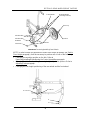
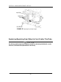
Removing/Installing different type of Backrests
Recliner backrest (Mechanical and Gas strut versions)
NOTE: For this procedure, refer to FIGURE 4.8.
To Install the Recliner backrest, reverse this procedure from STEP 1 to 3.
1. Remove the back cane bracket. Refer to Removing Back Cane Bracket paragraph.
2. Pull up on the seat upholstery.
3. Remove the two mounting screws and locknuts that secure the back cane bracket
to the wheelchair frame.
4. Install the new set including the appropriate backrest upholstery
NOTE: Both back canes should be set to the same adjustment hole.
Backrest Cane
Back Cane
Bracket
Mounting
Screws
FIGURE 4.7 Fixed/Folding Backrest
Mounting
Sc
rews
Back Cane
Bracket
Backrest Cane
FIGURE 4.8 Recliner Backrests
Page is loading ...
Page is loading ...
Page is loading ...
Page is loading ...
Page is loading ...
Page is loading ...
Page is loading ...
Page is loading ...
Page is loading ...
Page is loading ...
Page is loading ...
Page is loading ...
Page is loading ...
Page is loading ...
Page is loading ...
Page is loading ...
Page is loading ...
Page is loading ...
Page is loading ...
Page is loading ...
Page is loading ...
Page is loading ...
Page is loading ...
Page is loading ...
Page is loading ...
Page is loading ...
Page is loading ...
Page is loading ...
Page is loading ...
-
 1
1
-
 2
2
-
 3
3
-
 4
4
-
 5
5
-
 6
6
-
 7
7
-
 8
8
-
 9
9
-
 10
10
-
 11
11
-
 12
12
-
 13
13
-
 14
14
-
 15
15
-
 16
16
-
 17
17
-
 18
18
-
 19
19
-
 20
20
-
 21
21
-
 22
22
-
 23
23
-
 24
24
-
 25
25
-
 26
26
-
 27
27
-
 28
28
-
 29
29
-
 30
30
-
 31
31
-
 32
32
-
 33
33
-
 34
34
-
 35
35
-
 36
36
-
 37
37
-
 38
38
-
 39
39
-
 40
40
-
 41
41
-
 42
42
-
 43
43
-
 44
44
-
 45
45
-
 46
46
-
 47
47
-
 48
48
-
 49
49


Ask a question and I''ll find the answer in the document
Finding information in a document is now easier with AI
Related papers
-
Invacare Alu Lite User manual
-
Invacare Action XT User manual
-
-
Invacare MyOn HC User manual
-
-
-
-
-
-
Other documents
-
Boss Office Products B9533C-GY Operating instructions
-
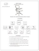 BestOffice Ergonomic Office Chair Gaming Installation guide
-
Luxor Pro Gaming Chair User manual and assembly instructions
-
Boss Office Products B686 Operating instructions
-
Midmark 641 Power Procedures Chair Installation guide
-
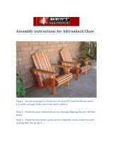 Best Redwood ADCHB-NS Operating instructions
-
 Furniture of America IDF-3342BR-LV Installation guide
-
 Furniture of America IDF-3342BR-LV Installation guide
-
L.A. Steelcraft LA-PN204-RB15 Installation guide
-


