Page is loading ...

INSTALLATION INSTRUCTIONS
69-2685ES-07
HE240, HE280 Humidifier
SAVE THIS DOCUMENT
FOR FUTURE REFERENCE
READ BEFORE INSTALLING
M33322A

HE240, HE280 HUMIDIFIER
69-2685ES—07 2
Safety Definitions
These safety terms identify information you must read prior to installing or operating the humidifier.
WARNING
Indicates a hazardous situation which, if not avoided, could result in death or serious injury.
CAUTION
Indicates a hazardous situation which, if not avoided, could cause bodily injury or property damage.
Safety Precautions
Make sure you read and understand the following safety hazards before installing, using, or working with the
humidifier:
WARNING
Serious Personal Injury Hazard.
Can cause electrical shock and injury from moving parts.
Disconnect power and shut off water supply before removing cover.
WARNING
Hazardous Voltage
Can cause personal injury or equipment damage.
Do not cut or drill into any air conditioning or electrical accessory.
CAUTION
Chemical Hazard.
Can cause personal injury or equipment damage.
Do not use any line connected to an air conditioner.
Do not use gas line.
CAUTION
Temperature and Static Pressure Hazard.
Can cause property or equipment damage.
Locate humidifier where ambient temperature is between 32 and 120 °F (0 to 49 °C).
Do not install humidifier where freezing temperatures could occur.
Be sure supply plenum static pressure is no greater than 0.4 in. wc and water pressure is no greater than
120 psi.
CAUTION
Sharp Edges Installation Hazard.
Can cause personal injury.
Wear gloves and safety glasses.

HE240, HE280 HUMIDIFIER
3 69-2685ES—07
IMPORTANT
Read and save these instructions.
WELCOME
Congratulations on your purchase of an HE240 or HE280 whole-house humidifier. Proper use of a whole-house
humidifier has numerous benefits related to your family’s health and comfort, as well as helping to safeguard
and protect your home.
How Your Humidifier Works
HE240 and HE280 humidifiers use the principle that vapor (evaporated water) is created when warm air blows
over a water-soaked area. As the vapor circulates, the relative humidity rises.
Your humidity control monitors the relative humidity and activates the humidifier accordingly. The humidifier
has a water supply that dispenses water evenly over a humidifier pad. The warm dry air from the furnace passes
over the humidifier pad and picks up the moist air to circulate it throughout your home.
Humidified air feels warmer and more comfortable so you may be able to lower your thermostat heating
setpoint, which saves money on your heating fuel bills. The end result is that your humidifier gives you a
comfortable environment that is also energy efficient.
Model Specific Features
The HE280 humidifier has water savings technology built in that could save up to 30% versus leading brands.
This translates to up to 20 gallons of water saved per day!
PREPARING FOR THE INSTALLATION
Be sure you have the required tools and accessories from Table 1 and in the Suggested tools and accessories list
before beginning the installation.
Included Accessories
Suggested Tools and Accessories
Tools and accessories required for installation include:
• Tin snip
•Screwdriver
•Pliers
• Adjustable or open-end wrench
•Drill
• Level
• 3/4 in. (19 mm) sheet metal drill bit
• 6 in. (155 mm) diameter flexible duct
• 6 in. (155 mm) duct collar
• 18 gauge, two-strand thermostat wire
• 1/4 in. (6.35 mm) OD feed water tubing
• 1/2 in. (12.7 mm) ID drain tubing
•Foil tape roll
• Code-compliant 1/4 in. (6.35 mm) water shutoff valve and fittings
Table 1. Included Accessories.
Quantity Accessory
1 bag Connecting and mounting hardware:
4 mounting screws
1 drain tube clamp
1 H6062 Humidistat
1Plug-in transformer
1 bag 1 plastic elbow
1 grommet
1 connector strap
1 PVC tubing
1 wire nut
1Mounting template

HE240, HE280 HUMIDIFIER
69-2685ES—07 4
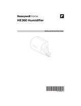
Determining Best Location for Humidifier
• Select a location for the humidifier on the supply (warm air stream) duct. See Fig. 1 for examples. Return duct
mounting is acceptable if there are space restrictions on the supply duct. If you are mounting the humidifier
on the return duct, simply swap “return duct” for “supply duct” throughout these instructions.
• Select a location that cannot damage the air conditioner A-coil during installation.
• Do not locate the humidifier on the furnace body.
• Mount the humidifier in a conditioned space to prevent freezing.
• Mount the humidifier at least 3 in. (78 mm) above the furnace body to allow adequate space for the solenoid
valve and drain line.
Fig. 1. Typical humidifier installation locations.
Fig. 2. Typical humidifier installation locations.
Selecting Location for Humidistat
• Select a location for the humidistat on the return plenum or on the wall in the living space.
• Mounting on the return plenum is the easiest installation for the control wiring circuit.
IMPORTANT
The humidistat must be mounted upstream from the humidifier or bypass duct to ensure it is properly
sensing the relative humidity of the living space. Locate the control at least 8 in. (203 mm) upstream from
the humidifier in the return air duct. (See Fig. 3.)
M12248E
HORIZONTAL
DOWN
FLO
LOWBOY
HIGHBOY
HUMIDIFIER
BYPASS
COLLAR
CHOOSE A LOCATION IN A CONDITIONED
SPACE THAT HAS ACCESS TO A WATER SUPPLY
PIPE. COLD OR HOT WATER CAN BE USED.
SELECT A SURFACE ON THE HVAC SUPPLY OR
RETURN DUCT WITH CLEARANCE FOR THE
SOLENOID VALVE, DRAIN LINE AND COVER
REMOVAL.
LOCATION MUST ALSO HAVE ACCESS TO 120
VAC POWER.
ENSURE THE LOCATION IS NEAR A DRAIN.
CONSULT LOCAL PLUMBING CODES FOR
PROPER DRAINAGE.
M33410A

HE240, HE280 HUMIDIFIER
5 69-2685ES—07
Fig. 3. Selecting duct location for humidistat.
Locating Closest 120 V Electrical Outlet
• Select location with access to an outlet. If not available, contact an electrician to have one installed.
• Make sure that the 18-gauge wire is adequate to reach from the humidifier to the humidistat, and also from
the humidifier to the transformer. Please note that the 18-gauge wire will need to be cut into the 2 correct
lengths. See “Wiring” on page 11 for more information.
INSTALLATION
1. Turn off power to the air handling system at the circuit breaker.
2. Draw a level line on the plenum in the selected location.
IMPORTANT
To ensure optimal product performance, be sure the mounting template is level before marking. Use of a
small level is recommended.
3. Locate the template (form number 69-2710 included in the box). For the HE240 model, cut out the tem-
plate along the dotted line.
4. Tape the template in position and trace around the template.
5. Remove the template and carefully cut the rectangular opening using tin snips.
6. Disassemble the humidifier; remove the cover and take out the humidifier pad assembly. See Fig. 4.
Fig. 4. Disassembling humidifier.
ALTERNATE
LOCATION
RETURN
AIR RETURN
AIR
6 IN (152 MM)
MINIMUM
15 IN (381 MM)
MINIMUM
BEST
LOCATION
RETURN
AIR DUCT
M34579B
M33323
WATER
FEED NOZZLE
FRAME
HUMIDIFIER
HOUSING
WATER
FEED TUBE
HUMIDIFIER
PAD ASSEMBLY
COVER
SIDEWALL
BY-PASS SIDEWALL

HE240, HE280 HUMIDIFIER
69-2685ES—07 6
7. Make sure the humidifier housing is level, then position it in the opening so the plastic tabs are in place on
the lower sheet metal edge of the opening. Use pliers, as necessary, to flatten cut edges. See Fig. 5.
Fig. 5. Installing humidifier on duct.
8. Secure the humidifier housing to the opening at the top and bottom using sheet metal screws.
9. Use the 6 in. (155 mm) starter collar as a template to mark the opening for the bypass. The starter collar
end can be identified by the pliable metal tabs.
10. Carefully cut the opening for the 6 in. (155 mm) starter collar end of the flex duct. See Fig. 6. Use a drill to
start the cut in the middle of the circle. Cut in an outward spiral to assist in controlling the cut.
Fig. 6. Cutting bypass opening.
11. Reassemble humidifier side plates to customize the orientation for your specific install. The side plate with
the humidifier port needs to be on the side of the humidifier that is closest to the 6 in. (155mm) hole cut in
Step 10.
12. Insert flex duct with starter collar into the 6" (155mm) hole that was cut in Step 10. Reach into hole
THROUGH THE FLEX DUCT so that the pliable metal tabs can be bent outwards into the hole. These tabs,
when bent outwards, will help secure the flex duct into your home's duct work.
13. Slide remaining loose end of flex duct over the humidifier port on the HE240/HE280, making sure that the
flex duct advances past the raised plastic tabs on the port. These tabs will help to hold the flex duct in
place. Verify that the damper blade has adequate clearance to move back and forth between the summer
and winter positions. Secure the flex duct in place with a connector strap.
DUCT
LEVEL
SHEET METAL
SCREWS (4)
PLASTIC
TABS (2)
DRAIN TUBING
M33324A
OPENING
TO AIR DUCT
STARTING
HOLE
6 IN. ROUND TEMPLATE
M20172

HE240, HE280 HUMIDIFIER
7 69-2685ES—07
14. Seal the duct connections with foil tape. Seal both
1) the connection between the starter collar end of the flex duct and the home's duct work and
2) the end of the flex duct to the humidifier over the top of the connector strap.
15. Reinstall the humidifier pad assembly in the humidifier housing.
16. Hinge the cover in place and secure with the thumbscrew located at the bottom of the cover.
Fig. 7. Connecting bypass ducting.
Connecting the Plumbing
Use hot or cold water and either hard or softened water in the humidifier.
NOTE: Using hot water will increase operating costs, but may provide a small increase in the amount of humid-
ity delivered.
IMPORTANT
Please consult local plumbing code for proper plumbing regulations before beginning. Use of a manual
shutoff valve may be required to meet code in your area.
1. Shut off the water.
2. Install the water shut off valve in the water supply line at the location selected per local code.
3. Use 1/4 in. (6 mm) OD copper pipe or tubing and connect the shut off valve to the inlet side of the solenoid
valve on the humidifier.
a. Insert the tubing into the solenoid valve fitting and support the valve while tightening the compression
nut.
b. Place the brass compression nut over the tubing.
c. Slide the plastic compression ring over the tubing. (Discard copper compression ring provided with
valve.)
d. Install brass insert into end of tubing.
Fig. 8. Installing feed tubing.
NOTE: To prevent leaking, use plastic (Delrin) compression rings with plastic tubing. Use copper sleeve rings
only with copper tubing.
e. Insert plastic supply tubing into quick connect fitting. Insert fully, and apply modest pull pressure to
ensure a tight fit.
4. Use the following steps to install a
1/2 in. (13 mm) drain tube between the humidifier and the floor drain (see
Fig. 9).
M33325A
HUMIDIFIER PORT
CONNECTOR STRAP
M39202
BRASS COMPRESSION NUT
PLASTIC
COMPRESSION
RING
BRASS INSERT
SOLENOID
VALVE

HE240, HE280 HUMIDIFIER
69-2685ES—07 8
a. Slide the drain clamp over the tubing.
b. Push the tubing over the drain nipple on the humidifier.
c. Hand-tighten the clamp around the tubing to secure it to the humidifier drain. The clamp is tightened
by compressing the two sides together so that one side fits into the ridged grove on the other side.
d. Secure the tubing (can use foil tape) along the route to prevent movement and ensure downward slope
for correct drainage.
Fig. 9. Installing the drain tubing.
NOTE: Cut tubing to correct length so the tubing terminates at the drain.
Connecting the Pressure Switch
1. If the humidifier is installed on the supply duct (as is recommended), the pressure switch needs to have
the tubing fed to the return duct. If the humidifier is installed on the return duct, the pressure switch needs
to have the tubing fed to the supply duct.
2. Drill a 3/4-in. (19 mm) diameter hole in the duct within 10 ft. (3 m) of the switch to ensure the provided
tubing reaches the pressure tap elbow.
Fig. 10. Pressure switch.
3. Insert the black rubber grommet into the duct hole.
4. Connect the tubing to the tubing fitting elbow and insert the tubing fitting elbow into the black rubber
grommet.
M20177A
M33405

HE240, HE280 HUMIDIFIER
9 69-2685ES—07
5. Connect the other end of the tubing to the applicable pressure connection on the switch.
a. If the humidifier is installed on the supply duct (as is recommended), the tube that inserts into the
humidifier needs to be attached to the black port, and the tube that runs to the return duct needs to be
attached to the gray port.
b. If the humidifier is installed on the return duct, the tube that inserts into the humidifier needs to be
attached to the gray port, and the tube that runs to the supply duct needs to be attached to the black
port.
Fig. 11. Installing the pressure switch tubing.
6. You may cut the tubing to fit the connection length between the elbow fitting and switch. It is also
recommended to secure the hose to existing structures to avoid accidental disconnection.
Installing the Humidistat
1. Separate wallplate from humidistat.
Fig. 12.
CAUTION
Electrical Hazard
Can cause electrical shock or equipment damage. Disconnect power before beginning installation.
M33326
M34565A
Setting
Light
Next Auto
System
%
Replace BattReplace Batt
Inside
%
HUMIDITY BOOST
PULL HERE

HE240, HE280 HUMIDIFIER
69-2685ES—07 10
2. Mark the duct-tube hole. Hold the wallplate up to the desired location on the duct and make a mark inside
the duct tube hole.
Fig. 13.
3. Drill the duct-tube hole. Find your mark and drill a 1/2 in. hole in the duct. This is where the duct tube will
be inserted to capture air.
Fig. 14.
4. Insert the duct tube. Insert the duct tube through the wallplate before securing to the duct.
Fig. 15.
M34580A
M34581C
M34671B

HE240, HE280 HUMIDIFIER
11 69-2685ES—07
5. Secure the wallplate. Secure the wallplate to the duct with sheet metal screws (provided).
Fig. 16.
6. Run wires through the back plate. Run wires through the top or bottom channel on the back plate when
ductmounted. If installing like a thermostat on a wall, run the wires through the back.
Fig. 17.
WIRING
CAUTION
Hazardous Voltage.
Can cause personal injury or equipment damage.
Disconnect power supply before installing or servicing equipment.
IMPORTANT
All wiring must comply with applicable local code, ordinances and regulations.
Wire the humidifier solenoid valve, humidistat and transformer. See Fig. 18.
Fig. 18. Wiring the controls and the HE240.
M34582B
M34610B
RUN WIRES
THROUGH THE
TOP OR BOTTO M
CHANN EL
C
R
U
U
S
S
M39013
C
R
U
U
S
S
24 VAC (CONSTANT)
OUTDOOR SENSOR
1
TRANSFORMER
WHITE WIRE
RED WIRE
5
HUMIDIFIER
SOLENOID
VALVE
RED WIRE
WHITE
WIRE
WHITE WIRE
RED WIRE
RED WIRE
RED WIRE
1
WIRE OUTDOOR SENSOR TO THE S TERMINALS.
USE A SHORT WIRE TO CONNECT R TO THE UPPER
U AS SHOWN.
2
2
WHITE
WIRE

HE240, HE280 HUMIDIFIER
69-2685ES—07 12
Fig. 19. Wiring the controls and the HE280.
1. Determine the length of wire necessary to run from the humidifier to the humidistat. Cut to length and
strip the ends appropriately.
2. Connect the red and white wires to the C and lower U terminals on the humidistat per the wiring diagram.
3. Taking the opposite end of the wire, connect RED WIRE to one terminal on the humidifier. Connect the
WHITE WIRE to the other terminal at the humidifier.
4. Using remaining wire, determine length needed to run from H6062 Humidistat to the transformer. Cut to
length and strip the ends appropriately.
5. With transformer unplugged, connect the red and white wires to the transformer by loosening the screws
on the transformer, wrap wire around screw post and then re-tighten the screws.
6. Taking the opposite end of the wire, connect the RED WIRE to the R terminal at H6062 and the WHITE
WIRE to C at H6062.
7. Cut a short wire. Connect one end of that wire to R and the other end to the upper U at H6062.
TESTING HUMIDIFIER OPERATION
Checklist
Humidifier is level.
Control wiring was reviewed using circuit diagram.
Transformer is plugged in.
Feed line has no kinks.
Drain line slopes continuously down and ends at floor drain.
Water hose inside humidifier is connected to PerfectFLO™ water distribution tray.
Tubing from pressure switch is not kinked or pinched.
After installation use the following steps to check the humidifier operation:
1. Turn on the power and the water supply
2. Ensure the shut off valve is fully opened. If saddle valve from HUMKIT is used, turn the handle to the left
(counter clockwise) until there is resistance.
3. Turn the H6062 all the way up and turn on the heat by setting the thermostat to 10 ºF (6 ºC) above room
temperature.
IMPORTANT
The furnace blower must be on to activate the humidifier.
4. Make sure that water is flowing out of the drain hose. If water does not flow, see Troubleshooting Your
Humidifier section.
5. Check for leaks.
6. Reset the thermostat and H6062 Humidistat to a comfortable setting for automatic operation. (35%
relative humidity is recommended.)
OPERATION
Controlling Your Humidity Settings
Your H6062 Humidistat controls your humidifier.
• Choose the humidity control setting using the combination of relative humidity/outdoor temperature setting
scale on your humidity control dial.
• When the outdoor sensor is used, the H6062 will optimize the humidity level while reducing moisture
condensation on the windows. See the H6062 instructions for settings and adjustments.
M39014
1
WIRE OUTDOOR SENSOR TO THE S TERMINALS.
USE A SHORT WIRE TO CONNECT R TO THE UPPER
U AS SHOWN.
C
R
U
U
S
S
24 VAC (CONSTANT)
OUTDOOR SENSOR
1
TRANSFORMER
WHITE WIRE
RED WIRE
5
HUMIDIFIER
SOLENOID
VALVE
RED
WIRE
WHITE
WIRE
WHITE WIRE
RED WIRE
RED WIRE
RED WIRE
WHITE
WIRE
2
2

HE240, HE280 HUMIDIFIER
13 69-2685ES—07
NOTE: If the outdoor sensor is not used with H6062, as the outside temperature drops, a lower humidity set-
ting is recommended to accommodate dewpoint effects. These settings should reduce the accumula-
tion of moisture and ice on windows and other areas of the home.
• Adjust the humidity control setting to adjust for indoor activities such as cooking, showering and clothes
drying, which can cause excessive levels of humidity that can accumulate moisture on your windows.
NOTE: If these activities persist for more than a few hours, set the humidity control to the lowest setting to turn
off the humidifier. If the condition does not improve, ventilate your home to remove the moisture.
MAINTAINING YOUR HUMIDIFIER
A regular maintenance program prolongs the life of your humidifier and makes your home more comfortable.
The frequency of cleaning depends on the condition of your water.
You can use either hard or soft water in your humidifier, but hard water mineral deposits are more difficult to
clean than soft water deposits.
Use the following procedure to clean your humidifier.
IMPORTANT
Never oil any part of the humidifier.
Once per year, depending on water quality
(either at the beginning or the end of the humidification season)
1. Disconnect the power by unplugging the transformer from the outlet and turn off the humidifier’s water
supply at the shut off valve.
2. Remove the humidifier cover. See Fig. 20 on page 14.
3. Remove the humidifier pad assembly from the humidifier by grasping the top of the tray and pulling it
toward you.
4. Pull one side of the humidifier pad assembly frame toward you and remove the tray from the frame.
5. Gently pinch the water nozzle prongs (a pair of prongs is located on each side of the PerfectFLO™ water
distribution tray) inward until you can lift the water nozzle off the tray.
6. Slide the humidifier pad out of the frame and discard the pad. It is recommended to replace the humidifier
pad on an annual basis. However, if your home has hard water, the pad may need to be replaced more
frequently.
7. Carefully remove any mineral deposits from the tray and frame. Be sure the frame drain hole has nothing
blocking it.
8. Disconnect the drain hose from the drain fitting on the bottom of the humidifier housing.
9. Clean the drain fitting, if necessary.
10. Bend the drain hose to loosen any mineral deposits.
11. Flush the drain hose with pressurized water (a running tap) to clean the hose.
12. Reattach the drain hose to the drain fitting.
13. Slide a new humidifier pad back into the frame.
14. Snap the water nozzle back on the tray.
15. Reattach the tray to the frame.
16. Place the humidifier pad assembly in the humidifier housing and press until the assembly is completely
seated. Be careful not to pinch or kink the water feed tube.
17. Replace the humidifier cover.
18. Verify the humidifier operation by following the steps in the Checking Your Humidifier for Correct
Operation section.
Table 2. Setting Your Humidistat when outdoor sensor is not used.
When Outside Temperature is: Use This Control Setting:
-20 °F (-29 °C) 15
-10 °F (-23 °C) 20
0 °F (-18 °C) 25
+10 °F (-12 °C) 30
+20 °F (-7 °C) 35
Above 20 °F (-7 °C) 40

HE240, HE280 HUMIDIFIER
69-2685ES—07 14
Fig. 20. Cleaning your humidifier.
End of Humidification Season
• Clean the humidifier and shut it off at the end of the heating season.
• Turn the water off at the shut off valve.
• Turn the H6062 to off.
• Turn the damper blade to the "summer" position.
IMPORTANT
Be sure the humidifier power is off.
Replacement Humidifier Pads
It is recommended to replace the humidifier pad on an annual basis. However, if your home has hard water, the
pad may need to be replaced more frequently because of the buildup of minerals diminishing its ability to
operate normally. If there is access to a water softener, it is recommended to use softened water.
Vacation
• When leaving on vacation, turn off the humidifier water supply and your humidistat.
• When you return, turn on the humidifier water supply and reset your humidistat.
Start of the Humidification Season
Use the following steps to bring the humidifier back to normal (winter) operation:
1. Turn damper blade to "winter" position.
2. Plug the humidifier transformer back into wall outlet and turn water supply to the humidifier back on at
shut off valve.
3. Turn the humidistat to its highest setting and set the thermostat to 10 °F (6 °C) above the room
temperature.
4. Observe that water is flowing out of the drain hose.
Table 3. Replacement pad part numbers.
Humidifier Model Replacement Pad
HE240 HC22P
HE280 HC26P
M33328A
PerfectFLO™ WATER
DISTRIBUTION TRAY
HUMIDIFIER PAD ASSEMBLY
WATER FEED NOZZLE
HUMIDIFIER HOUSING
SIDEWALL
BYPASS
SIDEWALL
COVER
WATER FEED TUBE

HE240, HE280 HUMIDIFIER
15 69-2685ES—07
NOTE: The furnace blower must be running to activate the humidifier.
5. Reset the thermostat and humidistat to a comfortable setting for automatic operation. (35% relative
humidity is recommended.)

HE240, HE280 HUMIDIFIER
69-2685ES—07 16
TROUBLESHOOTING YOUR HUMIDIFIER
Table 4. Troubleshooting Humidifier.
Problem What to look for What to do
Water
leakage Leaking joints. Shut off water and tighten connections.
Brass tubing inserts Verify that brass tubing inserts are used.
Saddle valve leaking. If a saddle valve is used as the shut off valve, verify rubber pad is installed
on saddle valve.
No water to
drain. Electrical Verify control circuit wiring.
Check all connections.
Humidistat Turn the humidistat up all the way. If “Humidity Boost” appears on the
screen the H6062 is calling for humidity. If it does not, the installer might
not have enabled boost and it is possible very cold outdoor temperatures
could be restricting humidity.
Humidifier power Verify that outlet has power.
Solenoid After verifying other wiring components, turn on furnace fan, turn
humidistat up and down, and listen for solenoid to click.
Plumbing Verify plumbing connections.
Check for kinks. Verify shut off valve is in open position.
Shut off valve Verify shut off valve is turned on. If a saddle valve is used, verify that needle
pierces water line and then backs out needle to open valve.
Humidifier Remove cover and verify that water flows into distribution tray.
Drain tubing Verify no obstructions.
Air leakage Check duct joints Seal with foil tape.
Low
humidity Furnace blower not
operating. •Reset circuit breaker or check for blown fuse.
•Check that the furnace power is on.
•Check all external wiring connections.
•Check the humidity control setting.
•Verify that pressure switch tubing isn't pinched or obstructed.
•Call a professional heating contractor.
Rapid air changes.
Drafts (cold air is dry
and is an added load
to the humidifier).
•Keep doors and windows closed.
•Close fireplace damper when not in use.
•Keep exhaust fan running time to a minimum.
•Seal around doors and windows.
Damper in “summer”
position. •Set damper blade to "winter" position to allow humidification.
High
humidity Condensation on
walls. •Turn off humidity control and water until condensation is completely
evaporated.
Heavy condensation
on windows. •The H6062 can be set for frost control if outdoor sensor is used. If
already set for window protection. If frost protection is enabled, and you
still get condensation, lower the setting on the H6062.

HE240, HE280 HUMIDIFIER
17 69-2685ES—07
1-YEAR LIMITED WARRANTY
Resideo warrants this product, excluding battery, to be free from defects in workmanship or materials,
under normal use and service, for a period of one (1) year from the date of first purchase by the original
purchaser. If at any time during the warranty period the product is determined to be defective due to
workmanship or materials, Resideo shall repair or replace it (at Resideo's option).
If the product is defective,
(i) return it, with a bill of sale or other dated proof of purchase, to the place from which you purchased it;
or
(ii) call Resideo Customer Care at 1-800-468-1502. Customer Care will make the determination
whether the product should be returned to the following address: Resideo Return Goods, 1985
Douglas Dr. N., Golden Valley, MN 55422, or whether a replacement product can be sent to you.
This warranty does not cover removal or reinstallation costs. This warranty shall not apply if it is shown
by Resideo that the defect was caused by damage which occurred while the product was in the
possession of a consumer.
Resideo's sole responsibility shall be to repair or replace the product within the terms stated above.
RESIDEO SHALL NOT BE LIABLE FOR ANY LOSS OR DAMAGE OF ANY KIND, INCLUDING ANY
INCIDENTAL OR CONSEQUENTIAL DAMAGES RESULTING, DIRECTLY OR INDIRECTLY, FROM ANY
BREACH OF ANY WARRANTY, EXPRESS OR IMPLIED, OR ANY OTHER FAILURE OF THIS PRODUCT.
Some states do not allow the exclusion or limitation of incidental or consequential damages, so this
limitation may not apply to you.
THIS WARRANTY IS THE ONLY EXPRESS WARRANTY RESIDEO MAKES ON THIS PRODUCT. THE
DURATION OF ANY IMPLIED WARRANTIES, INCLUDING THE WARRANTIES OF MERCHANTABILITY
AND FITNESS FOR A PARTICULAR PURPOSE, IS HEREBY LIMITED TO THE ONE YEAR DURATION OF
THIS WARRANTY. Some states do not allow limitations on how long an implied warranty lasts, so the
above limitation may not apply to you.
This warranty gives you specific legal rights, and you may have other rights which vary from state to
state. If you have any questions concerning this warranty, please write Resideo Customer Care, 1985
Douglas Dr, Golden Valley, MN 55422 or call 1-800-468-1502.

HE240, HE280 HUMIDIFIER
© 2022 Resideo Technologies, Inc. All rights reserved.
The Honeywell Home trademark is used under license from Honeywell International, Inc. This product is manufactured by Resideo Technologies, Inc. and its affiliates.
www.resideo.com
Resideo Technologies, Inc.
1985 Douglas Drive North, Golden Valley, MN 55422
1-800-468-1502
69-2685ES—07 M.S. Rev. 09-22 | Printed in United States

INSTRUCCIONES DE INSTALACIÓN
69-2685ES-07
Humidificadores HE240 o
HE280
GUARDE ESTE DOCUMENTO
PARA REFERENCIA FUTURA
LEER ANTES DE INSTALAR
M33322A

HUMIDIFICADORES HE240 O HE280
69-2685ES—07 2
Definiciones de seguridad
Estos términos de seguridad identifican la información que deberá leer antes de instalar o utilizar el
humidificador.
ADVERTENCIA
Indica una situación peligrosa que, si no se evita, podría ocasionar la muerte o lesiones graves.
PRECAUCIÓN
Indica una situación peligrosa que, si no se evita, podría ocasionar lesiones físicas o daño a la propiedad.
Precauciones de seguridad
Lea y comprenda los siguientes peligros que amenazan la seguridad antes de instalar, utilizar o trabajar con el
humidificador:
ADVERTENCIA
Peligro de lesiones personales graves.
Puede causar descarga eléctrica y lesiones provenientes de las partes en movimiento.
Desconecte la electricidad y corte el suministro de agua antes de retirar la tapa.
ADVERTENCIA
Voltaje peligroso
Puede causar lesiones personales o daño al equipo.
No corte ni taladre en ningún accesorio de aire acondicionado o de electricidad.
PRECAUCIÓN
Peligro de sustancias químicas.
Puede causar lesiones personales o daño al equipo.
No utilice ninguna tubería conectada a un equipo de aire acondicionado.
No utilice tubería de gas.
PRECAUCIÓN
Peligro por temperatura y presión estática.
Puede dañar la propiedad o el equipo.
Ubique el humidificador donde la temperatura ambiente esté entre 32 y 120 °F (0 á 49 °C).
No instale el humidificador donde pudiesen ocurrir temperaturas de congelamiento.
Cerciórese de que la presión estática del plenum de alimentación no sea mayor de 0.4 in en la columna
de agua y que la presión de agua no sea mayor de 120 psi.
PRECAUCIÓN
Riesgo de bordes afilados en la instalación.
Puede ocasionar lesiones personales.
Utilice guantes y gafas de seguridad.
/