Extron 4G TX/RX User manual

Category
Receiver
Type
User manual
This guide provides instructions for an experienced installer to set up and operate the Extron
®
PowerCage
FOX 4G Tx/Rx DVI and PowerCage FOX 4G Tx/Rx VGA fiber optic video and audio extenders.
NOTES: PowerCage transmitters (Txs) can output signals to any PowerCage Fox 4G,
FOXBOX 4G, or FOX 500 VGA or DVI device.
PowerCage receivers (Rxs) can accept signals from any PowerCage 4G,
FOXBOX 4G, or FOX 500 VGA or DVI device.
Installation
Step 1 — Mounting
Install the Tx, Rx, or both in PowerCage enclosures as required.
NOTES: PowerCage boards are hot-swappable.
Ensure the boards are flush with the
rear of the enclosure and the screws
tightened securely before applying
power.
Step 2 — Input and Output Connections
a. Connect an RGB or DVI video source to the Input connector
on the transmitter.
b. Connect an RGB or DVI display to the Output connector on
the receiver.
c. Connect a balanced or unbalanced, stereo or mono audio
input to the transmitter via the Audio Input captive screw connector and
a balanced or unbalanced stereo or mono audio device to the receiver via the Audio Output captive screw connector. See the
drawing below.
Unbalanced Stereo Output Balanced Stereo Output
L R
Ring
Sleeve(s)
Tip
Tip
Ring
L R
Sleeve(s)
L R
L R
Tip
Tip
NO GROUND HERE.
NO GROUND HERE.
Unbalanced Stereo Input
Balanced Stereo Input
Ring
Sleeve (s)
Tip
Sleeve
Tip
Sleeve
Tip
Tip
Ring
Do not tin the wires!
CAUTION: For unbalanced audio, connect the sleeves to the ground contact. DO NOT connect the sleeves to the negative (-)
contacts).
d. If you want the PowerCage FOX 4G units to pass serial data or control signals, such as for serial control of a
RS-232
OVER FIBER
Tx Rx
projector, connect the master device to the transmitter and the slave device to the receiver via the first three poles
of the RS-232 Over Fiber captive screw connectors on both units.
NOTE: For RS-232 responses (from the receiver to the transmitter), you must install the cable in step 2d and leave the
receiver in normal configuration.
e. For serial control of the transmitter and receiver, connect a host device, such as a computer, to the Remote RS-232
1 2
REMOTE
RS-232
Tx Rx
ALARM
port on either unit via three poles (Tx, Rx, and _) of the Remote RS-232/Alarm 5-pole captive screw connector on
either unit. The protocol for these ports is as follows:
9600 baud no parity 8 data bits
1 stop bit no flow control
Refer to the PowerCage FOX 4G Tx/Rx User Guide for detailed information about using the Simple Instruction Set (SIS™)
commands and the Windows
®
-based FOX Extender program to set up and operate the transmitter and receiver and to take
advantage of the various adjustments and test patterns available on the PowerCage FOX 4G units.
f. For remote monitoring of the status of the Rx optical link on either the transmitter or receiver, connect a locally
1 2
REMOTE
RS-232
Tx Rx
ALARM
constructed or obtained device to the two Alarm poles of the Remote RS-232/Alarm 5-pole captive screw connector
on that unit. The two poles are shorted together when no light is detected.
MONO
AUDIO OUTPUT
1 2
SHARP
GAIN
Y/VID
C
INPUT
PowerCage
MTP R AV
Tx Rx
HD/SDI INPUT HD/SDI OUTPUTS
MODE
PowerCage
FOX 3G HD-SDI
1 2
REMOTE
RS-232
RS-232
OVER FIBER
Tx Rx
Tx
ALARM
Rx
VIDEO
1
2
3
4
PowerCage
FOX 2G Rx AV
Tx Rx
L R
AUDIO
5A MAX.
100-240V 50/60Hz
1 2
REMOTE
RS-232
RS-232
OVER FIBER
Tx Rx
Tx
ALARM
Rx
OUTPUT
RGB
PowerCage
FOX 4G RX RGB
Tx Rx
L R
AUDIO
16 available single board slots or
8 double board slots
Power
Supply
Scre
ws
RGB
DVI
1
PowerCage FOX 4G Tx/Rx DVI and VGA Setup Guide
Step 3 — Throughput Connections
NOTE: See the two fiber cable connection drawings below. You can connect the transmitter and one or more receivers
in one of three ways:
One way (transmitter to receiver) only, perform step 3a.
Two way (transmitter to receiver and return), perform steps 3a and 3b.
One way (transmitter to receiver) with daisy chain (receiver to receiver), perform steps 3a and 3c.
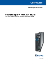
a. Connect the fiber between the Tx port on the transmitter and the Rx port on the receiver.
b. If you want the receiver to send return serial data (such as responses from a controlled device)
to the transmitter, connect a cable between the receiver’s Tx and transmitter’s Rx ports.
c. If you want a receiver to daisy chain the optical signal to another receiver (up to 10 receivers in
a daisy chain):
Connect the receiver’s Tx fiber cable to Rx on another receiver.
Set each receiver to daisy chain mode. See Normal and Daisy Chain Modes, below.
From Transmitter
or Daisy-Chained
Receiver
Receiver
Receiver
Tx Rx
Tx Rx
3a
3c
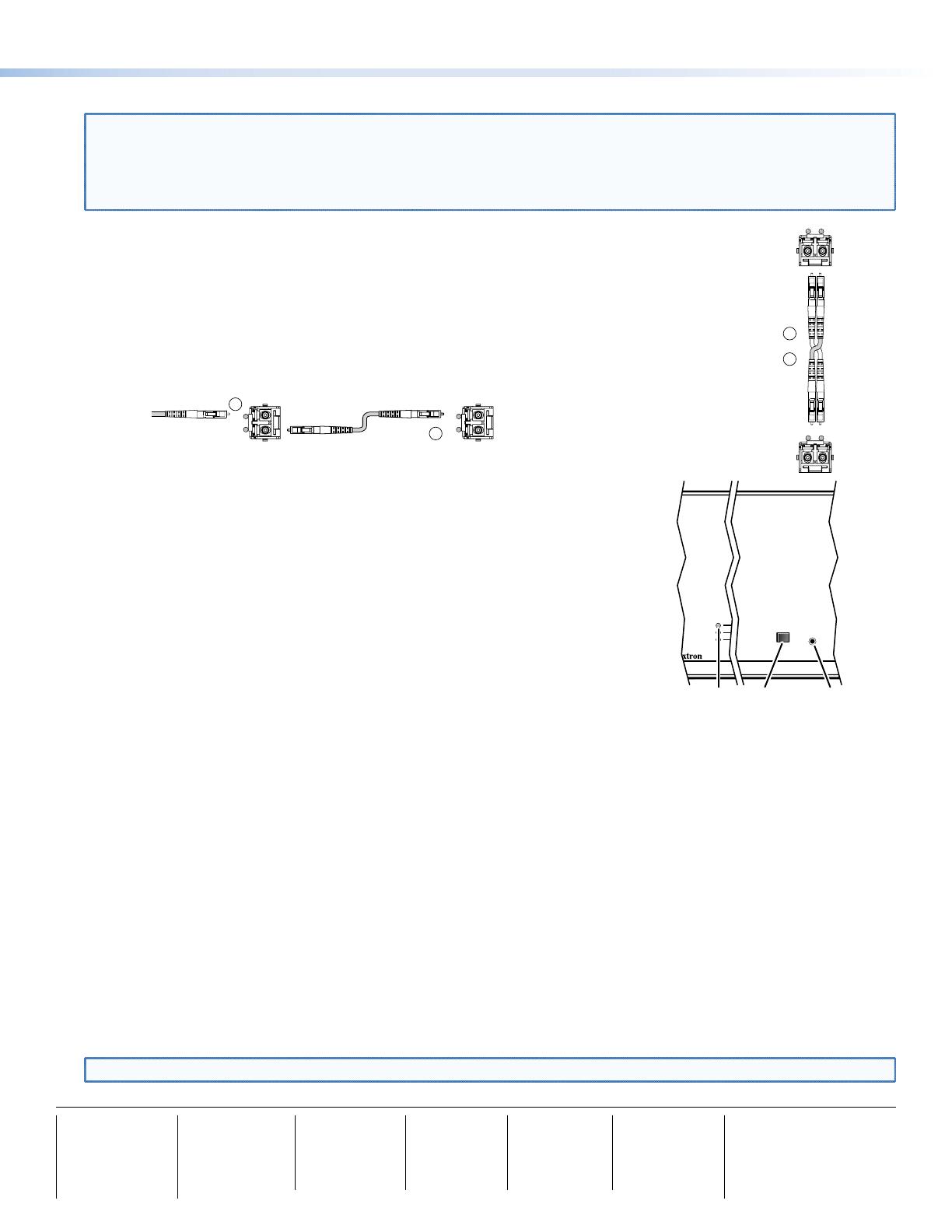
Step 4 — PowerCage Configuration Port
If desired, connect a host device to PowerCage enclosure Configuration connector via
the 9-pin D to 2.5 mm mini jack TRS RS-232 cable that is included with the PowerCage
enclosure or available separately using part #70-335-01. Repeatedly press the Comm
Select button until the Comm LED lights for the slot where the transmitter or receiver is
installed. The protocol for this port is as follows:
9600 baud no parity 8 data bits
1 stop bit no flow control
Refer to the PowerCage FOX 4G Tx/Rx User Guide for detailed information about using
the SIS commands and the Windows
®
-based FOX Extender program to set up and
operate the transmitter and receiver and to take advantage of the various adjustments
and test patterns available on the PowerCage FOX 4G units.
Operation
After all receivers, the transmitter, and their connected devices are powered up, the system is fully operational. If any
problems are encountered, verify that the cables are routed and connected properly and that all display devices have
identical resolutions and refresh rates. If your problems persist, call the Extron S
3
Sales & Technical Support Hotline at the
number shown below that is closest to you.
Normal and Daisy Chain Modes
The receiver operates on one of two modes:
Normal mode — The receiver outputs RS-232 and SIS commands and responses on its Tx LC connector.
Daisy chain mode — The receiver daisy chains its Rx connector input through to its Tx connector output.
Use SIS commands issued to the connected unit to toggle between normal and daisy chain modes. Connect a PC to the
Remote RS-232 port of either unit or to the Configuration port on the PowerCage enclosure and issue the following command:
66*0*n#
where:
n = 2 = enable daisy chain mode
n = 1 or 0 = disable daisy chain mode
NOTE: Up to 10 receivers, each in daisy chain mode, can be connected in a daisy chain to a single transmitter.
Receiver
Transmitter
Tx Rx
Tx Rx
and
3a
3b
COMM
1
POWER
ALARM
COMM
SELECT
CONFIG
Comm
Select
Button
Configuration
Port
Comm
LED
68-1911-50
Rev A
05 10
Extron USA - West
Headquarters
+800.633.9876
Inside USA / Canada Only
+1.714.491.1500
+1.714.491.1517 FAX
Extron USA - East
+800.633.9876
Inside USA / Canada Only
+1.919.863.1794
+1.919.863.1797 FAX
Extron Europe
+800.3987.6673
Inside Europe Only
+31.33.453.4040
+31.33.453.4050 FAX
Extron Asia
+800.7339.8766
Inside Asia Only
+65.6383.4400
+65.6383.4664 FAX
Extron Japan
+81.3.3511.7655
+81.3.3511.7656 FAX
Extron China
+400.883.1568
Inside China Only
+86.21.3760.1568
+86.21.3760.1566 FAX
Extron Middle East
+971.4.2991800
+971.4.2991880 FAX
© 2010 Extron Electronics. All rights reserved. www.extron.com
2
PowerCage FOX 4G Tx/Rx DVI and VGA Setup Guide (Continued)
  • Page 1 1
  • Page 2 2

Extron 4G TX/RX User manual

Category
Receiver
Type
User manual

Ask a question and I''ll find the answer in the document

Finding information in a document is now easier with AI