Page is loading ...

Crestron Green Light™
DIN-IO8
DIN Rail Versiport Module
Operations & Installation Guide

This document was prepared and written by the Technical Documentation department at:
Crestron Electronics, Inc.
15 Volvo Drive
Rockleigh, NJ 07647
1-888-CRESTRON
All brand names, product names and trademarks are the property of their respective owners.
©2008 Crestron Electronics, Inc.

Crestron DIN-IO8 DIN Rail Versiport Module
Contents
Crestron Green Light™ DIN Rail Versiport Module: DIN-IO8 1
Introduction ...............................................................................................................................1
Features and Functions................................................................................................1
Applications.................................................................................................................3
Specifications ..............................................................................................................4
Physical Description....................................................................................................5
Industry Compliance ...................................................................................................9
Setup........................................................................................................................................10
Network Wiring.........................................................................................................10
Identity Code.............................................................................................................10
Installation.................................................................................................................11
Hardware Hookup .....................................................................................................13
Programming Software............................................................................................................17
Earliest Version Software Requirements for the PC .................................................17
Programming with Crestron SystemBuilder..............................................................17
Programming with D3 Pro.........................................................................................18
Programming with SIMPL Windows........................................................................18
Example Program......................................................................................................20
Uploading and Upgrading........................................................................................................21
Establishing Communication.....................................................................................21
Programs and Firmware ............................................................................................22
Program Checks ........................................................................................................22
Operation.................................................................................................................................23
Problem Solving......................................................................................................................24
Troubleshooting.........................................................................................................24
Check Network Wiring..............................................................................................25
Reference Documents................................................................................................26
Further Inquiries........................................................................................................27
Future Updates ..........................................................................................................27
Return and Warranty Policies..................................................................................................28
Merchandise Returns / Repair Service ......................................................................28
CRESTRON Limited Warranty.................................................................................28
Operations & Installation Guide – DOC. 6664A Contents • i


Crestron DIN-IO8 DIN Rail Versiport Module
Crestron Green Light™ DIN Rail
Versiport Module: DIN-IO8
Introduction
The DIN-IO8 is a DIN rail-mounted automation control module that
provides eight Versiport I/O ports for interfacing with a wide range of
third-party devices and systems. Each “Versiport” can be configured via
software to function as a digital or analog sensing input, or as a digital
trigger output.
Features and Functions
• Eight Versiport I/O ports
• Interface for third-party sensors, detectors, contact closures,
and alarms
• Fully programmable functionality via DIN-AP2 or other
2-Series control system
• Cresnet
®
communications
• 6M wide DIN rail mounting
Versiports
Configured as a digital input, the Versiport will sense a contact closure or
logic level signal from devices such as motion detectors, partition
sensors, alarm panels, 12V triggers, and all types of switches and relays.
As an analog input, the Versiport can sense changes in a resistance or DC
voltage level, working with everything from temperature and light
sensors to water level meters to volume control potentiometers. As a
Operations & Installation Guide – DOC. 6664A DIN Rail Versiport Module: DIN-IO8 • 1

DIN Rail Versiport Module Crestron DIN-IO8
digital output, the Versiport provides a logic level closure signal to
trigger control and alarm inputs on a variety of external devices.
DIN Rail Installation
The DIN-IO8 is designed to snap onto a standard DIN rail for installation
in a wall mount enclosure or mounted on a wall panel. Wiring
connections are made using detachable screw terminals positioned along
the top and bottom, clearly accessible from the front for easy installation
and servicing. All setup controls and indicators are positioned on the
center front panel. When installed in an enclosure utilizing 45 mm
cutouts, the DIN-IO8’s front panel stays accessible while the connections
are concealed.
Cresnet
®
The DIN-IO8 communicates with a DIN-AP2 2-Series Automation
Processor, or other Crestron
®
2-Series control system, via the Cresnet
control network. Cresnet also powers the DIN-IO8. A pair of Cresnet
ports is provided on the DIN-IO8 allowing for easy daisy-chaining of
several DIN Rail Series automation control modules.
2 • DIN Rail Versiport Module: DIN-IO8 Operations & Installation Guide – DOC. 6664A

Crestron DIN-IO8 DIN Rail Versiport Module
Applications
The following diagram shows a DIN-IO8 in a commercial application.
DIN-IO8 in a Commercial Application
Operations & Installation Guide – DOC. 6664A DIN Rail Versiport Module: DIN-IO8 • 3

DIN Rail Versiport Module Crestron DIN-IO8
Specifications
Specifications for the DIN-IO8 are listed in the following table.
DIN-IO8 Specifications
SPECIFICATION DETAILS
Power Requirements
Cresnet Power Usage
1.5 Watts
(0.06 Amps @ 24 Volts DC)
Default NET ID 84
Minimum 2-Series Control
System Update File
1, 2
Version 4. 000.0226 or later
Environmental
Temperature
Humidity
Heat Dissipation
0° to 40°C (32° to 104°F)
10% to 90% RH (non-condensing)
5 BTU/Hr
Enclosure Light gray polycarbonate housing
with polycarbonate label overlay,
UL94 V-0 rated, 35 mm DIN EN
60715 rail mount, DIN 43880 form
factor for enclosures with 45 mm
front panel cutout, occupies 6 DIN
module spaces (108 mm)
Dimensions
Height
Width
Depth
94.2 mm (3.71 in)
106 mm (4.17 in)
59.5 mm (2.34 in)
Weight 165 g (6 oz)
(Continued on following page)
4 • DIN Rail Versiport Module: DIN-IO8 Operations & Installation Guide – DOC. 6664A

Crestron DIN-IO8 DIN Rail Versiport Module
DIN-IO8 Specifications (Continued)
SPECIFICATION DETAILS
Available Accessories
DIN-BLOCK
DIN-HUB
DIN-PWS50
DIN Rail Cresnet Distribution
Block
DIN Rail Cresnet Distribution Hub
DIN Rail 50 Watt Cresnet Power
Supply
1. The latest software versions can be obtained from the Crestron website. Refer to
the NOTE following these footnotes.
2. Crestron 2-Series control systems include the AV2 and PRO2. Consult the latest
Crestron Product Catalog for a complete list of 2-Series control systems.
NOTE: Crestron software and any files on the website are for authorized
Crestron dealers and Crestron Authorized Independent Programmers
(CAIP) only. New users may be required to register to obtain access to
certain areas of the site (including the FTP site).
Physical Description
This section provides information on the connections, controls and
indicators available on your DIN-IO8.
DIN-IO8 Physical View
Operations & Installation Guide – DOC. 6664A DIN Rail Versiport Module: DIN-IO8 • 5

DIN Rail Versiport Module Crestron DIN-IO8
DIN-IO8 Overall Dimensions
94.2 mm
(3.71 in)
90 mm
(3.54 in)
106 mm
(4.17 in)
58 mm
(2.28 in)
59.5 mm
(2.34 in)
1
3
2
4 5 6 7
Connectors, Controls & Indicators
# CONNECTORS*,
CONTROLS &
INDICATORS
DESCRIPTION
1 I/O 1-8 and LEDs (2) 5-pin 3.5 mm detachable
terminal blocks comprising (8)
digital input/output or analog
input ports (referenced to
GND);
Max Wire Size: 1.5 mm
2
(16 AWG)
Digital Input:
Rating: 0-24 Volts DC
Input Impedance: 20k ohms
Logic Threshold: 1.25 Volts
DC
(Continued on following page)
6 • DIN Rail Versiport Module: DIN-IO8 Operations & Installation Guide – DOC. 6664A

Crestron DIN-IO8 DIN Rail Versiport Module
Connectors, Controls & Indicators (Continued)
# CONNECTORS*,
CONTROLS &
INDICATORS
DESCRIPTION
1 I/O 1-8 and LEDs
(continued)
Analog Input:
Rating: 0-10 Volts DC,
protected to 24 Volts DC
maximum
Input Impedance: 20k ohms
Digital Output: 250 mA sink
from maximum 24 Volts DC,
catch diodes for use with “real
world” loads
Programmable 5 Volts, 2k
ohms pull-up resistor per input
(8) Red LEDs, indicate status of
each respective I/O Versiport
2 NET ID DISPLAY &
CONTROL
(2) 7-Segment green LED digits
and (2) miniature pushbuttons
for setting Net ID and indicating
errors
3 NET (2) 4-pin 3.5mm detachable
terminal blocks, paralleled
Cresnet slave port
Max Wire Size: 1.5 mm
2
(16 AWG)
Pin 1 (24): Power (24 VDC)
Pin 2 (Y): Data
Pin 3 (Z): Data
Pin 4 (G): Ground
(Continued on following page)
Operations & Installation Guide – DOC. 6664A DIN Rail Versiport Module: DIN-IO8 • 7

DIN Rail Versiport Module Crestron DIN-IO8
Connectors, Controls & Indicators (Continued)
# CONNECTORS*,
CONTROLS &
INDICATORS
DESCRIPTION
4 SETUP
(LED and button)
(1) Red LED and (1) recessed
miniature pushbutton for
enabling setup mode and
touch-settable ID
5 PWR (1) Green LED, illuminates
when DC power is applied to
the NET port
6 RESET (1) Recessed miniature
pushbutton, resets internal
processor
7 NET (1) Yellow LED, indicates
communication with the control
processor
* Interface connectors for NET and I/O ports are provided with the unit.
8 • DIN Rail Versiport Module: DIN-IO8 Operations & Installation Guide – DOC. 6664A

Crestron DIN-IO8 DIN Rail Versiport Module
Industry Compliance
This unit has been manufactured to comply with UL’s Standards for
Safety in Canada and the United States. Formal approval is pending.
As of the date of manufacture, the DIN-IO8 has been tested and found to
comply with specifications for CE marking and standards per EMC and
Radiocommunications Compliance Labelling.
NOTE: This device complies with part 15 of the FCC rules. Operation is
subject to the following two conditions: (1) this device may not cause
harmful interference and (2) this device must accept any interference
received, including interference that may cause undesired operation.
This equipment has been tested and found to comply with the limits for a
Class B digital device, pursuant to part 15 of the FCC Rules. These limits
are designed to provide reasonable protection against harmful
interference in a residential installation. This equipment generates, uses
and can radiate radio frequency energy and if not installed and used in
accordance with the instructions, may cause harmful interference to radio
communications. However, there is no guarantee that interference will
not occur in a particular installation. If this equipment does cause harmful
interference to radio or television reception, which can be determined by
turning the equipment off and on, the user is encouraged to try to correct
the interference by one or more of the following measures:
Reorient or relocate the receiving antenna.
Increase the separation between the equipment and receiver.
Connect the equipment into an outlet on a circuit different from
that to which the receiver is connected.
Consult the dealer or an experienced radio/TV technician for help.
Operations & Installation Guide – DOC. 6664A DIN Rail Versiport Module: DIN-IO8 • 9

DIN Rail Versiport Module Crestron DIN-IO8
Setup
Network Wiring
When wiring the Cresnet network, consider the following:
• Use Crestron Certified Wire.
NOTE: Cresnet-HP wire cannot be used.
• Use Crestron power supplies for Crestron equipment.
• Provide sufficient power to the system.
CAUTION: Insufficient power can lead to unpredictable results
or damage to the equipment. Please use the Crestron Power
Calculator to help calculate how much power is needed for the
system (
www.crestron.com/calculators).
• Use of a Cresnet hub/repeater (DIN-HUB) is advised whenever the
number of Cresnet devices on a network exceeds 20, or when the
combined total length of Cresnet cable exceeds 914 meters (3000
feet).
For more details, refer to “
Check Network Wiring” on page 25.
Identity Code
The Net ID of the DIN-IO8 has been factory set to 84. The Net IDs of
multiple DIN-IO8 devices in the same system must be unique. Net IDs
are changed on the front panel of the DIN-IO8 or from a personal
computer (PC) via Crestron Toolbox™ (refer to “
Establishing
Communication
” on page 21).
To set the Net ID using the front panel:
• Press the SETUP button to enter the Setup mode. The SETUP
LED illuminates.
• Press the left button under the NET ID display to change the most
significant digit of the Net ID or press the right button under the
NET ID display to change the least significant digit of the Net ID
number.
10 • DIN Rail Versiport Module: DIN-IO8 Operations & Installation Guide – DOC. 6664A

Crestron DIN-IO8 DIN Rail Versiport Module
• When the desired Net ID is displayed, press the SETUP button to
exit the Setup mode. The SETUP LED extinguishes.
NOTE: If an invalid Net ID is set (00, 02, FF), “Er” will be
displayed on the NET ID display. The DIN-IO8 reverts to the
previously set Net ID.
NOTE: The DIN-IO8 will leave the Setup mode after 10 seconds
of inactivity. The DIN-IO8 will revert to the previously set Net ID.
NOTE: A small label (with numbers and letters) is provided on
the front panel of the DIN-IO8 to document the unit’s Net ID in
the case where power is not available. Apply a mark over the digits
that correspond to the assigned Net ID.
NET ID Label (“3C” Shown)
When setting the Net ID, consider the following:
• The Net ID of each unit must match an ID code specified in the
SIMPL™ Windows
®
program.
• Each network device must have a unique Net ID.
For more details, refer to the Crestron Toolbox help file.
Installation
The DIN-IO8 must be installed by a licensed electrician, in accordance
with all national and local codes.
CAUTION: This equipment is for indoor use only. Mount in a well
ventilated area. The ambient temperature must be 0º to 40º C
(32º to 104º F). The relative humidity must be 10% – 90%
(non-condensing).
Operations & Installation Guide – DOC. 6664A DIN Rail Versiport Module: DIN-IO8 • 11

DIN Rail Versiport Module Crestron DIN-IO8
The DIN-IO8 is designed for installation on a DIN rail. Refer to the
following diagram when installing.
Installing the DIN-IO8
DIN RAIL RELEASE
TOP
DIN RAIL
(NOT SUPPLIED)
DIN-IO8
1. Place the top of the DIN-IO8’s rail mount over the top of the DIN
rail.
2. Tilt the bottom of the DIN-IO8 toward the DIN rail until it snaps
into place.
NOTE: When mounting DIN rail products, it may be necessary to
use a flat-head screw driver to pull the DIN rail release tab while
snapping the device onto the DIN rail.
To remove the DIN-IO8 from the DIN rail, use a small, flat object (i.e. a
flat-head screwdriver) to pull the DIN rail release tab and tilt the bottom
of the DIN-IO8 away from the DIN rail.
NOTE: Certain third party DIN cabinets provide space for an
informational label between each DIN rail row. Crestron’s Engraver
software (version 4.0 or later) can generate appropriate labels for all
Crestron DIN rail products.
12 • DIN Rail Versiport Module: DIN-IO8 Operations & Installation Guide – DOC. 6664A

Crestron DIN-IO8 DIN Rail Versiport Module
Hardware Hookup
Connect the
Device
Make the necessary connections as called out in the illustration that
follows this paragraph. Refer to “
Network Wiring” on page 10 before
attaching the 4-position terminal block connector. Apply power after all
connections have been made.
WARNING: Prior to connecting the device, turn off power at the circuit
breaker. Failure to do so may result in serious personal injury or damage
to the device. Restore power after all connections have been made.
CAUTION: Connecting this device to the wrong type of load, or short-
circuiting the load can cause severe product damage. Each load should be
tested to identify a short circuit condition prior to wiring the load to the
module.
NOTE: Install in accordance with all local and national electric codes.
NOTE: Use copper wire only.
When making network connections to the DIN-IO8, use a Crestron
power supply.
Operations & Installation Guide – DOC. 6664A DIN Rail Versiport Module: DIN-IO8 • 13

DIN Rail Versiport Module Crestron DIN-IO8
Hardware Connections for the DIN-IO8
NET:
TO CONTROL SYSTEM AND
OTHER CRESNET DEVICES
I/O:
TO / FROM DEVICES
14 • DIN Rail Versiport Module: DIN-IO8 Operations & Installation Guide – DOC. 6664A

Crestron DIN-IO8 DIN Rail Versiport Module
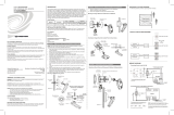
Versiport
Connections
Depending on the application, the DIN-IO8’s Versiports can be wired
multiple ways. Refer to the following diagrams when wiring a Versiport.
WARNING: Incorrect wiring may damage the DIN-IO8.
NOTE: The settings for input/output and the pull-up resistor are
specified in the control system program. For more information, refer to
the SIMPL Windows help file.
Versiport Wiring Diagrams—Digital Input Function
I/O Setup:
Digital Input
Pull-up Resistor:
Enabled
Detecting a contact
closure from a switch
or relay
I/O Setup:
Digital Input
Pull-up Resistor:
Disabled
Detecting a
voltage from a
switch or relay
24V DC Max.
Operations & Installation Guide – DOC. 6664A DIN Rail Versiport Module: DIN-IO8 • 15

DIN Rail Versiport Module Crestron DIN-IO8
Versiport Wiring Diagrams—Analog Input Function
I/O Setup:
Analog Input
Pull-up Resistor:
Disabled
Reading a voltage
from an analog
source
I/O Setup:
Analog Input
Pull-up Resistor:
Enabled
Reading
resistance of a
potentiometer
10V DC
Versiport Wiring Diagrams—Digital Output Function
I/O Setup:
Digital Output
Pull-up Resistor:
Disabled
Driving a relay
coil
24V DC
Max.
16 • DIN Rail Versiport Module: DIN-IO8 Operations & Installation Guide – DOC. 6664A
/