Gigabyte GA-7VT880-L User manual

Category
Motherboards
Type
User manual

This manual is also suitable for

When you installing AGP card, please make sure the following notice
is fully understood and practiced. If your AGP card has "AGP 4X/8X
(1.5V) notch"(show below), please make sure your AGP card is AGP
4X/8X.
Caution: AGP 2X card is not supported by VIA KT880. You might
experience system unable to boot up normally. Please insert an AGP
4X/8X card.
Example 1: Diamond Vipper V770 golden finger is compatible with 2X/4X
mode AGP slot. It can be switched between AGP 2X(3.3V) or 4X(1.5V) mode
by adjusting the jumper. The factory default for this card is 2X(3.3V). The
GA-7VT880 Pro / GA-7VT880-L / GA-7VT880 (or any AGP 4X/8X only)
motherboards might not function properly, if you install this card without
switching the jumper to 4X(1.5V) mode in it.
Example 2: Some ATi Rage 128 Pro graphics cards made by "Power Color",
the graphics card manufacturer & some SiS 305 cards, their golden finger is
compatible with 2X(3.3V) / 4X(1.5V) mode AGP slot, but they support
2X(3.3V) only. The GA-7VT880 Pro / GA-7VT880-L / GA-7VT880 (or any
AGP 4X/8X only) motherboards might not function properly, If you install this
card in it.
Note : Although Gigabyte's AG32S(G) graphics card is based on ATi Rage
128 Pro chip, the design of AG32S(G) is compliance with AGP 4X(1.5V)
specification. Therefore, AG32S(G) will work fine with VIA KT880 based
motherboards.
Before you install PCI cards, please remove the Dual BIOS label from PCI
slots if there is one.
AGP 4X/8X notch
The author assumes no responsibility for any errors or
omissions that may appear in this document nor does the
author make a commitment to update the information
contained herein.
Third-party brands and names are the property of their
respective owners.
Please do not remove any labels on motherboard, this may
void the warranty of this motherboard.
Due to rapid change in technology, some of the
specifications might be out of date before publication of
this booklet.
Mother Board
GA-7VT880 Pro / GA-7VT880-L / GA-7VT880
May 13, 2004
FCC Part 15, Subpart B, Section 15.107(a) and Section 15.109(a),
Class B Digital Device
DECLARATION OF CONFORMITY
Per FCC Part 2 Section 2.1077(a)
Responsible Party Name:
Address:
Phone/Fax No:
hereby declares that the product
Product Name: Motherboard
Conforms to the following specifications:
This device complies with part 15 of the FCC Rules. Operation is
subject to the following two conditions: (1) This device may not
cause harmful and (2) this device must accept any inference received,
including that may cause undesired operation.
Representative Person’s Name:
Signature:
Eric Lu
Supplementary Information:
Model Number:
17358 Railroad Street
City of Industry, CA 91748
G.B.T. INC. (U.S.A.)
(818) 854-9338/ (818) 854-9339
Date:
ERIC LU
May 13, 2004
GA-7VT880 Pro /GA-7VT880-L /GA-7VT880
USER'S MANUAL
GA-7VT880 Series
AMD Socket A Processor Motherboard
AMD Athlon
/ Athlon
XP / Duron
Socket A Processor Motherboard
Rev. 1002
12ME-7VT880-1002
- 2 -GA-7VT880 Serie Motherboard
English
Table of Content
Warning.................................................................................................. 4
Chapter 1 Introduction........................................................................... 5
Features Summary ..................................................................................... 5
GA-7VT880 Series Motherboard Layout ....................................................7
Block Diagram - GA-7VT880 Series .......................................................... 8
Chapter 2 Hardware Installation Process.............................................. 9
Step 1: Set System Jumper (SW1).............................................................. 9
Step 2: Install the Central Processing Unit (CPU) ....................................10
Step 2-1: CPU Installation..............................................................................................10
Step 2-2: CPU Cooling Fan Installation........................................................................ 11
Step 3: Install Memory Modules ...............................................................12
Step 4: Install expansion cards.................................................................13
Step 5: Connect ribbon cables, cabinet wires and power supply ............14
Step 5-1: I/O Back Panel Introduction...........................................................................14
Step 5-2: Connectors Introduction .................................................................................16
Chapter 3 BIOS Setup ........................................................................ 31
The Main Menu (For example: BIOS Ver. : E9) .......................................32
Standard CMOS Features........................................................................34
Advanced BIOS Features ......................................................................... 36
Integrated Peripherals..............................................................................37
Table of Content
English
- 3 -
Power Management Setup.......................................................................40
PnP/PCI Configurations ............................................................................41
PC Health Status.......................................................................................42
MB Intelligent Tweaker (M.I.T) .................................................................43
Load Fail-Safe Defaults ............................................................................45
Load Optimized Defaults ..........................................................................45
Set Supervisor/User Password ................................................................. 46
Save & Exit Setup......................................................................................47
Exit Without Saving...................................................................................47
Chapter 4 Technical Reference........................................................... 49
@BIOS
Introduction ................................................................................49
Flash BIOS Method Introduction ..............................................................50
2- / 4- / 6-Channel Audio Function Introuction..........................................57
Jack-Sensing and UAJ Introduction ......................................................... 63
Xpress Recovery Introduction...................................................................67
Serial ATA RAID BIOS Utility Introduction..................................................71
Chapter 5 Appendix............................................................................ 79
- 4 -GA-7VT880 Serie Motherboard
English
Warning
Computer motherboards and expansion cards contain very delicate Integrated Circuit
(IC) chips. To protect them against damage from static electricity, you should follow
some precautions whenever you work on your computer.
1. Unplug your computer when working on the inside.
2. Use a grounded wrist strap before handling computer components. If you do not have one, touch
both of your hands to a safely grounded object or to a metal object, such as the power supply
case.
3. Hold components by the edges and try not touch the IC chips, leads or connectors, or other
components.
4. Place components on a grounded antistatic pad or on the bag that came with the components
whenever the components are separated from the system.
5. Ensure that the ATX power supply is switched off before you plug in or remove the ATX power
connector on the motherboard.
Installing the motherboard to the chassis...
If the motherboard has mounting holes, but they don't line up with the holes on the base and there are
no slots to attach the spacers, do not become alarmed you can still attach the spacers to the mounting
holes. Just cut the bottom portion of the spacers (the spacer may be a little hard to cut off, so be careful of
your hands). In this way you can still attach the motherboard to the base without worrying about short
circuits. Sometimes you may need to use the plastic springs to isolate the screw from the motherboard
PCB surface, because the circuit wire may be near by the hole. Be careful, don't let the screw contact
any printed circuit write or parts on the PCB that are near the fixing hole, otherwise it may damage the
board or cause board malfunctioning.
Introduction
English
- 5 -
to be continued......
Chapter 1 Introduction
Features Summary
1 Only for GA-7VT880 Pro. 2 Only for GA-7VT880-L.
Motherboard GA-7VT880 Series:
GA-7VT880 Pro / GA-7VT880-L / GA-7VT880
CPU Socket A processor
AMD Athlon
TM
/ Athlon
TM
XP/ Duron
TM
(K7)
128K L1 & 512K/256K/64K L2 cache on die
200/266/333/400
MHz FSB
Supports 1.4GHz and faster
Chipset VIA KT880 Memory/AGP Controller (PAC)
VIA VT8237 Integrated Peripheral Controller (PSIPC)
Memory 4 184-pin DDR sockets,supports up to 4.0GB DDR (Max)
(Note 1)
Supports Dual Channel DDR400/DDR333/DDR266
Supports 128MB/256MB/512MB/1GB unbuffered DRAM
Supports only 2.5V DDR DIMM
Slots 1 AGP slot supports 8X/4X mode(1.5V) & AGP 3.0 compliant
5 PCI slots supports 33MHz & PCI 2.2 compliant
On-Board IDE 2 IDE controllers provides IDE HDD/CD-ROM (IDE1, IDE2)
with PIO, Bus Master (Ultra DMA33/ATA66/ATA100/ATA133)
operation mode
On-Board Floppy 1 Floppy port supports 2 FDD with 360K, 720K,1.2M, 1.44M and
2.88M bytes
On-Board SATA
(Note2)
2 Serial ATA connectors
2 SATA connectors controlled by VIA VT8237(SATA0,SATA1)
On-Board Peripherals 1 Parallel port supports Normal/EPP/ECP mode
2 Serial ports (COMA & COMB)
3 x IEEE1394 ports (by cable)
8 x USB 2.0/1.1 (rearx4, frontx4 by cable)
1 Front Audio connector
1 IrDA connector for IR
1 PS/2 keyboard
1 PS/2 mouse
On-Board LAN Built-in RTL8110S (10/100/1000 Mbit)(1)
Built-in RTL8100C (10/100 Mbit)(2)
1 RJ45 ports
(Note 1) Due to standard PC architecture, a certain amount of memory is reserved for system usage and therefore the
actual memory size is less than the stated amount.For example, 4 GB of memory size will instead be shown as 3.
xxGB memory during ystem startup.
(Note 2) It is recommended to use SATA (1.5Gb/s) hard disks.
- 6 -GA-7VT880 Serie Motherboard
English
On-Board Sound Realtek ALC658 CODEC(UAJ)
Supports Jack Sensing function
Supports 2-/4-/6-channel
Line Out / Line In / Mic In
SPDIF Out /SPDIF In
CD In / AUX In / Game connector
On-Board IEEE1394 Built-in VIA VT6306
On-Board SATA RAID Built-in VIA VT8237
(SATA0, SATA1) Supports disk striping (RAID 0) or disk mirroring (RAID 1)
Supports up to 150MB/s data transfer rate
Up to 2 SATA devices
I/O Control IT8705F
Hardware Monitor CPU/System Fan Revolution detect
CPU temperature detect
System voltage detect
CPU/System fan fail warning
Thermal shutdown function
BIOS Licensed Award BIOS
Supports Q-Flash / Dual BIOS j
Additional Features Supports @BIOS
Supports EasyTune
Overclocking Over Voltage (CPU/AGP/DDR/PCI) by BIOS
Over Clock (CPU/AGP/DDR/PCI) by BIOS
Form Factor 30.5cm x 24.4cm ATX size form factor, 4 layers PCB.
Please set the CPU host frequency in accordance with your processor's specifications.
We don't recommend you to set the system bus frequency over the CPU's specification
because these specific bus frequencies are not the standard specifications for CPU,
chipset and most of the peripherals. Whether your system can run under these specific
bus frequencies properly will depend on your hardware configurations, including CPU,
Chipsets, SDRAM, Cards etc.
j Only for GA-7VT880 Pro.
Introduction
English
- 7 -
GA-7VT880 Series Motherboard Layout
j Only for GA-7VT880 Pro. k Only for GA-7VT880-L.
GA-7VT880 Pro
KB_MS
COMA
LPT
IT8705F
CODEC
BATTERY
Backup
BIOSj
VT8237
VIA KT880
SOCKET A
CPU_FAN
ATX
FDD
IDE1
PCI1
PCI2
PCI3
PCI4
DDR1
AGP
F_USB1
COMB
CD_IN
PCI5
DDR2
F_AUDIO
IR
F_PANEL
F_USB2
AUX_IN
SUR_CEN
SPDIF_IO
PWR_LED
GAME
AUDIO
USB
LANjk
-Lk
IDE2
VT6306
SW1
SATA0
SATA1
USB
DDR3
DDR4
Main
BIOS
PWR_FANj
ATX_12V
F1_1394
F2_1394
INFO_LINK
RLT8110Sj
RLT8100Ck
CLR_CMOS
RAM_LED
SYS_FAN
CI
- 8 -GA-7VT880 Serie Motherboard
English
Block Diagram
j Only for GA-7VT880 Pro. k Only for GA-7VT880-L.
33 MHz
14.318 MHz
AGP
4X/8X
AGPCLK
(66MHz)
5 PCI
PCICLK
(33MHz)
AC97 Link
MIC
LINE-IN
LINE-OUT
AC97
CODEC
2 Serial ATA
VIA VT8237
LPC BUS
8 USB
Ports
IT8705F
24 MHz
33 MHz
Game Port
Floppy
LPT Port
2 COM Ports
3 IEEE1394
VT6306
IR
ATA33/66/100/133
IDE Channels
Dual Channel DDR
PS/2 KB/Mouse
RJ45jk
RTL8110Sj
RTL8100Ck
VIA KT880
AMD-K7
TM
CPUCLK+/- (100/133/166/200MHz)
System Bus
100/133/166/200MHz
Dual
BIOSj
Hardware Installation Process
English
- 9 -
To set up your computer, you must complete the following steps:
Step 1- Set system jumper (SW1)
Step 2- Install the Central Processing Unit (CPU)
Step 3- Install memory modules
Step 4- Install expansion cards
Step 5- Connect ribbon cables, cabinet wires, and power supply
Chapter 2 Hardware Installation Process
Step 3
Step 1
Step 4
Step 5
Step 2
Step 5
Step 5
Step 1: Set System Jumper (SW1)
The system bus frequency can be switched at 100/133/166/200MHz by adjusting SW1.
SW1
You must set SW1 to "ON" when
you used FSB 200MHz CPU.
100MHz : Fix FSB 200MHz CPU
AUTO : Supports FSB 400/333/266 MHz CPU
ON
SW1
ON 100MHz
OFF AUTO
- 10 -GA-7VT880 Serie Motherboard
English
Before installing the processor, adhere to the following warning:
1.Please make sure the CPU type is supported by the motherboard.
2.If you do not match the CPU socket Pin 1 and CPU cut edge well, it will
cause improper installation. Please change the insert orientation.
CPU Top View CPU Bottom View
Socket Actuation Lever
1 Pull up the CPU socket lever and
up to 90-degree angle.
Pin1 indicator
2. Locate Pin 1 in the socket and look
for a (golden) cut edge on the CPU
upper corner. Then insert the CPU
into the socket.
Step 2: Install the Central Processing Unit (CPU)
Step 2-1: CPU Installation
Hardware Installation Process
English
- 11 -
Step 2-2: CPU Cooling Fan Installation
Before installing the CPU cooling fan, adhere to the following warning:
1.Please use AMD approved cooling fan.
2.We recommend you to apply the thermal tape to provide better heat
conduction between your CPU and cooling fan.
3.Make sure the CPU fan power cable is plugged in to the CPU fan
connector, this completes the installation.
Please refer to CPU cooling fan user's manual for more detail
installation procedure.
3. Fasten the cooling fan supporting-
base onto the CPU socket on the
motherboard.
2. Use qualified fan approved by AMD.
4. Make sure the CPU fan is plugged
to the CPU fan connector, than
install complete.
1. Press down the CPU socket lever
and finish CPU installation.
- 12 -GA-7VT880 Serie Motherboard
English
Step 3: Install Memory Modules
The motherboard has 4 dual inline memory module (DIMM) sockets. The BIOS will automatically
detects memory type and size. To install the memory module, just push it vertically into the DIMM
socket. The DIMM module can only fit in one direction due to the notch. Memory size can vary
between sockets.
DDR
Notch
1. The DIMM socket has a notch, so the DIMM
memory module can only fit in one direction.
2. Insert the DIMM memory module vertically into
the DIMM socket. Then push it down.
3. Close the plastic clip at both edges of the DIMM
sockets to lock the DIMM module.
Reverse the installation steps when you wish to
remove the DIMM module.
Before installing the memory modules, adhere to the following warning:
1.When RAM_LED is ON, do not install / remove DIMM from socket.
2.Please note that the DIMM module can only fit in one direction due to
the one notch. Wrong orientation will cause improper installation.
Please change the insert orientation.
Hardware Installation Process
English
- 13 -
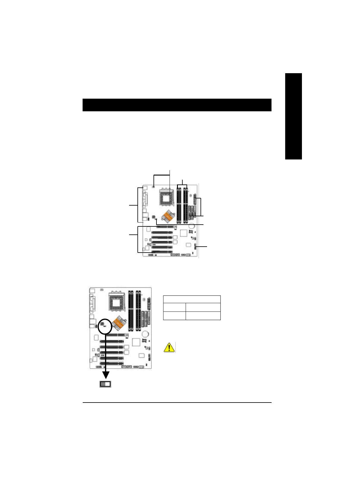
l Figure 1: Dual Channel Technology (DS: Double Side, SS: Single Side)
The following tables include all memory-installed combination types:
(Please note that this types not in the tables will not boot up.)
Below are the explanations:
If you want to operate the Dual Channel Technology, please note the following explanations due
to the limitation of VIA chipset specifications.
1. Only one DDR memory module is installed: The Dual Channel Technology can't operate
when only one DDR memory module is installed.
2. Two DDR memory modules are installed: The Dual Channel Technology will operate
when two memory modules are inserted individually into Channel A and B and must use
the same memory frequency & memory size. If you install two memory modules in the
same channel,the Dual Channel Technology will not operate.
Dual Channel DDR:
GA-7VT880 Pro / GA-7VT880-L / GA-7VT880 support Dual Channel Technology. When Dual Channel
Technology is activated, the bandwidth of memory bus will be double the original one, with the fastest
speed at 6.4GB/s(DDR400) .
GA-7VT880 Pro / GA-7VT880-L / GA-7VT880 include 4 DIMM slots, and each Channel has 2 DIMMs
as following: Channel A : DDR 1, 2
Channel B : DDR 3, 4
2 memory modules
4 memory modules
DDR 1 DDR 2 DDR 3 DDR 4
DS/SS X DS/SS X
X DS/SS X DS/SS
DS/SS DS/SS DS/SS DS/SS
Step 4: Install expansion cards
1. Read the related expansion card's instruction document before install the expansion card into the computer.
2. Remove your computer's chassis cover, screws and slot bracket from the computer.
3. Press the expansion card firmly into expansion slot in motherboard.
4. Be sure the metal contacts on the card are indeed seated in the slot.
5. Replace the screw to secure the slot bracket of the expansion card.
6. Replace your computer's chassis cover.
7. Power on the computer, if necessary, setup BIOS utility of expansion card from BIOS.
8. Install related driver from the operating system.
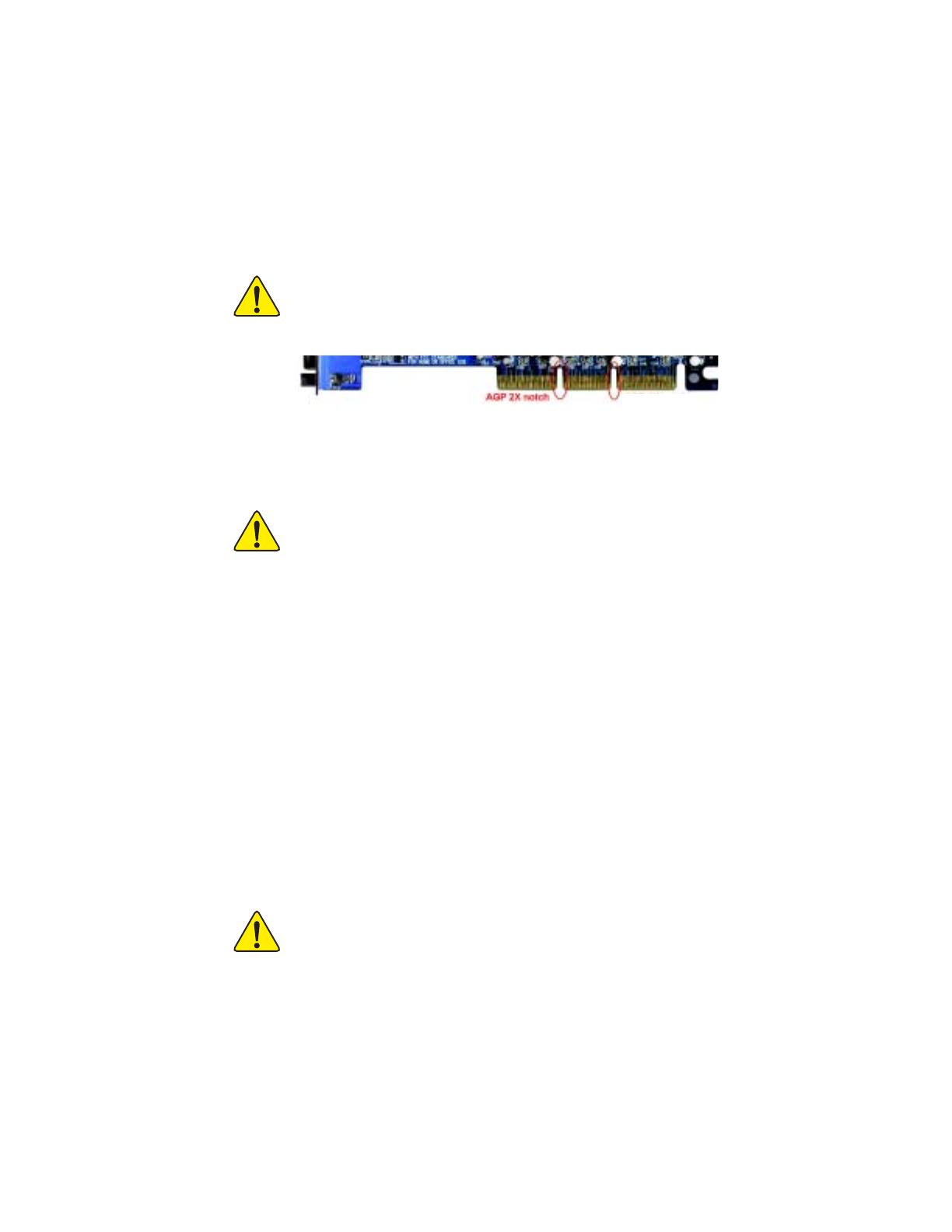
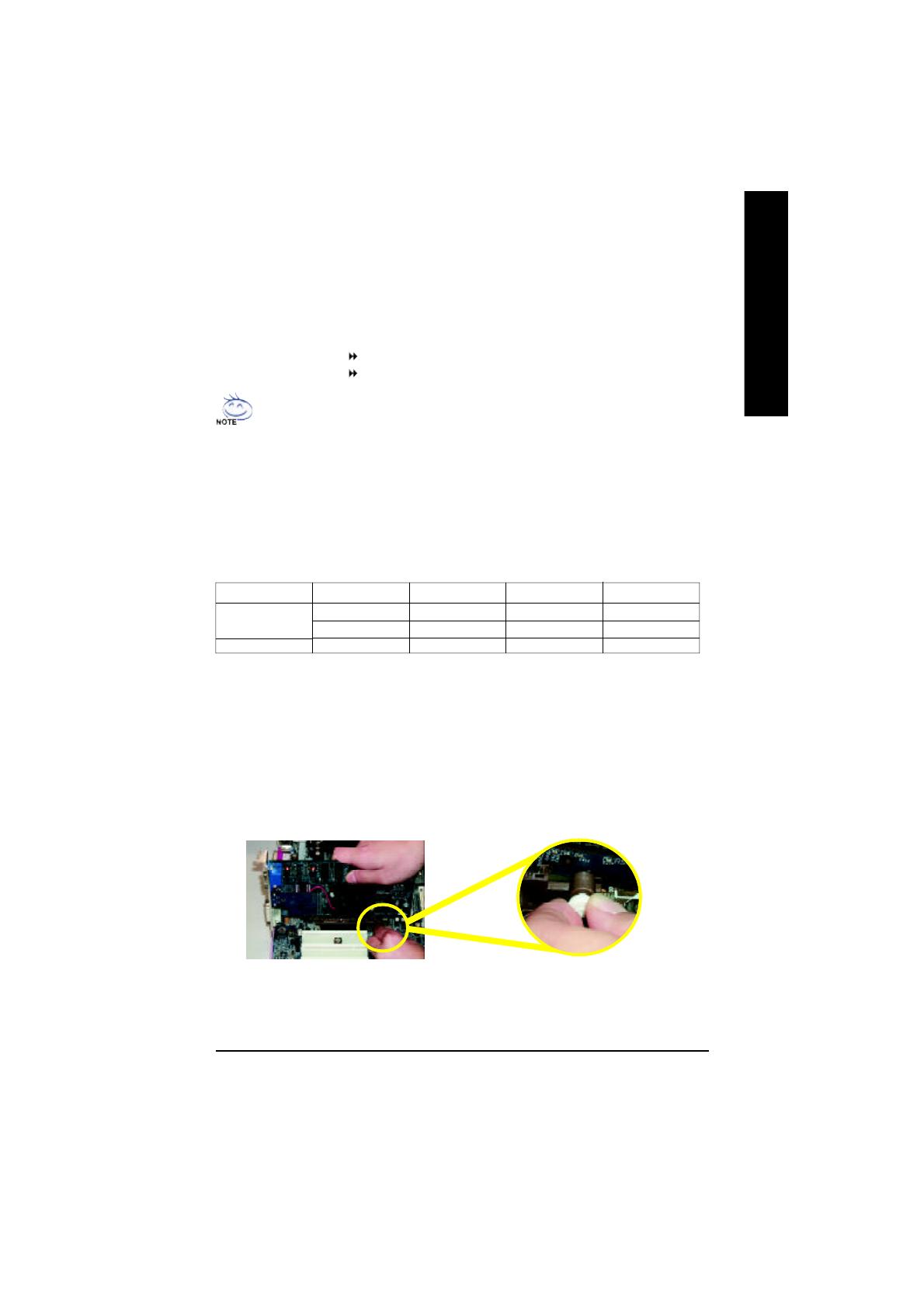
Please carefully pull out the small white-drawable bar at the end of the AGP slot when you try
to install / uninstall the AGP card. Please align the AGP card to the onboard AGP slot and
press firmly down on the slot. Make sure your AGP card is locked by the small white-
drawable bar.
- 14 -GA-7VT880 Serie Motherboard
English
Step 5: Connect ribbon cables, cabinet wires and power supply
Step 5-1: I/O Back Panel Introduction
This connector supports standard PS/2
keyboard and PS/2 mouse.
PS/2 Mouse Connector
(6 pin Female)
PS/2 Keyboard Connector
(6 pin Female)
PS/2 Keyboard and PS/2 Mouse Connector
This connector supports 2 standard COM ports
and 1 Parallel port. Devices like printer can be
connected to Parallel port; mouse and modem
etc. can be connected to Serial ports.
Parallel Port, Serial Ports (COMA / COMB)
Parallel Port (25 pin Female)
COMA COMB
Serial Port (9 pin Male)
Hardware Installation Process
English
- 15 -
Line In
MIC In
Line Out
After install onboard audio driver, you may con-
nect speaker to Line Out jack, microphone to MIC
In jack. Device like CD-ROM,walkman etc. can
be connected to Line-In jack.
Please note:
You are able to use 2-/4-/6-/8-channel audio
feature by S/W selection.
If you want to enable 8-channel function you can
refer to page 24, and contact your nearest dealer
for optional SUR_CEN cable.
If you want the detail information for 2-/4-/6-channel audio setup
installation, please refer to page 57.
Audio Connectors
j Only for GA-7VT880 Pro. k Only for GA-7VT880-L.
/ USB/LANjk Connector
Before you connect your device(s) into USB
connector(s), please make sure your device(s)
such as USB keyboard,mouse, scanner, zip,
speaker...etc. Have a standard USB interface.
Also make sure your OS supports USB
controller. If your OS does not support USB
controller, please contact OS vendor for
possible patch or driver upgrade. For more
information please contact your OS or device
(s) vendors.
USB 0
USB 1
USB 2
USB 3
LANjk
- 16 -GA-7VT880 Serie Motherboard
English
Step 5-2: Connectors Introduction
j Only for GA-7VT880 Pro.
1) ATX_12V
2) ATX
3) CPU_FAN
4) SYS_FAN
5) PWR_FAN
(
j
)
6) FDD
7) IDE1 / IDE2
8) SATA0 / SATA1
9) F_PANEL
10) BAT
11) PWR_LED
12) RAM_LED
13) F_AUDIO
14) SUR_CEN
15) SPDIF_IO
16) CD_IN
17) AUX_IN
18) F_USB1 / F_USB2
19) F1_1394 / F2_1394
20) IR
21) GAME
22) INFO_LINK
23) CLR_CMOS
24) CI
20
17
23
13
21
3
7
9
2
5
(
j
)
11
1
16
15
18
10
22
12
4
6
14
8
19
(
j
)
24
1 / 1

Gigabyte GA-7VT880-L User manual

Category
Motherboards
Type
User manual
This manual is also suitable for

Ask a question and I''ll find the answer in the document

Finding information in a document is now easier with AI

Ask the document