Page is loading ...

WR-100
Residential Motion Sensing
Wall Switch
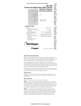
SPECIFICATIONS
Voltage............................120VAC, 60HZ
Load Requirements:
Single Pole Circuit..........25 to 500 Watt Incandescent, Fluorescent
Three-Way Circuit...........50 to 500 Watt Incandescent, Fluorescent
Horsepower Rating........1/6 horsepower
Time Adjustment..............Fixed 15 min, 10 min, 3 min, 15 sec
Light Level Adjustment.....Fixed 13 FC
Santa Clara, CA 95050 USA
1(800)879-8585 1(972)578-1699
US Patents:
4,787,722
4,874,962
5,124,566
5,640,113
Installation Instructions

UNIT DESCRIPTION AND OPERATION
The WR-100 is a motion sensing wall switch that controls residential
lighting based on occupancy. The sensor uses passive infrared tech-
nology to sense human motion in a space. Passive infrared technology
relies on line-of-sight to maintain coverage and therefore the sensor
must have a clear view of activity in the space. Obstructions, such as
furniture blocking the sensor’s lens, may prevent occupancy detection.
Note: Windows, glass shower doors, etc. will obstruct the
WR sensor’s view and prevent detection.
Through the WR-100’s featured mode selection, a user can specify
“On” functions, light level, and time delay.
ON-Mode Functions (Automatic-ON & Manual-ON):
Automatic-ON
In the Automatic-ON mode, the WR-100 automatically turns lights on
when a designated space becomes occupied.
Manual-ON
When the WR-100 is set to Manual-ON, users must turn the lights on
by pushing the Auto-ON/OFF button. The lights will not turn on auto-
matically with occupancy in the Manual-ON mode.
Note: In both Manual-ON and Automatic-ON, the Auto-
ON/OFF button can be pressed to turn the lights off. The
switch must be pressed again to turn the lights back on.
Light level function:
The light level feature holds lights off when there is sufficient daylight
present. To override this feature and turn the lights on, press the Auto-
ON/OFF button.
Time Delay function:
The WR-100 automatically turns lights off after a
space becomes vacant and a pre-set time inter-
val, or time delay, elapses.
Coverage Patterns
The WR-100 has a coverage range of 180
degrees and a maximal coverage area of 300
sq. ft. To maintain its coverage capacity and
optimally detect motion, the WR-100 must have
a clear and unobstructed view.
25'
10'
Call (800) 879-8585 For Technical Support

INSTALLATION & WIRING
WARNING
Disconnect power to wall box by removing fuse or turning
circuit breaker OFF before
: installing the WR-100, replacing
lamps, or doing any electrical work
Remove existing wall plate and mounting screws. Pull switch
from wall.
Identify type of circuit.
Single Pole Circuit (See Fig. 1.1)
Two single wires connect to two screws. A
ground wire may also be present and con-
nected to a ground terminal on the switch.
Follow the directions for wiring a single pole
circuit. (See Step 4 and Figs. 2.2 & 2.3)
Three- Way Circuit (See Fig. 1.2)
Three single wires connect to three screws.
One screw is a different color or labeled
“common." Tag the wire connected to this
screw for identification. Depending on the
switch’s location, this wire is either hot or
load. A ground wire may also be present
and connected to a ground terminal on the
switch. Follow the directions for wiring a
three-way circuit. (See Step 4 and Figs. 2.4
& 2.5.)
Ground
Fig 1.1
Ta g
Ground
Fig 1.2
Prepare Wires.
Strip the wires to the length (approximately 1/2 inch) indicated by the
“Strip Gage,” located on the back of the WR-100.
1
2
3
www.wattstopper.com

Wire the sensor.
Fig. 2.1
back-wire hole
Single Pole Circuit (See Fig 2.2 & 2.3)
• Connect the green or non-insulated (copper) ground wire to the
green terminal of the WR-100.
• Connect a wire to the COMMON (or odd colored) terminal.
• Connect the remaining wire to the L1 terminal.
Note: The L2 terminal is not used in a single pole application.
Ground
Fig 2.2
WR
Ground
Blk
Load
GR
L1COM
Hot
single pole circuit
Fig 2.3
Three-Way Circuit (See Fig 2.4 & 2.5 on the next page)
• Connect the green or non-insulated (copper) ground wire to
the green terminal of the WR-100.
4
• Connecting Wires (See Fig 2.1)
Use the following steps to connect wires.
• Loosen clamping screws. Insert stripped wire into back-wire hole.
Tighten clamping screw.
Call (800) 879-8585 For Technical Support

• Connect the tagged (common) wire to the COMMON (or odd col-
ored) terminal of the WR-100.
• Connect a single wire to L1 and L2 terminals respectively.
Notes about three way operation:
• If the switch backlight does not light after applying power, reverse
the placement of the L1 and L2 connected wires.
• Three way operation is only recommended for applications with
two WR-100s.
• When a WR-100 is used in a three-way application with another
WR-100, the duration of the time delay will be dependent upon the
last sensor triggered or the sensor with the longest time delay.
• If the WR-100 is used with a standard toggle switch, the toggle
switch must be turned on for the WR-100 to operate.
• If the WR-100 is not replacing another switch and is being newly
installed, the hot wire must be identified for connection to the com-
mon terminal.
Fig 2.4
Ta g
Ground
WR
Ground
GR L2
L1COM
WR
Ground
GR L2
L1COM
Load
Traveler
Traveler
Blk
Hot
Fig 2.5
Mounting and Alignment of WR-100
• Orient the WR-100 with its lens positioned above the Auto-ON/OFF
switch (lens up) and mount to wall box.
• Attach the wall plate.
Restore power.
6
5
www.wattstopper.com

Select the mode.
There are four selectable modes. Each mode determines the time
delay, On-mode, and light level settings. Chart 1 describes the
functionality of each mode.
To select a mode:
• Use the Auto ON/OFF button to first turn the lights on. Then press
and hold the Auto ON/OFF button until the lights turn off. If the
WR-100 is used in a three-way application, make certain the lights
are off by turning both WR-100s off and then select a mode for
each WR-100 indivdually.
• The red LED will blink to indicate the current operation mode. The
number of blinks corresponds to the mode number (i.e, three
blinks: mode three). Press the Auto-ON/OFF button to move
sequentially through the modes. The sequential series restarts at
mode one after advancing past mode four.
• Wait until the LED stops flashing (about 20 seconds). The lights will
turn on as an indication that the mode is set.
Note: Pressing the Auto-ON/OFF button before 20 seconds elapses
will change the mode.
CHART 1 Mode Selection
Time On Light
Mode Delay Mode Level
1
(factory pre-set) 15 min Auto-ON enabled
2 10 min Manual-ON disabled
3 3 min Auto-ON disabled
4 15 sec Auto-ON disabled
Recommended Uses:
Mode 1 laundry, bathroom, garage, general use
Mode 2 bedroom
Mode 3 pantry, closets
Mode 4 test mode
7
Call (800) 879-8585 For Technical Support

Note: When the WR-100 is in the Auto-ON mode, press the
Auto-ON/OFF button to turn on the lights initially. After the time
delay elapses, the unit will function automatically. Anytime
power is lost to the sensor, this initialization procedure with the
Auto ON/OFF button must be repeated in order to turn on the
lights.
If you experience any difficulties, refer to the troubleshooting sec-
tion.
TROUBLESHOOTING
To test the sensor:
Set the sensor to mode four. Move within the coverage zone of the
sensor to trigger detection.The red LED should flash. Then move
out of the coverage zone. The lights should turn off within 15 sec-
onds. Repeat as necessary to ensure that the desired coverage
areas are within detection range.
Lights will not turn on (green back-light is visible):
• Press Auto-ON/OFF button. Lights should turn on. If not, check
sensor wire connections.
• Make sure the mode is set to an Auto-ON mode (modes one,
three, or four).
• See Step 4 on three-way installation for additional notes.
Lights will not turn on (back-light is NOT visible):
• Check sensor wire connections
• Make certain that the circuit breaker is on and functioning
• Check the light bulb
• Call 1-800-879-8585 for technical support
www.wattstopper.com
The WR-100 is ready for operation. The lights will now turn on
and off according to the mode set.
8

Putting a Stop to Energy Waste®
Lights will not turn off:
• Make sure no motion is occurring in the coverage area until the
time delay expires.
• Check the mode setting to verify selection of desired time delay.
Also, when mode two (Manual-ON) is being used, there is a 30
second reset delay after the lights turn off. If motion is detected
during this time, the sensor will turn the lights back on without
having to push the Auto-ON/OFF button.
WARRANTY
The Watt Stopper, Inc. warrants its products to be free of defects in
materials and workmanship for a period of five years.
This product is designed for residential applications only. Use
of the WR-100 in a commercial application will void the warranty.
There are no obligations or liabilities on the part of The Watt
Stopper, Inc. for consequential damages arising out of or in con-
nection with the use or performance of this product or other indirect
damages with respect to loss of property, revenue, or profit, or cost
of removal, installation or reinstallation.
Santa Clara CA 95050 1(800)879-8585 1(972)578-1699
01425R3 6/01
Lens
Auto ON/OFF button; with
green back-light
Red LED indicates detection
/