
SR5 Technical Manual TSP010.doc Issue 3.0 - October 2001
This document is the private unpublished property of Money Controls Ltd and may not be reproduced in part or in
total by any means, electronic or otherwise, without the written permission of Money Controls Ltd. Money Controls
Ltd does not accept liability for any errors or omissions contained within this document. Money Controls Ltd shall
not incur any penalties arising out of the adherence to, interpretation of, or reliance on, this standard. Money
Controls Ltd. reserves the right to amend, improve or change the product referred to within this document or the
document itself at any time.

SR5 Technical Manual TSP010.doc Issue 3.0 - October 2001
CONFIDENTIAL
Not to be disclosed without prior written permission from Money Controls
Page 2 of 50
Contents
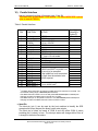
1) Diary of changes .............................................................................................................................. 4
2) Introduction....................................................................................................................................... 5
3) Operation.......................................................................................................................................... 6
4) UK AWP Industry Standard.............................................................................................................. 7
5) Electrical Connections...................................................................................................................... 8
6) Stud Positions .................................................................................................................................. 9
7) Electrical Interface Requirements .................................................................................................. 10
♦ Accept Common (COM A) .......................................................................................................... 10
♦ Standard Inputs .......................................................................................................................... 11
8) Alarms ............................................................................................................................................ 12
♦ Power-up Diagnostics................................................................................................................. 12
9) Dual Coin Rundown Interface (DCE) .............................................................................................13
10) Parallel Interface......................................................................................................................... 14
♦ Ident Pin...................................................................................................................................... 14
♦ Coin Accept Outputs................................................................................................................... 15
♦ Select Input ................................................................................................................................. 17
♦ Inhibit Lines................................................................................................................................. 18
♦ Bank Select Parallel Inputs (Modes 1, 4, 7 and 8) ..................................................................... 19
11) Sorting Coins .............................................................................................................................. 20
♦ 4-way Sorter ............................................................................................................................... 20
♦ 8-way Sorter (Active Manifold) ................................................................................................... 20
12) Sorter Overrides ......................................................................................................................... 21
♦ 4-Way Override........................................................................................................................... 21
♦ 8-Way Override........................................................................................................................... 22
13) Sorting Modes............................................................................................................................. 23
♦ Routing Plug (4 way sorting only)...............................................................................................23
♦ Using the routing plug................................................................................................................. 23
♦ EEPROM mode (4-way / 8-way sorting)..................................................................................... 23
14) Protocol....................................................................................................................................... 24
♦ Serial Interface............................................................................................................................ 24
15) Active Manifold Interface ............................................................................................................ 25
16) Diagnostics ................................................................................................................................. 26
♦ Inhibit/Accept line and Inductive Noise Test............................................................................... 26
♦ Solenoid and Inductive Sensor Flash Test................................................................................. 27
♦ Opto Test .................................................................................................................................... 28
♦ Exit Diagnostics .......................................................................................................................... 28
17) Bank Select Switches ................................................................................................................. 29
18) Rotary Switch Options. ............................................................................................................... 30
♦ Token Group Selection ............................................................................................................... 30
♦ Teach and Run Token “F”........................................................................................................ 31
♦ Alarm and Rundown settings “D”................................................................................................ 32
♦ Routing Plug / EEPROM mode “E”............................................................................................. 33
19) cctalk Serial Messages ............................................................................................................... 34
20) cctalk Interface Circuits............................................................................................................... 37
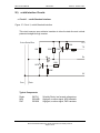
♦ Circuit 1 – cctalk Standard Interface...........................................................................................37
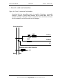
♦ Circuit 2 – cctalk Low Cost Interface .......................................................................................... 38
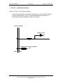
♦ Circuit 3 – cctalk Direct Interface................................................................................................ 39
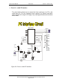
♦ Circuit 4 – cctalk PC Interface .................................................................................................... 40
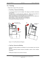
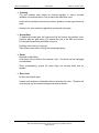
21) Servicing ..................................................................................................................................... 41
♦ Front Entry - Removal and Refitting ........................................................................................... 41
♦ Top Entry - Removal and Refitting ............................................................................................. 41
♦ Cleaning...................................................................................................................................... 42
♦ Accept Gate ................................................................................................................................ 42
♦ Sorter .......................................................................................................................................... 42
♦ Rear Cover ................................................................................................................................. 42
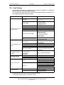
22) Fault Finding ............................................................................................................................... 43

SR5 Technical Manual TSP010.doc Issue 3.0 - October 2001
CONFIDENTIAL
Not to be disclosed without prior written permission from Money Controls
Page 3 of 50
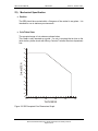
23) Mechanical Specification ............................................................................................................ 44
♦ Position ....................................................................................................................................... 44
♦ Coin/Token Sizes........................................................................................................................ 44
♦ Specified EMC Performance ...................................................................................................... 45
♦ Environmental specification ........................................................................................................ 45
♦ Material Flammability Rating ...................................................................................................... 45
♦ Top Entry dimensions ................................................................................................................. 46
♦ Front Entry Dimensions .............................................................................................................. 47
24) Label Details ............................................................................................................................... 48
Tables
Table 1: SR5 Rear Cover Details. ........................................................................................................... 8
Table 2: Power Supply .......................................................................................................................... 10
Table 3: Current Consumption .............................................................................................................. 10
Table 4: COM A DC Input Characteristics............................................................................................. 10
Table 5: Standard Input DC characteristics........................................................................................... 11
Table 6: Parallel Interface...................................................................................................................... 14
Table 7: Accept output DC characteristics ........................................................................................... 16
Table 8: 5 Coin Mode Accept Outputs (standard – Mode 1)................................................................ 17
Table 9: 16 Coin Mode Accept Outputs (standard – Mode 1)............................................................... 17
Table 10: cctalk Serial Commands........................................................................................................ 34
Table 11: Error Codes ........................................................................................................................... 36
Table 12: Fault Codes ........................................................................................................................... 36
Table 13: Status Codes ......................................................................................................................... 36
Table 14: Environmental Ranges .......................................................................................................... 45
Figures
Figure 1: Standard Top Entry configuration using bezel and rundown ................................................... 7
Figure 2: SR5 Connector Side................................................................................................................. 8
Figure 3: Input Hardware Configuration ................................................................................................ 11
Figure 4: DCE Connector Pin Outs ....................................................................................................... 13
Figure 5: Accept Outputs (1) ................................................................................................................. 15
Figure 6: Accept Outputs (2) ................................................................................................................. 16
Figure 7: 4-way sorter paths.................................................................................................................. 20
Figure 8: 8-way Active Manifold sorter paths ........................................................................................ 20
Figure 9: Sorter Overrides 4-way .......................................................................................................... 21
Figure 10: Sorter Overrides 8-way ........................................................................................................ 22
Figure 11: Routing Plug Connections.................................................................................................... 23
Figure 12: cctalk pin header .................................................................................................................. 24
Figure 13: Active manifold header........................................................................................................ 25
Figure 14: Active Manifold connector .................................................................................................... 25
Figure 15: Bank Select switches ........................................................................................................... 29
Figure 16: Rotary switch........................................................................................................................ 30
Figure 17: Circuit 1, cctalk Standard Interface ...................................................................................... 37
Figure 18: Circuit 2, cctalk Low Cost Interface...................................................................................... 38
Figure 19: Circuit 3, cctalk Direct Interface ........................................................................................... 39
Figure 20: Circuit 4, cctalk PC Interface................................................................................................ 40
Figure 21: Front Entry Removal Diagram.............................................................................................. 41
Figure 22: SR5 Accepted Coin Dimensions Graph ............................................................................... 44
Figure 23: SR5 Top Entry with Sorter Dimensions................................................................................ 46
Figure 24: SR5 Front Entry Dimensions................................................................................................ 47
Figure 25: SR5 Label Details................................................................................................................. 48
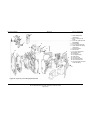
Figure 26: Top Entry / Front Entry Exploded View................................................................................49

SR5 Technical Manual TSP010.doc Issue 3.0 - October 2001
CONFIDENTIAL
Not to be disclosed without prior written permission from Money Controls
Page 4 of 50
1) Diary of changes
Issue 1.0………………………………………………………….……………………………January 2001
Issue 2.0…………………………………………………………….………………….………….April 2001
Amended Fig 1.
SR5 Label detail added.
Added a line to Teach and Run procedure.
Removed power-up diagnostics – Credit sensor blocked/faulty.
Exit diagnostics modified.
Added coin diameter/thickness graph.
Addition of new Modes.
Issue 3.0…………………………………………………………….………………….……October 2001
cctalk details added.
Last page disclaimer amended.
Fig 21 amended.
Accept flap removal updated.
Reference to C220B removed from Mode 3.
Mode 10 now C220B only.
Diagram of stud positions added.

SR5 Technical Manual TSP010.doc Issue 3.0 - October 2001
CONFIDENTIAL
Not to be disclosed without prior written permission from Money Controls
Page 5 of 50
2) Introduction
The SR5 series of coin acceptors has been designed to be compatible with the
standard 5” format currently used throughout the vending, amusement and
leisure industries.
Through the development of Series Resonance technology, the SR5
incorporates the highest levels of discrimination and functionality. Each
acceptor within the series will accept up to 16 different coins or 15 coins plus
one token.
Depending on your requirements, the SR5 series can be set-up to be backward
compatible with the C220B, C420, C435, C435 UK AWP and C450. This will be
determined by the Mode.
Mode 1 = C435
Mode 2 = C435 - BACTA Binary
Mode 3 = C420
Mode 4 = C435 - Customer Selectable Credit Codes
Mode 5 = C450/5 BDTA - 12 Coin
Mode 6 = Custom PCB
Mode 7 = C435 - Customer Selectable Credit Codes - C420 (Mode3) Inhibits
Mode 8 = C435 - Customer Selectable Credit Codes - BACTA (Mode2) Inhibits
Mode 9 = 16 coin BDTA - Custom Credit Codes - Custom Inhibits
Mode 10 = C220B
(See Manual TSP021 for further interface details).
As with all new Money Controls products other enhancements have been made
to the SR5 series as well as the new sensing technology.
These include:-
¾
cctalk serial communication.
(see appendix “SR5 cctalk”)
¾
Extended Teach and Run™ options.
(see appendix “SR5 MechTool”)
¾ Coinless programming.
¾ Adjustable coin security.
(see appendix “SR5 MechTool”)
¾ MechTool programmability.
(see appendix “SR5 MechTool”)
¾ Improved sorter coin detection.

SR5 Technical Manual TSP010.doc Issue 3.0 - October 2001
CONFIDENTIAL
Not to be disclosed without prior written permission from Money Controls
Page 6 of 50
3) Operation
Coin validation parameters are factory programmed for optimum acceptance of
up to 16 different coins or tokens and therefore no field adjustment is necessary
beyond token select / Teach and Run (see page 31).
However, the SR5 can now be programmed on site without the use of coins and
for total flexibility, if a new coin/token is required, the Teach and Run function
can be used to program all 16 coins and the token position 12.
Coins are inserted into a front or top entry acceptor and roll past a set of Series
Resonant sensors. If the characteristics measured from the inserted coin
match the stored window readings in all respects, then the coin is recognised as
being true. The accept gate will then open and the coin will pass through the
accept sensor. Once this happens the SR5 will send a predefined credit signal
to the host machine which will correspond to the coin accepted.
Depending on the SR5 model configuration the coin may then be diverted to
one of 4 different paths or 8 paths if using an active manifold.
If, on comparing the inserted coins characteristics, to all the pre-programmed
parameters, the coin readings do not match, this coin will be deemed invalid,
the accept gate will remain closed and the coin will travel through to the reject
via the reject path. The position of the reject path will be subject to whether a
direct reject or indirect reject option has been fitted.

SR5 Technical Manual TSP010.doc Issue 3.0 - October 2001
CONFIDENTIAL
Not to be disclosed without prior written permission from Money Controls
Page 7 of 50
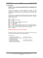
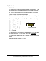
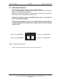
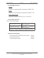
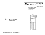
4) UK AWP Industry Standard
The UK AWP Standard SR5 is covered in detail in the appendix “SR5 UK
AWP”.
Basically, this would consist of a Top Entry SR5, Manifold 6, Universal
Rundown and Coin Entry Bezel.
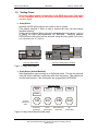
Figure 1: Standard Top Entry configuration using bezel and rundown
P
B
L
/
7
3
4
1
385
10
185
78.5

SR5 Technical Manual TSP010.doc Issue 3.0 - October 2001
CONFIDENTIAL
Not to be disclosed without prior written permission from Money Controls
Page 8 of 50
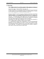
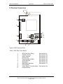
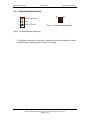
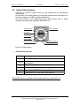
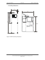
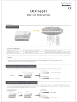
5) Electrical Connections
Figure 2: SR5 Connector Side
Table 1: SR5 Rear Cover Details.
1 DCE (Dual Coin Entry) See section 9).
2 Parallel Interface See section 10).
3 Sorter Override See section 12).
4 Routing Plug See section 13).
5 Serial interface (cctalk) See section 14).
6 Active Manifold See section 15).
7 Diagnostics See section 16).
8 Bank Select Switches See section 17).
9 LED Indicator
10 Token Select / Function Switch See section 18).
11 Program Button
1
2
3
4
56
8
9
10
11
7

SR5 Technical Manual TSP010.doc Issue 3.0 - October 2001
CONFIDENTIAL
Not to be disclosed without prior written permission from Money Controls
Page 9 of 50
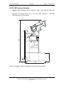
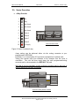
6) Stud Positions
The stud positions shown below are factory fitted at MCL.
“A” represents Money Controls backchannel compatible.
“B” represents Industry Standard backchannel compatible.
“C” is a customer specific option requested.

SR5 Technical Manual TSP010.doc Issue 3.0 - October 2001
CONFIDENTIAL
Not to be disclosed without prior written permission from Money Controls
Page 10 of 50
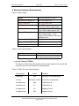
7) Electrical Interface Requirements
Table 2: Power Supply
Voltage: +12V to +24V DC +/- 10%
Absolute (NOT MODE 9): Min +10V Max +27V
MODE 9 Absolute: Min +12V Max +40V
Min / Max rise time: 5ms / 500ms
(From 0V to within supply range)
Min / Max fall time: 5ms / 500ms
(From within supply range to 0V)
Acceptor Power up time: 200 ms from the application of a
valid voltage supply. A valid
supply must be between the limits
specified above.
Ripple voltage [ < 120Hz ]: < 1 Volt
Ripple voltage [ > 120Hz ]: < 100mV
Ripple voltage [ > 1KHz ]: < 20mV
Table 3: Current Consumption
Typically: 70mA
Maximum: 2.0A with sorter.
3.0A with sorter and active manifold.
♦ Accept Common (COM A)
This input is used to select the polarity of the accept signal and to provide the
current for any user load, driven by an accept output.
Table 4: COM A DC Input Characteristics
Characteristic Value Condition
I leak max 1mA Off load, i.e. no accept active
I in max User load +20mA On load i.e. accept active
V positive max +24V Positive Com A
V positive min 5V Positive Com A
V negative min 0V Negative Com A
V negative max -24V Negative Com A

SR5 Technical Manual TSP010.doc Issue 3.0 - October 2001
CONFIDENTIAL
Not to be disclosed without prior written permission from Money Controls
Page 11 of 50
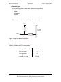
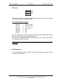
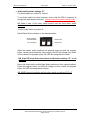
♦ Standard Inputs
All the following inputs have the same electronic configuration:
- Inhibits
- Bank Select
- Diagnostics
- Overrides
- Select
The hardware configuration for this input is shown below:
Figure 3: Input Hardware Configuration
Table 5: Standard Input DC characteristics
Characteristic Value
V in Low (max) 1V
V in High (min) 4V
I max @ V in Low 0.5mA
10K
47K
INPUT
+5V
SR5

SR5 Technical Manual TSP010.doc Issue 3.0 - October 2001
CONFIDENTIAL
Not to be disclosed without prior written permission from Money Controls
Page 12 of 50
8) Alarms
When enabled, an alarm condition will activate the accept lines with the binary
pattern 10111, (no Accept 4), for 80ms or for as long as the fault exists,
depending on the alarm condition.
Conditions that will indicate an alarm condition are:
1. A coin travelling backwards past the inductive sensors which indicates a
fraud is being attempted.
2. If the sorter optos are blocked for more than 1.5 seconds, the alarm signal
will remain active, for the duration of the blockage.
To turn the alarms ON or OFF see page 32 ‘Alarm and Rundown settings “D”’.
♦ Power-up Diagnostics
When the SR5 powers up, it performs an EEPROM self-check. If there is a
problem with the checksum, the LED will turn red and no coins will be accepted.
If diagnostic self check is enabled, the following are checked and if there is a
problem then the accept lines will show the alarm code, for as long as the fault
is present.
1. Blockage in the sensor area / faulty sensor.
2. EEPROM checksum
3. If a sorter is fitted the optics are checked for a blockage.
NB: If a sorter should be fitted but has been removed, then the SR5 will think
the sorter optics are blocked and therefore the alarm condition will be
permanent. This can only be rectified by re-fitting a sorter or re-programming
the SR5.
When the blockage / fault is rectified, the alarm code will automatically be
removed, except for a checksum error where the power has to be removed and
re-applied.

SR5 Technical Manual TSP010.doc Issue 3.0 - October 2001
CONFIDENTIAL
Not to be disclosed without prior written permission from Money Controls
Page 13 of 50
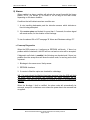
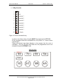
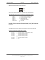
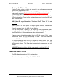
9) Dual Coin Rundown Interface (DCE)
Figure 4: DCE Connector Pin Outs
This interface is used with the dual coin rundown. It is used to provide
information to the SR5 indicating whether a coin or a token has been entered.
Normally, when there is no coin or token in the entry, both the opto detectors
are active as they are receiving infrared light from the corresponding emitter.
This is the quiescent state.
When a coin or token is entered then the light path between the corresponding
emitter and detector is broken and the detector becomes inactive.
Once the coin has passed the optics, the system returns to its quiescent state.
Opto Emitter Supply
Opto Detector A (token) Input
Opto Detector B (coin) Input
Not Used
Key
Ground
1
2
3
4
5
6

SR5 Technical Manual TSP010.doc Issue 3.0 - October 2001
CONFIDENTIAL
Not to be disclosed without prior written permission from Money Controls
Page 14 of 50
10) Parallel Interface
Industry standard interface. Connector type: 21 pin SIL
This table only shows MODE 1 SR5 details. For other MODE SR5’s please
refer to manual TSP021.
Table 6: Parallel Interface
PIN FUNCTION ACTIVE
Input (I) /
Output(O) /
Power(P)
1 Ident COM A I/O
2 Accept 5 COM A O
3 Accept COM
(COM A)
+5V to +24V DC
0V to -24V DC
I and P
4 Accept 1 COM A O
5Key
6 Accept 2 COM A O
7 Accept 3 COM A O
8 Select NC / 5V = 5 coin mode.
Low = 16 coin mode.
I
9 Accept 4 COM A. O
10 Inhibit 4 See below. I
11 +V 12 – 24V DC. P
12 0V P
13 Inhibit 3 I
14 Inhibit 2 I
15 Inhibit 1 I
16 Inhibit 5 I
17 Inhibit 6 I
18 Inhibit 7 I
19 Inhibit 8
Inhibit lines MUST be pulled Low,
for a coin to be accepted.
If the inhibit line is not connected
or High, then the selected coin
will be rejected.
I
20 Bank Select 1 I
21 Bank Select 2
Low to Inhibit bank
1
.
I
1
The Bank Select inputs are connected in parallel with the DIL switches on the PCB. The
normal state, floating /High, is Selected (Bank Enabled).
If the Bank Select DIL switch is set to the ON position De-selected (Bank Inhibited) then
changing the state of the Bank Select input will have no effect.
If the Bank Select pin on the parallel connector is Low, De-selected (Bank Inhibited) then
changing the state of the Bank Select DIL switch will have no effect.
♦ Ident Pin
The ident pin (pin 1) can be used by the host machine to identify the SR5
acceptor and hence interpret the binary credit code outputs.
The ident pin is linked on board to COM A and will reflect COM A status
providing pin 8, (select), is Low. The ident pin status will change within 10ms of
a change in the select line status.

SR5 Technical Manual TSP010.doc Issue 3.0 - October 2001
CONFIDENTIAL
Not to be disclosed without prior written permission from Money Controls
Page 15 of 50
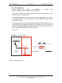
♦ Coin Accept Outputs
These outputs are capable of functioning as current sink,
(negative COM A) or current source (positive COM A).
If the value of COM A is outside the specification, then the performance of the
Accept outputs is not guaranteed.
On acceptance of a true coin, the transistors (COM A dependant) are turned on
for a period of 80ms
(2)
(+/- 5%) to within 1 volt of COM A at a Max. current
source/sink of 50mA.
The host machine must look for valid credit pulses NOT LESS THAN 50ms. It is
not sufficient to merely detect the edges of credit pulses. This ‘de-bounce’ will
prevent credits being registered by the host machine as a result of any noise or
false credit pulses being induced on the output lines.
(2)
Default time.
Figure 5: Accept Outputs (1)
ComA = +5V to +24V
0V
50mA MAX
O/P
Coin Accept
O/P
80ms
MAX 24V
0V
+5V to +24V
SR5
Host machine
COMA = +5V to +24V

SR5 Technical Manual TSP010.doc Issue 3.0 - October 2001
CONFIDENTIAL
Not to be disclosed without prior written permission from Money Controls
Page 16 of 50
Table 7: Accept output DC characteristics
Characteristic Value Conditions
V out active min. Com A minus 1V Positive Com A
V out active max. Com A plus 1V Negative Com A
I max (sink or source) 50mA Positive or Negative Com A
I Leakage
10µA
Off
Figure 6: Accept Outputs (2)
80ms
ComA = 0V
+5V to +24V
50mA MAX
O/P
Coin Accept
O/P
MAX 24V
0V
+5V to +24V
SR5
Host machine
COMA = 0V
80ms
ComA = -5V to -24V
0V
50mA MAX
O/P
Coin Accept
O/P
MAX 24V
-5V to -24V
0V
SR5
Host machine
COMA = -5V to -24V

SR5 Technical Manual TSP010.doc Issue 3.0 - October 2001
CONFIDENTIAL
Not to be disclosed without prior written permission from Money Controls
Page 17 of 50
♦ Select Input
This input determines whether the SR5 is in 5 coin mode or 16 coin mode. 5
coin mode uses a single output per coin and is therefore limited to 5 different
credit codes.
A High will select 5 coin mode whilst a Low will select 16 coin mode.
The default condition is High and therefore 5 coin mode.
Table 8: 5 Coin Mode Accept Outputs (standard – Mode 1)
Credit Code Accept 1 Accept 2 Accept 3 Accept 4 Accept 5
1 10000
2 01000
3 00100
4 00010
5 00001
5 coin mode credit patterns (1 = Active, 0 = Inactive)
In 16 coin mode a binary pattern is output on the Accept lines using A1, A2, A3
and A5. A4 is used as a strobe to indicate a valid credit pattern.
Table 9: 16 Coin Mode Accept Outputs (standard – Mode 1)
Credit Code Accept 5
Accept 4
(Strobe)
Accept 3 Accept 2 Accept 1
1 01000
2 01001
3 01010
4 01011
5 01100
6 01101
7 01110
8 01111
9 11000
10 11001
11 11010
12 11011
13 11100
14 11101
15 11110
16 11111
16 coin mode credit patterns
(only valid when Accept 4 is Active. 1 = Active, 0 = Inactive)
** For other SR5 variants, (page 5), please refer to TSP021: **

SR5 Technical Manual TSP010.doc Issue 3.0 - October 2001
CONFIDENTIAL
Not to be disclosed without prior written permission from Money Controls
Page 18 of 50
♦ Inhibit Lines
The Inhibit inputs define whether a programmed coin will be accepted or not.
Which coins are affected by the inhibit inputs is decided in conjunction with the
Bank Select inputs. (See next section).
If the Inhibit pin is not connected OR High then the corresponding coin will be
inhibited i.e. Rejected.
If the Inhibit pin is Low then the corresponding coin will be accepted if deemed
to be true.
NB: The default setting is for ALL inhibit inputs to be High and therefore coins
are inhibited.

SR5 Technical Manual TSP010.doc Issue 3.0 - October 2001
CONFIDENTIAL
Not to be disclosed without prior written permission from Money Controls
Page 19 of 50
♦ Bank Select Parallel Inputs (Modes 1, 4, 7 and 8)
The SR5 is capable of accepting up to 16 different coin types.
Whilst it is possible for the coins to operate entirely independently, for the
purposes of inhibiting coins they are arranged in 2 banks of 8.
It is therefore only necessary to have 8 inhibit inputs (1 per coin in each bank).
Each of the Bank Select inputs controls its relevant bank (1 or 2).
Bank 1 contains coins 1 to 8.
Bank 2 contains coins 9 to 16.
When a Bank Select input is Low
3
, then the corresponding bank of coins are
de-selected (i.e. inhibited).
When a Bank Select input is High
4
, then the corresponding bank of coins are
selected (i.e. enabled).
The 8 inhibit inputs only act on the coins in the bank/s that are selected.
Examples.
When both Bank Select inputs are High then both banks of coins are selected.
In this state the 8 inhibit lines act on all 16 coins, i.e.
Inhibit 1 controls coin 1 and coin 9.
Inhibit 2 controls coin 2 and coin 10.
Inhibit 3 controls coin 3 and coin 11 and so on up to
Inhibit 8 controls coin 8 and coin 16
When Bank Select 1 input is High and Bank Select 2 input is Low then coin
bank 1 is selected and coin bank 2 is de-selected, i.e.
Inhibit 1 controls coin 1.
Inhibit 2 controls coin 2.
Inhibit 3 controls coin 3 and so on up to
Inhibit 8 controls coin 8.
When Bank Select 1 input is Low and Bank Select 2 input is High then coin
bank 1 is de-selected and coin bank 2 is selected, i.e.
Inhibit 1 controls coin 9.
Inhibit 2 controls coin 10.
Inhibit 3 controls coin 11 and so on up to
Inhibit 8 controls coin 16.
Notes:
3
Pulling Bank select Low is the same as setting the DIL switch UP (the ON position).
4
Pulling Bank select High is the same as setting the DIL switch DOWN (the OFF position).

SR5 Technical Manual TSP010.doc Issue 3.0 - October 2001
CONFIDENTIAL
Not to be disclosed without prior written permission from Money Controls
Page 20 of 50
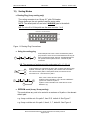
11) Sorting Coins
Due to the improvements incorporated in the SR5 4-way sorter, this sorter
is not compatible with any of the sorters previously manufactured by MCL
and vice versa.
♦ 4-way Sorter
Normally the SR5 will be used to sort coins to one of 4 paths.
(The passive manifold, if fitted, is used to channel the coins into the industry
standard footprint).
Sorting can be achieved either using the routing plug
(see Sorting Modes – page 23)
or having the paths pre-programmed into EEPROM. Switching between
EEPROM and routing plug can be achieved using the rotary switch
(see Routing
Plug / EEPROM mode “E”– page 33)
Figure 7: 4-way sorter paths
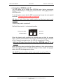
♦ 8-way Sorter (Active Manifold)
Other applications require sorting up to 8 different paths. This can be achieved
using the active manifold in conjunction with the 4-way sorter. This method can
only be used however, if the sorter paths are programmed in EEPROM.
Figure 8: 8-way Active Manifold sorter paths
View from below passive manifold.View from below sorter.
View from above.
+
REJECT
PATH D
PATH B
PATH A
PATH C
Path A
Path B
Path C
Path D
1/D
7/c
8/d 6/b
5/a
4/A3/B2/C
Reject
DEFAULT
SIDE
ACTIVE
MANIFOLD
TOP 4-way
BOTH
BOTTOM 4-way
NO
DIVERTER
DIVERTER
DIVERTERS
DIVERTERS
Page is loading ...
Page is loading ...
Page is loading ...
Page is loading ...
Page is loading ...
Page is loading ...
Page is loading ...
Page is loading ...
Page is loading ...
Page is loading ...
Page is loading ...
Page is loading ...
Page is loading ...
Page is loading ...
Page is loading ...
Page is loading ...
Page is loading ...
Page is loading ...
Page is loading ...
Page is loading ...
Page is loading ...
Page is loading ...
Page is loading ...
Page is loading ...
Page is loading ...
Page is loading ...
Page is loading ...
Page is loading ...
Page is loading ...
Page is loading ...
-
 1
1
-
 2
2
-
 3
3
-
 4
4
-
 5
5
-
 6
6
-
 7
7
-
 8
8
-
 9
9
-
 10
10
-
 11
11
-
 12
12
-
 13
13
-
 14
14
-
 15
15
-
 16
16
-
 17
17
-
 18
18
-
 19
19
-
 20
20
-
 21
21
-
 22
22
-
 23
23
-
 24
24
-
 25
25
-
 26
26
-
 27
27
-
 28
28
-
 29
29
-
 30
30
-
 31
31
-
 32
32
-
 33
33
-
 34
34
-
 35
35
-
 36
36
-
 37
37
-
 38
38
-
 39
39
-
 40
40
-
 41
41
-
 42
42
-
 43
43
-
 44
44
-
 45
45
-
 46
46
-
 47
47
-
 48
48
-
 49
49
-
 50
50


Ask a question and I''ll find the answer in the document
Finding information in a document is now easier with AI
Related papers


Other documents
-
Franke 0390572 Datasheet
-
-
OEHLBACH 6016 Datasheet
-
 Coinco 9302-CGX Installation guide
-
 Alberici ORYONE Quick Manual
-
 PIXIE DD1149H No Bull Blinds Wireless Emitter Operating instructions
-
 Mag-Nif Digital Coin Sorter 4860 Operating instructions
-
Diebold Nixdorf iCash 15E Operating instructions
-
Alloy AWPS-24T4SFP Quick Install Manual
-
BRAVILOR BONAMAT Bolero XL 433 S Owner's manual


