Page is loading ...

15”, 12.1”, & 10.4”
OPtima Touch PC
Appendixes
Appendix A. Phoenix Award BIOS ................................................................................................................... 15
Appendix B. Jumper Locations ........................................................................................................................ 57
HA136736_07 Page 1
Contents
1. Introduction .................................................................................................................................................. 3
2. Installation ..................................................................................................................................................... 3
2.1 CE EMC Compliance ...................................................................................................................... 3
2.2 Mounting .......................................................................................................................................... 3
2.3 Wiring ............................................................................................................................................... 3
2.4 Adding Hardware ............................................................................................................................ 3
2.4.1 Adding Boards .............................................................................................................................. 3
2.4.2 Changing Memory ........................................................................................................................ 6
3. Peripheral Devices ........................................................................................................................................ 7
4. The Operating System .................................................................................................................................. 7
4.1 BIOS Password Settings ................................................................................................................. 7
5. Setup .................................................................................................................................................... 8
5.1 Windows Setup................................................................................................................................ 8
5.1.1 Window Settings ........................................................................................................................... 8
5.1.2 Regional Settings for Date ........................................................................................................... 8
5.1.3 Date/Time Zone ............................................................................................................................ 8
5.1.4 Fonts .............................................................................................................................................. 8
5.2 Power Shutdown/Battery Backed Power Supply ......................................................................... 8
5.3 Backups............................................................................................................................................. 8
6. The Display .................................................................................................................................................... 9
6.1 The Touchscreen ............................................................................................................................. 9
7. Automatic Logon to Windows ..................................................................................................................... 9
7.1 Disabling AutoLogon ..................................................................................................................... 9
8. Troubleshooting/Application Tips ............................................................................................................. 9
9. Specifications .............................................................................................................................................. 10
10. End User License Agreement .................................................................................................................... 12
Figures
Figure 1. 15” Mounting Dimensions ................................................................................................................. 4
Figure 2. 10.4” Mounting Dimensions .............................................................................................................. 4
Figure 3. Port Locations on 10.4” and 15” ........................................................................................................ 4
Figure 4. 12.1” Mounting Dimensions .............................................................................................................. 5
Figure 5. Port Locations on 12.1” ....................................................................................................................... 5
Figure 6. OPtima Touch PC Board ....................................................................................................................

HA136736_07Page 2
Important Information
Regarding the OPtima Touch PC
1. Due to compatibility issues between Internet Explorer 7.0 (released fall 2006)
and Wonderware, do NOT install IE 7.0 at this time.
2. READ the Readme.txt file that appears in the C: directory or on the desktop
following powerup!
3. If a password is required, the factory default has been set to: password.
(It can be changed from within the operating system.)
4. To calibrate the touchscreen, select the touch utility menu under
START\PROGRAMS.
5. Set the clock to the time zone relevant to your area.
6. For units that require WindowsXP initialization, a CUSTOMER account (no
password required) will appear following this setup, along with any user
defined profiles made during the initialization process. The customer account
has been set to a more “classic” look (Windows 98/NT 4.0 style), giving an
example for users that may be more familiar with that style.
The customer account can be renamed or deleted (from System\Control\
User Accounts) if so desired.
For Windows 2000 units, an Administrator profile has been created. Profiles
can be modified from Control Panel/Users and Passwords.
7. Microsoft has discontinued OEM CD support for Windows 2000, which
prevents us from shipping a Windows 2000 CD with those units (although
Windows 2000 IS installed). However, the WindowsXP license allows OEMʼs
to ship legacy versions (like Windows 2000) by putting the WindowsXP
license on the unit. Although no Windows 2000 CDʼs can be shipped, a
Windows 2000 recovery image (back to an initialization state) is included on
the hard drive. In addition, a WindowsXP CD is shipped with the unit.
www.eurotherm.com

HA136736_07 Page 3
1. Introduction
The OPtima Touch Panel is a rugged, compact industrial computer combined
with either a 10.4”, 12.1” or 15” TFT touch screen monitor in one housing. It is
designed to serve as a general purpose human machine interface (HMI) and can
be ordered pre-configured with several HMI software packages.
2. Installation
Installation must be performed by a qualified technician.
This is an Installation Category 3 and Pollution Degree 2 device. The wiring
guidelines outlined in this manual are to be used in addition to all applicable
electrical and safety codes. Be sure to follow all requirements of such codes as
well as other recognized safety practices.
2.1 CE EMC Compliance
The OPtima Touch PC meets CE EMC requirements. For additional wiring
information, refer to the following publications:
Recommended Guideline for Wiring & Grounding Machine Controls
Society of the Plastics Industry, Inc.
1275 K Street, N.W.– Suite 400
Washington, D.C. 20005
(202) 371-5200
IEEE Guide for the Installation of Electrical Equipment to Minimize Electrical Noise
Inputs to Controllers from External Sources
(IEEE Std 518-1982)
2.2 Mounting
Do not enclose the operator station in a small or tightly sealed cabinet or panel
which would cause the surrounding temperature to exceed the rated tempera-
ture. Do not expose to direct sunlight or corrosive gas. Consideration must also
be given to protecting the display surface. Do not mount the operator station so
that the display is subject to mechanical damage or dust and dirt particles.
Periodic cleaning using a soft, water-dampened cloth is recommended. Do NOT
spray liquid cleaning agents directly onto the operator station. Allow adequate
room for vibration, air circulation and easy access. Pay particular attention to the
accessibility of cable connectors.
2.3 Wiring
All three sizes are equipped with a 115-230 Vac autosensing, 200W power
supply. Note that inadvertent power loss (or shutdown) may cause application
problems. A battery-backed power supply (or UPS) is recommended in order to
keep the OPtima running during times of power loss.
2.4 Adding Hardware
Observe proper ESD precautions (use an appropriately grounded wrist strap or
similar device) when installing any device.
2.4.1 Adding Boards
The OPtima Touch PC has 1 PCI expansion slot. PCI cards must be the
standard 4-3/4” (120mm) length – longer cards will not fit.
Card options that should function in the OPtima PC include network (ethernet,
etc.), modem, and serial cards. PCI serial cards that autodetect addressing may
work best.
Invensys Systems, Inc. 44621 Guilford Drive Suite 100, Ashburn, VA, 20147, USA
(+1 703) 724 7300

HA136736_07Page 4
Figure 2. 10.4” Mounting Dimensions
15 inch OPtima Touch PC
for Horizontal or Vertical Mounting
10.4 inch OPtima Touch PC
for Horizontal Mounting Only
this end up
for vertical mounting
Figure 3. Port Locations on 10.4” and 15”
Note that Com4 is shipped with jumpers set to RS-485 operation.
Figure 1. 15” Mounting Dimensions
Include a switch or circuit breaker in the installation. It must be placed in close proximity to the equipment,
within easy reach of the operator and must be marked as the disconnecting device for the equipment.
www.eurotherm.com

HA136736_07 Page 5
Include a switch or circuit breaker in the installation. It must be placed in close proximity to the equipment,
within easy reach of the operator and must be marked as the disconnecting device for the equipment.
Figure 4. 12.1” Mounting Dimensions
9.438 in
240 mm
11.625 in
295 mm
10.325 in
262 mm
12.380 in
314 mm
8.000 in
203 mm
9.342 in
237 mm
11.464 in
291 mm
10.250 in
260 mm
0.500 in
12.7 mm
5.625 in
143 mm
1.531 in
39 mm
USB2
Figure 5. Port Locations on 12.1”
12.1 inch OPtima Touch PC
for Horizontal Mounting Only
Invensys Systems, Inc. 44621 Guilford Drive Suite 100, Ashburn, VA, 20147, USA
(+1 703) 724 7300

HA136736_07Page 6
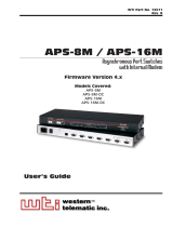
Figure 6. OPtima Touch PC Board
2.4.2 Changing Memory
A single 72 pin SIMM (Single In-line Memory Module) socket is available for
onboard system DRAM. The socket will contain a 512M memory module.
To remove the SIMM, support it with a finger and use a pen or similar shaped
object to press one retaining clip down. Repeat for the other side. When
released, the clips will push the SIMM up and out of its upright position. Remove
the SIMM from the socket.
To insert a SIMM, place it in at a moderate angle. Note that it fits in the socket in
only one direction. Push it in from an angle to an upright position. The retaining
clips will grab and click into place. When positioned properly, the pins on the top
of the vertical pins should rest in the holes of the SIMM modules.
90° Header
for PCI Card
Memory Module
Lithium Battery
P12
JP2 JP3
(COM4 Mode Select) (COM4 Signal Select)
JP4
(LCD Voltage Select)
(Jumpers as shipped for RS-485)
VORSICHT
Gefahr der Explosion, wenn Batterie nach einer falschen Art ersetzt wird.
Entledigen Sie sich benutzte Batterien entsprechend den Anweisungen.
ATTENTION
Il y a danger d’explosion s’il ya remplacement incorrect de la batterie.
Remplacer uniquement avec une batterie du meme type ou d’un equivalent
recommande par le constructeur. Mettre au rebut les batteries usagees
conformement aux instructions du fabricant.
ˆ ´
´´
´
CAUTION!
RISK OF EXPLOSION IF BATTERY IS REPLACED BY AN INCORRECT TYPE.
DISPOSE OF USED BATTERIES ACCORDING TO THE INSTRUCTIONS.
If necessary, replace battery with
BR2032 or equivalent.
www.eurotherm.com

HA136736_07 Page 7
3. Peripheral Devices
The OPtima Touch PC has an on-board flat panel/CRT controller. An internal
cable is used to connect the computer card to the flat panel screen. If desired, an
external CRT can be connected to the CRT connector on the side of the unit. An
external keyboard and mouse can also be plugged into the mini-DIN connectors
on the side of the unit.
A high speed, local bus IDE controller as well as a floppy controller are also
included. The IDE controller supports the internal hard drive. Depending on the
size of the hard drive, it will be partitioned into several drives, with sequential
letters assigned for each partition. To check partitions, go to Windows/My
Computer and select a drive. The size of the drive partition and how much of it is
used will be displayed in the lower part of the My Computer window. Be sure to
verify how much hard drive space remains before installing software. Filling a
hard drive partition to capacity can cause application anomalies. As a minimum,
50MB should be left as scratch pad space for an application’s temporary files. If
more room for an application is required, switch to a different drive partition.
The touchscreen is connected to COM3 by an external cable. Three additional
serial ports (COM1, COM2 and COM4), a parallel port, an Ethernet interface and
2 USB ports are also available. Note that COM$ is jumpered internally for RS-
485 operation.
4. The Operating System
The operating system for the OPtima Touch PC is Windows XP Professional or
Windows 2000. The BIOS is Award FLASH BIOS.
4.1 BIOS Password Settings
It is not recommended that users change the factory defaulted BIOS settings.
The computerʼs CMOS memory has an integral lithium battery that should last for
ten years in normal service. However, one area that may be of importance is the
password settings to allow changes in the BIOS. There are no default BIOS
Supervisor/User password settings as shipped from the factory. The difference
in supervisor and user passwords is that the supervisor can enter and change
the options of the setup menus, while the user can only see the main BIOS screen
and its options, but cannot select any of those options.
To set supervisor/user BIOS passwords, first connect an external keyboard (for
the Page Up/Page Down function). Press Del on power up. This takes the
computer into the AWARD BIOS setup. When the setup screen comes on, select
the supervisor password. A small screen appears for password definition (up to
eight characters), followed by a second screen to verify the entry. The method is
the same for the user password. Once passwords are defined, password entry
will be required before any BIOS settings can be changed.
IMPORTANT: There is no hidden entry into the BIOS settings! If the supervisor
password is forgotten, no modifications will be allowed. If you chose to use
passwords, make certain to record them.
To disable the password function, just press Enter when the Supervisor password
option appears. Once the password is disabled, setup access is freely available.
Consult the factory before making any significant BIOS settings. Making inappro-
priate modifications may disable the OPtima PC to the point of inoperation.
Invensys Systems, Inc. 44621 Guilford Drive Suite 100, Ashburn, VA, 20147, USA
(+1 703) 724 7300

HA136736_07Page 8
5. Setup
5.1 Windows Setup
5.1.1 Window Settings
The OPtima Touch PC will be delivered with almost all settings in their “default ”
mode. If you care to change any of these, or are unfamiliar with the appearance
and operation of Windows XP, Microsoft includes a “tour” of the system that is
both informative and helpful.
5.1.2 Regional Settings for Date
Windows is setup to use a four digit year for y2k compliance. The setting is found
underRegional Settings (in Control Panel ). Do not change this setting.
5.1.3 Date/Time Zone
The time zone is set for Greenwich Mean Time, with the option to adjust for
daylight savings time disabled. In cases where SPC data is being gathered, an
automatic adjust for the time can disrupt data being collected. This option can be
changed by selecting Date/Time (in Control Panel ) and changing the date/time
to the preferred option.
5.1.4 Fonts
When creating screen sets for use with the InTouch development system, the
user MUST use fonts that are also installed in the OPtima PC. It is recommended
to download sample screens before developing an entire screen set, in order to
make certain that fonts (and other items) appear as desired.
Installed Fonts include: Arial, Courier New, Lucida Console, Lucida Sans Unicoda,
Marlett, Times New Roman.
Versions of the above include Baltic, Central European, Cyrillic, Greek, Turkish,
and Western. If new fonts need to be installed, select Fonts (in Control Panel)
and from the File menu, select Install New Font. Point the computer to the
directory from which you are installing (i.e. A:\ ) and click OK.
5.2 Power Shutdown/Battery Backed Power Supply
Due to the way Windows operates, it is recommended that the OPtima Touch PC
be powered down through the Start menu Shut Down sequence. Inadvertent
power loss or shut down may cause application anomalies. A back up power source
is recommended in order to keep the OPtima running in case of a power loss.
5.3 Backups
As with all computer files, we suggest you make backups of all applications and
data. This can be accomplished by connecting to a computer network, or by
connecting an external drive through one of the USB ports. It is best to have a
mandatory backup plan in case of hard drive failure. Hard drives cannot be
reconstructed without backup files. Scheduling software can be purchased to
perform scheduled backups of critical files.
www.eurotherm.com

HA136736_07 Page 9
6. The Display
The 10.4” display is a standard flat panel screen with a resolution of 800
(horizontal) x 600 (vertical) pixels (SVGA). The12.1” and 15” displays have a
resolution of 1024 (horizontal) x 768 (vertical) pixels (XVGA). All are shipped
from the factory set for 65,535 colors.
6.1 The Touchscreen
The touchscreen uses an analog resistive technology. Care should be taken to
not puncture or scratch the surface with rough objects. Cursor movement can be
recalibrated at any time. To perform the calibration, go to Start , then Programs,
and select the appropriate Touch Utility. A calibration window will eventually
appear, asking you to touch a few areas on the screen. You will be prompted to
respond if the cursor moves. If cursor movement is not satisfactory, perform the
calibration sequence again.
7. Automatic Logon to Windows
Since the OPtima PC has no built-in keyboard functions, it is shipped from the
factory with the Windows AutoLogon feature enabled. This has been accomplished
by setting a username and password (under Start/Programs/Administrative
Tools/User Manager) and matching that password with the DefaultPassword
in the system registry (see below). For shipment the powerup user is “Administrator”
and the Default Password is “password.”
7.1 Disabling AutoLogon
Note that if autologon is to be disabled a keyboard will be required (for the CTL-
ALT-DEL poweron sequence and to enter a user name and password). To disable
the autologon function, enter a “0” (zero) for AutoAdminLogon (using the registry
editor as described below).
8. Troubleshooting/Application Tips
Note: In ANY situation that requires the unit to be open, proper shutdown
and ESD precautions MUST be followed.
Touchscreen stops working:
Plug in an external keyboard (a Windows 95 keyboard will give you the Start
key.) Using the Start , Tab and Arrow keys , go to Start/Programs/ Touch Utility
Menu. Look to see that the COM Port is set to single touchscreen/Com 3. If it
is not, set it to single touchscreen/Com3.
If the touchscreen still will not function, plug in a Windows 95 compatible
keyboard. This will allow a user to move around the screen using keyboard
functions.Start/Tab/Alt + alpha character and arrow keys should allow access
to most functions. When the system can be shut off, open the unit and look
for misconnection of power and cables.
When the System starts up, it performs a diskcheck:
This operation is generally performed if there was an improper shut down of the
unit. This does not cause any application anomalies, just a longer power up
while the disk is checked.
BIOS
Power Management must be set to ENABLED (if disabled, the might reset when
attempting to load Windows).
Invensys Systems, Inc. 44621 Guilford Drive Suite 100, Ashburn, VA, 20147, USA
(+1 703) 724 7300

HA136736_07Page 10
9. Specifications
Construction:
Heavy-duty steel chassis & plastic front panel with NEMA 12/IP54
LCD:
15” TFT 1024 x 768 (Horizontal or Vertical Mounting)
12.1” TFT 1024 x 768 (Horizontal Mounting Only)
10.4” TFT 800 x 600 (Horizontal Mounting Only)
Touch Screen:
Analog Resistive Continuous Resolution
Processor Speed:
1.36 GHz (minimum) Celeron, FSB 133MHz
DRAM:
512MB DIMM
BIOS:
Phoenix-Award
VGA Controller:
S3 ProSavage4 4xAGP 3D/2D SVGA up to 1600x1200 32 bit
VGA Memory:
32MB (shared)
VGA Port:
Supports simultaneous display with additional monitor
Ethernet:
(1) 10/100 Base-T Realtek RTL8139C RJ-45 connector
Serial Ports:
(3) RS-232 (COM1, COM2, COM3); (1) RS-232/422/485 (COM4)
Parallel Port:
(1) Parallel
USB Ports:
(2) USB
Storage:
40GB (standard)
512MB Flash Drive (optional)
Keyboard Port:
PS/2
Mouse Port:
PS/2
Expansion Slot:
(1) 32-bit PCI (half length)
www.eurotherm.com

HA136736_07 Page 11
Operating Systems:
Windows™ XP Professional (standard)
Windows™ XP Embedded (optional, required for flash drive)
Windows™ 2000 (standard)
Power Supply:
115 - 230 Vac, autosensing, 200 Watts
Temperature:
10.4”:
Ambient: 0 to +40°C (32 to 104°F)
Storage: –20 to +60°C (-4 to 140°F)
12.1” and 15”:
Ambient: 0 to +50°C (32 to 122°F)
Storage: –20 to +60°C (-4 to 140°F)
Operating Humidity:
10.4”:
5-95% @ 40°C (104°F), non-condensing
12.1” and 15”:
5-95% @ 50°C (122°F), non-condensing
Operating Shock:
5G, 11ms duration, half-sinewave
Operating Vibration:
10-58 Hz, 0.0375 mm 58-500 Hz; 0.5G
Protection Class (10.4” and 15”):
NEMA 12/IP54 (Front Side)
(IP65 attainable with additional mounting hardware - consult factory)
Battery:
Lithium battery for CMOS data retention
PC99 ACPI compliant (replace with BR2032 or equivalent - see Figure 6)
Invensys Systems, Inc. 44621 Guilford Drive Suite 100, Ashburn, VA, 20147, USA
(+1 703) 724 7300

HA136736_07Page 12
10. End User License Agreement
END USER LICENSE AGREEMENT FOR MICROSOFT SOFTWARE
IMPORTANT– READ CAREFULLY: This End-User License Agreement (“EULA”)
is a legal agreement between you (either an individual or a single entity) and the
manufacturer (“Manufacturer”) of the special purpose computing device
(”SYSTEM”) you acquired which includes Microsoft software product(s) installed
on the SYSTEM (“SOFTWARE PRODUCT” or “SOFTWARE”). The SOFTWARE
includes computer software, the associated media, any printed materials, and any
“online” or electronic documentation. By installing, copying or otherwise using
the SOFTWARE, you agree to be bound by the terms of this EULA. If you do not
agree to the terms of this EULA, Manufacturer, Microsoft Corporation (“Microsoft”)
and Microsoft Licensing, Inc. (MSLI) are unwilling to license the SOFTWARE to
you. In such event, you may not use or copy the SOFTWARE, and you should
promptly contact Manufacturer for instructions on return of the unused product(s)
for a refund.
SOFTWARE LICENSE
The SOFTWARE is protected by copyright laws and international copyright
treaties, as well as other intellectual property laws and treaties. The SOFTWARE
is licensed, not sold.
1. GRANT OF LICENSE. This EULA grants you the following rights:
• Software. You may use the SOFTWARE as installed on the SYSTEM.
• Application Sharing. The SOFTWARE may contain technology that enables
applications to be shared between two or more SYSTEMS, even if an
application is installed on only one of the SYSTEMS. You should consult
your application license agreement to determine whether sharing the
application is permitted by the licensor.
• Storage/Network Use. If the SOFTWARE PRODUCT is installed on the
SYSTEM over an internal network from a server, you must acquire and
dedicate a license for the SOFTWARE PRODUCT for each SYSTEM on
which the SOFTWARE PRODUCT is used or to which it is distributed. A
license for the SOFTWARE PRODUCT may not be shared or used concurrently
on different SYSTEMS.
• Back-up Copy. If Manufacturer has not included a copy of the SOFTWARE
on separate media with the SYSTEM, you may make a single copy of the
SOFTWARE for use solely for archival purposes with the SYSTEM.
2. DESCRIPTION OF OTHER RIGHTS AND LIMITATIONS
• Limitations on Reverse Engineering, Decompilation, and Disassembly.
You may not reverse engineer, decompile, or disassemble the SOFTWARE,
except and only to the extent that such activity is expressly permitted by
applicable law notwithstanding this limitation.
• Single SYSTEM. The SOFTWARE is licensed with the SYSTEM as a single
integrated product. The SOFTWARE may only be used with the SYSTEM.
• Rental. You may not rent or lease the SOFTWARE.
www.eurotherm.com

HA136736_07 Page 13
•Software Transfer. You may permanently transfer all of your rights under
this EULA only as part of a sale or transfer of the SYSTEM, provided you
retain no copies, you transfer all of the copies (including all component
parts, the media, any upgrades or backup copies, and this EULA, and if
applicable, the Certificate(s) of Authenticity), and the recipient agrees to the
terms of this EULA. If the SOFTWARE is an upgrade, any transfer must include
all prior versions of the SOFTWARE.
•Termination. Without prejudice to any other rights, Manufacturer, Microsoft,
or MSLI may terminate this EULA if you fail to comply with the terms and
conditions of this EULA. In such event, you must destroy all copies of the
SOFTWARE and all of its component parts.
•Single EULA. The package for the SOFTWARE may contain multiple
versions of this EULA, such as multiple translations and/or multiple media
versions (e.g., in the user documentation and in the software). In this case,
you are only licensed to use one (1) copy of the SOFTWARE PRODUCT.
•Export Restrictions. You agree that you will not export or re-export the
SOFTWARE to any country, person, entity or end user subject to U.S.
export restrictions. You specifically agree not to export or re-export the
SOFTWARE (i) to any country to which the U.S. has embargoed or restricted
the export of goods or services, which
currently
include, but are not
necessarily limited to Cuba, Iran, Iraq, Libya, North Korea, Sudan and Syria,
or to any national of any such country, wherever located, who intends to
transmit or transport the products back to such country, (ii) to an end user
you know or have reason to know will utilize the SOFTWARE in the design,
development or production of nuclear, chemical or biological weapons, or
(iii) to any end user who has been prohibited from participating in U.S.
export transactions by any federal agency of the U.S. government.
3. UPGRADES AND RECOVERY MEDIA
• If the SOFTWARE is provided by Manufacturer on media separate from the
SYSTEM and is labeled “For Upgrade Purposes Only ” (“Upgrade SOFT-
WARE”), you may install one copy of the Upgrade SOFTWARE onto the
SYSTEM as a replacement copy for the SOFTWARE originally installed on
the SYSTEM and use it in accordance with Section 1 of this EULA. You may
also install additional copies of the Upgrade SOFTWARE as replacement
copies onto additional SYSTEMS which are the same brand and model as
the SYSTEM and contain duly licensed copy of the same version and
language release of the SOFTWARE (“ADDITIONAL SYSTEMS ”), provided
that (1) Manufacturer has supplied a corresponding serialized sticker for
each additional copy of the Upgrade SOFTWARE, and (2) you affix a
serialized sticker per Manufacturerʼs instructions for each unit of Upgrade
SOFTWARE that you install.
• If the SOFTWARE is provided by Manufacturer on separate media and
labeled as “Recovery Media”, you may not make a copy of the SOFTWARE
as described in Section 1 for archival purposes. Instead, you may use the
Recovery Media solely to restore or reinstall the same version and language
release of the SOFTWARE as originally installed on the SYSTEM and
thereafter use the SOFTWARE as restored or reinstalled in accordance with
Section 1 of this EULA. A single unit of Recovery Media may be used by you
to restore or reinstall the SOFTWARE on ADDITONAL SYSTEMS.
Invensys Systems, Inc. 44621 Guilford Drive Suite 100, Ashburn, VA, 20147, USA
(+1 703) 724 7300

HA136736_07Page 14
4. COPYRIGHT. All title and copyrights in and to the SOFTWARE (including but
not limited to any images, photographs, animations, video, audio, music, text
and “applets,” incorporated into the SOFTWARE, are owned by Microsoft,
MSLI or their suppliers. You may not copy the printed materials accompany-
ing the SOFTWARE. All righs not specifically granted under this EULA are
reserved for Microsoft and MSLI.
5. PRODUCT SUPPORT. Product support for the SOFTWARE is not
provided by Microsoft or its subsidiaries. For product support,
please refer to the Manufacturerʼs support number provided in the
documentation for the SYSTEM. Should you have any questions
regarding this EULA, or if you desire to contact Manufacturer for
any other reason, please refer to the address provided in the
documentation for the SYSTEM.
6. LIMITED WARRANTY.
• Limited Warranty. Manufacturer warrants that the SOFTWARE will
perform substantially in accordance with the accompanying written
materials for a period of ninety (90) days from the date of receipt. Any
implied warranties on the SOFTWARE are limited to ninety (90) days.
some states/jurisdictions do not allow limitations on duration of an
implied warranty, so the above limitation may not apply to you.
• Customer Remedies. Manufacturerʼs and its suppliersʼ entire liability and
your exclusive remedy shall be, at Manufacturerʼs option, either (a) return
of the price paid, or (b) repair or replacement of the SOFTWARE that does
not meet the above Limited Warranty and which is returned to Manufacturer
with a copy of your receipt. This Limited Warranty is void if failure of the
SOFTWARE has resulted from accident, abuse, or misapplication. Any
replacement SOFTWARE will be warranted for the remainder of the original
warranty period or thirty (30) days, whichever is longer.
www.eurotherm.com

Phoenix - AWARDBIOS™ 6.0
User Guide
(C) Copyright 1999 Award Software International® Inc. All Rights Reserved
Documentation Revision 1.0
(2003.5.7)

Award Software
AwardBIOS™ 6.0 Setup Utility Page 2A
Conten t
INTRODUCTION ....................................................................................................... 3A
MAIN MENU .............................................................................................................. 6A
STANDARD CMOS SETUP ....................................................................................... 9 A
ADVANCED BIOS FEATURES ................................................................................ 13A
ADVANCED CHIPSET FEATURES .......................................................................... 17A
INTEGRATED PERIPHERALS .................................................................................. 23A
POWER MANAGEMENT SETUP ............................................................................ 27A
PNP/PCI CONFIGURATION SETUP ..................................................................... 31A
PC HEALTH STATUS MENU ................................................................................... 34A
DEFAULTS MENU ................................................................................................... 35A
SUPERVISOR/USER PASSWORD SETTING .......................................................... 36A
EXIT SELECTING ..................................................................................................... 37A
POST MESSAGES .................................................................................................... 38A

Award Software
AwardBIOS™ 6.0 Setup Utility Page 3A
Introduction
This manual discusses Award™ Setup program built into the ROM BIOS. The Setup
program allows users to modify the basic system configuration. This special
information is then stored in battery -backed RAM so that it retains the Setup
information when the power is turned off.
The AwardBIOS™ installed in your computer system’s ROM (Read Only Memory) is
a custom version of an industry standard BIOS. This means that it supports
Intel/Cyrix/AMD processors in a standard IBM-AT compatible input/output system.
The BIOS provides critical low-level support for standard devices such as disk drives
and serial and parallel ports.
The AwardBIOS™ has been customized by adding important, but non-standard,
features such as virus and password protection as well as special support for detailed
fine-tuning of the chipset controlling the entire system.
The rest of this manual is intended to guide you through the process of configuring
your system using Setup.
Starting Setup
The AwardBIOS™ is immediately activated when you first power on the computer.
The BIOS reads the system information contained in the CMOS and begins the process
of checking out the system and configuring it. When it finishes, the BIOS will seek an
operating system on one of the disks and then launch and turn control over to the
operating system.
While the BIOS is in control, the Setup program can be activated in one of two ways:
1. By pressing <Del> immediately after switching the system on, or
2. by pressing the <Del> key when the following message appears briefly at the bottom
of the screen during the POST (Power On Self -Test).
Press DEL to enter SETUP.
If the message disappears before you respond and you still wish to enter Setup, restart
the system to try again by turning it OFF then ON or pressing the "RESET" button on
the system case. You may also restart by simultaneously pressing <Ctrl>, <Alt>, and
<Delete> keys. If you do not press the keys at the correct time and the system does not
boot, an error message will be displayed and you will again be asked to...
PRESS F1 TO CONTINUE, DEL TO ENTER SETUP

Award Software
AwardBIOS™ 6.0 Setup Utility Page 4A
Using Setup
In general, you use the arrow keys to highlight items, press <Enter> to select, use the
PageUp and PageDown keys to change entries, press <F1> for help and press <Esc>
to quit. The following table provides more detail about how to navigate in the Setup
program using the keyboard.
Key Function
Up Arrow Move to the previous item
Down Arrow Move to the next item
Left Arrow Move to the item on the left (menu bar)
Right Arrow Move to the item on the right (menu bar)
Esc Main Menu: Quit without saving changes
Submenus: Exit Current page to the next higher level menu
Move Enter Move to the item you desired
PgUp key Increase the numeric value or make changes
PgDn key Decrease the numeric value or make changes
+ key Increase the numeric value or make changes
- key Decrease the numeric value or make changes
F1 key General help on Setup navigation keys
F5 key Load previous values from CMOS
F6 key Load the fail -safe defaults from BIOS default table
F7 key Load the optimized defaults
F10 key Save all the CMOS changes and exit
Table 1: Legend Keys
Navigating through the menu bar
Use the left and right arrow keys to choose the menu you want to be in.
To display a sub menu, use the arrow keys to move the cursor to the sub-menu you
want. Then press <Enter>. A “
” pointer marks all sub-menus.
Getting Help
Press F1 to pop up a small help window that describes the appropriate keys to use and
the possible selections for the highlighted item. To exit the HelpWindow press <Esc>
or the F1 key again.

Award Software
AwardBIOS™ 6.0 Setup Utility Page 5A
In Case of Problems
If, after making and saving system changes with Setup,you discover that your
computer no longer is able to boot, the AwardBIOS™ supports an override to the
CMOS settings which resets your system to its defaults.
The best advice is to only alter settings which you thoroughly understand. To this end,
we strongly recommend that you avoid making any changes to the chipset defaults.
These defaults have been carefully chosen by both Award and your systems
manufacturer to provide the absolute maximum
performance and reliability. Even a seemingly small change to the chipset setup has
the potential for causing you to use the override.
A Final Note About Setup
Not all systems have the same Setup. While the basic look and function of the Setup
program remains the same for all systems, individual motherboard and chipset
combinations require custom configurations. For example, you may find that your
Setup main menu has a different number of entries from the main menu displayed in
this manual. These are simply features not supported (or not user configurable) on
your system.
The final appearance of the Setup program also depends on the Original Equipment
Manufacturer (OEM) who built your system. If your OEM has decided that certain
items should only be available to their technicians, those items may very well be
removed from the Setup program.

Award Software
AwardBIOS™ 6.0 Setup Utility Page 6A
S E C T I O N 1
Main Menu
Once you enter the AwardBIOS™ CMOS Setup Utility, the Main Menu will appear on
the screen. The Main Menu allows you to select from several setup functions and two
exit choices. Use the arrow keys to select among the items and press <Enter> to
accept and enter the sub-menu.
Phoenix – AwardBIOS CMOS Setup Utility
Standard CMOS Features
Advanced BIOS Features
Advanced Chipset Features
Integrated Peripherals
Power Management Setup
PnP/PCI Configurations
PC Health Status
Load Fail-Safe Defaults
Load Optimized Defaults
Set Supervisor Password
Set User Password
Save & Exit Setup
Exit Without Saving
Esc : Quit : Select Item
F10 : Save & Exit Setup
Time, Date, Hard Disk Type….
Figure 1: The Main Menu
Note that a brief description of each highlighted selection appears at the bottom
of the screen.
Setup Items
The main menu includes the following main setup categories. Recall that some
systems may not include all entries.
Standard CMOS Features
Use this menu for basic system configuration. See Section 2 for the details.
/