Baumer Clamp Elements CX 29 x 29 mm V4A IP69K User guide
- Type
- User guide

User´s Guide
Camera Housing Systems
Document Version: v1.0
Release: 26.05.2020
Document Number: 11700928

2
Document Version: v1.0
Table of Contents
1. General Information ................................................................................................. 3
2. General Safety Instructions ..................................................................................... 5
3. Housing Set Models ................................................................................................. 6
3.1 Housing Base Set B V4A VCXG.I r IP69K .............................................................. 6
3.1.1 Environmental Requirements ........................................................................... 8
3.1.2 Clamp elements assembly ............................................................................... 9
3.1.3 Cable gland .................................................................................................... 12
3.1.4 Rear wall assembly ........................................................................................ 14
3.1.5 Tube assembly ............................................................................................... 17
3.1.6 Approved cables ............................................................................................. 18
4. IP rating and chemical resistance ........................................................................ 19
4.1 IP Protection Classes (EN 60529) ........................................................................ 19
4.2 Chemical resistance of sealing materials .............................................................. 20
4.2.1 EPDM, TPE .................................................................................................... 20
4.2.2 Flouroprene
®
XP ............................................................................................. 21
4.2.3 Acrylic glass .................................................................................................... 22
4.2.3.1 Alcohols, mono- and polyhydric ................................................................ 23
4.2.3.2 Organic solvents, fuels ............................................................................. 24
4.2.3.3 Acids (organic and inorganic) ................................................................... 26
4.2.3.4 Leach ........................................................................................................ 27
4.2.3.5 Salts, inorganic and organic (saturated solutions).................................... 28
4.2.3.6 Inorganic compounds ............................................................................... 30
4.2.3.7 Organic compounds ................................................................................. 30
5. Cleaning .................................................................................................................. 31
5.1 Cleaning and care of acrylic glass (Tube M60) ..................................................... 31

3
Document Version: v1.0
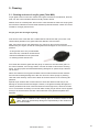
1. General Information
Thanks for purchasing a product of the Baumer family. This user´s guide explains how to
install cameras in a enclosure to protect your vision system and achieve IP 69 K protec-
tion.
Read this manual carefully and observe the notes and safety instructions!
Support
In case of any questions please contact our Technical & Application Support Center.
Worlwide: Baumer Optronic GmbH
Badstrasse 30
DE-01454 Radeberg, Germany
Tel: +49 (0)3528 4386 845
Website: www.baumer.com
E-mail: support.cameras@baumer.com
Target group for this User´s Guide
This user's guide is aimed at experienced users, which want to integrate camera(s) into
an enclosure.
Intended Use
The enclosure is used to protect a built-in camera in a production environment. Once the
camera is mounted in an enclosure, it can be easily adjusted and robustly installed on the
machine.
Notice
Use the enclosure only for its intended purpose!
For any use that is not described in the technical documentation poses dangers and will
void the warranty. The risk has to be borne solely by the unit´s owner.
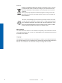
Classication of the safety instructions
In the user´s guide, the safety instructions are classied as follows:
Notice
Gives helpful notes on operation or other general recommendations.
Caution!
Pictogram
Indicates a possibly dangerous situation. If the situation is not avoided, slight
or minor injury could result or the device may be damaged.

4
Document Version: v1.0
Disposal
Dispose of outdated products with electrical or electronic circuits, not in the
normal domestic waste, but rather according to your national law and the
directives 2002/96/EC and 2006/66/EC for recycling within the competent
collectors.
Through the proper disposal of obsolete equipment will help to save valu-
able resources and prevent possible adverse eects on human health and
the environment.
The return of the packaging to the material cycle helps conserve raw mate-
rials an reduces the production of waste. When no longer required, dispose
of the packaging materials in accordance with the local regulations in force.
Keep the original packaging during the warranty period in order to be able
to pack the device properly in the event of a warranty claim.
Warranty Notes
If it is obvious that the device is / was reworked or repaired by other than Baumer techni-
cians, Baumer Optronic will not take any responsibility for the subsequent performance
and quality of the device!
Copyright
Any duplication or reprinting of this documentation, in whole or in part, and the reproduc-
tion of the illustrations even in modied form is permitted only with the written approval of
Baumer. The information in this document is subject to change without notice.

5
Document Version: v1.0
2. General Safety Instructions
Notice
Please observe the instructions and notes in the technical documentation of the camera
to be installed!
Caution
The suitability of the product for the users application with its specic condi-
tions of practice has to be tested and guaranteed by the user himself.
For special applications, please contact us in writing. We reserve the right to
make technical changes.
Caution
IP
Protection
Please follow these assembly guidelines carefully when assembling the en-
closures, as the IP protection rating stated may otherwise not be reached!
Caution
Inappropriate handling of the enclosure or any parts thereof may lead to a
leaky enclosure and may cause damage to the enclosed camera. Baumer
can take no liability for damages caused by improper handling.
Caution
The enclosures have been designed for a typical machine vision applica-
tion where the camera set-up is done once in order to build an application.
Frequent disassembly of the enclosure requires all seals and gaskets to be
renewed. Please order replacement seals or O-rings from Baumer when dis-
assembling the enclosure.
Caution
Baumer uses the best possible sealing materials for typical applications.
However every application is dierent - please check if our sealing material is
durable under the use intended.
Caution
Do not assemble the enclosure if any parts are damaged – this counts es-
pecially for the seals and sealing anges of the enclosure! In doubt – please
contact Baumer for advice.
Caution
Tighten the tube / rear wall as far as possible and don't use excessive force
in case it is not possible to screw the tube / rear wall completely down to the
metal middle housing part.

6
Document Version: v1.0
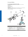
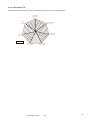
3. Housing Set Models
3.1 Housing Base Set B V4A VCXG.I r IP69K
▪ For lenses up to 55 mm diameter (52 mm front lid) and VCXG.I (.XT) cameras
▪ Stainless steel 1.4404
▪ Compact size
▪ Robust construction
▪ Vibration-proof mounting
▪ IP 69K rating
▪ Design according to EHEDG guidelines: Hygienic design with 3 mm radii (washdown
design) and hygienic surface (roughness < 0.8 μm, electropolished)
▪ Excellent heat dissipation
1
1
2
3
4
5
6
No. Description No. Description
1 Thermal pad 4 Handle
2 Clamp elements for VCXG.I
(.XT) camera
5 Rotation lock M40 V4A
IP69K (11208731), Optional
3 Housing Base Set B V4A VCXG.I
r IP69K
6 Tube M60 V4A IP69K Acryl (11208732)
mandatory, tube has to be ordered
seperately
Camera, lens and cables not included.


8
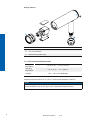
Document Version: v1.0
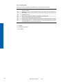
Sealing material
1
1
3
3
2
No. Material
1 Flouroprene
®
XP41
2 TPU - Polyurethane
3 EPDM O-Ring (inside only)
3.1.1 Environmental Requirements
Storage
temperature
-15 °C (-5 °F) ... +70 °C (+158 °F)
Operating
temperature
-15 °C (-5 °F) ... 70 °C (158 °F)
Humidity 10 % ... 90 % non condensing
Ambient temperature above 50 °C (122 °F) requires heat dissipation measures.
Notice
The housing improves the temperature management for the camera in use, the environ-
mental temperature may be 5 K higher than in applications without housing.

9
Document Version: v1.0
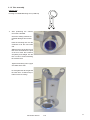
3.1.2 Clamp elements assembly
The mounting with clamp elements ensures exible camera positioning and good heat
dissipation. Follow these steps for a vibration proof camera positioning.
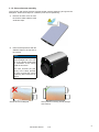
1. Remove the blue cover foil from
the double sided adhesive heat
conductive tape.
2. Place the clamp element with the
adhesive tape on the top side of
the camera.
Notice
The alignment of the clamp
ement (straight and in the cen-
tre of the camera) determines
the orientation of the camera
inside the enclosure.
The more accurate the posi-
tioning of the clamp element,
the more accurate the camera
positioning later inside the en-
closure.
Clamp element misaligned Clamp element correctly placed (straight
and centred)

10
Document Version: v1.0
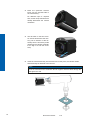
3. Place the quick-lock element
loose onto the opposite side of
the camera body.
No adhesive tape is required
here, as the clamp element block
already determines the camera
orientation.
4. The dot mark on the two eccen-
tric screws should face the cam-
era, prior to insertion of this as-
sembly into the enclosure prole
(otherwise the camera assembly
is too high to t into the enclo-
sure).
5. Insert the camera assembly into the enclosure. At this point, the camera cables
should already be attached to the camera.
Notice
The rubber cable gland seal insert can be mounted later – this makes it easier to
mount the camera into the enclosure! Do not forget to feed the cables though the
cable gland nut rst!

11
Document Version: v1.0
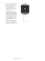
6. In order to secure the camera
assembly in position, turn the ec-
centric screw at the front clock-
wise or anti-clock-wise!
The clamp elements are fully ex-
tended, if the dot mark points to
the enclosure wall.
However, depending on the cam-
era tolerances, it might not be re-
quired to fully extend the clamp
elements – a quarter turn might
be sucient. A fastening torque
of 2Nm is sucient in order to
reach a clamping force of 900N,
so a rm but not excessive tight-
ening is recommended.
Position the lens so that it pro-
trudes no more than 23 mm from
the edge of the Housing Base
Set B, otherwise the tube will not
t!

12
Document Version: v1.0
3.1.3 Cable gland
Notice
The cable gland maintains the high IP68 rating if done carefully!
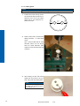
1. Position the holes evenly across
the seal insert with at least 2 mm
distance to the rim of the cable
gland and 3 mm distance be-
tween the holes.
at least
3 mm
at least
2 mm
at least
2 mm
2. Drill the holes with a vertical axis
drilling machine - no hand held
ones!
Use a normal HSS drill bit, with
diameter about 0,5 mm larger
than the cable diameter (this
makes an exact hole with the soft
material).
3. After drilling, slit the seal insert
radial from the holes to the out-
side, using a sharp cutting knife.
Notice
Do not use a sawing motion,
but rather cut straight through
for a cleaner cut.

13
Document Version: v1.0
4. Feed the cables through the nut
and the cable gland.
5. After cable and camera position-
ing insert the cables from the side
into the seal insert. These special
pliers are helpful – alternatively
use a screwdriver to open up the
cut in the cable gland seal.
Notice
Take care not to damage the
cable gland seal during this
process!
6. Push the seal insert with the ca-
bles into the cable gland.
Tighten the cable gland nut with
the recommended fastening
torque (15 Nm).
Caution
IP
Protection
Tighten the cable glands with the recommended fastening torque. Excessive
fastening torque may damage the sealing O-rings.
Insucient tightening torques may reduce the protective rating (i.e. from IP67
to IP54).

14
Document Version: v1.0
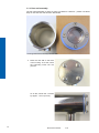
3.1.4 Rear wall assembly
The rear wall preparation is done ex works from Baumer. However – please note these
steps in case the rear wall has been dismantled.
Housing Base Set B with bayonet rear wall
1. Place the rear wall on the back
of the housing. To do this, insert
the protruding noses into the
grooves.
To do this, loosen the 4 screws
by approx. 1.5 mm (2 turns).

15
Document Version: v1.0
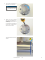
3. Turn the rear wall clockwise one
eighth turn (45°) until it stops.
Notice
If no stop is noticeable, then
you must tighten the screws a
little.
4. Tighten the screws crosswise
only so far that the light blue cov-
er seal is ush with the surface of
the housing.
Do not tighten the lid so tight that
the seal forms a bead and pro-
trudes over the housing!
Avoid gaps between seal and en-
closure!
!


17
Document Version: v1.0
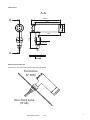
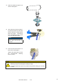
3.1.5 Tube assembly
Optional Tool
Housing V4A IP69K Mounting Tool (11208719)
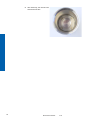
1. After positioning the camera,
mount the Tube M60.
Check the sealing surfaces for
possible damages and scratch-
es.
Feed the mounting tool over the
enclosure lid at the round hole
end.
Slide the tool over the lid in a way
that the it sits between the jaws
of the tool. Insert the enclosure
completely and straight into the
tool in order to avoid scratching
the enclosure lid!
Tighten the lid rmly until no gaps
are visible at the seal.
Do not tighten the lid so tight that
the seal forms a bead and pro-
trudes over the housing!

18
Document Version: v1.0
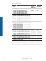
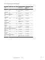
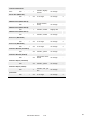
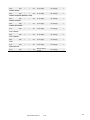
3.1.6 Approved cables
Article
number
Designation Smallest
bending
radius, xed
installation
Suitability @
lObj ≤ 50mm
VCXG.I(.XT)
11101979 Cable GigE M12X/RJ45, 5.0m 25.6 mm yes
11117630 Cable GigE M12X/RJ45, 10.0m
11117632 Cable GigE M12X/RJ45, 15.0m
11117633 Cable GigE M12X/RJ45, 20.0m
11185139 Cable GigE M12X/RJ45, 2.0m, STP, ex 35.34mm no
11195760 Cable GigE M12X/RJ45, 5.0m, STP, ex
11195761 Cable GigE M12X/RJ45, 10.0m, STP, ex
11195762 Cable GigE M12X/RJ45, 15.0m, STP, ex
11196995 Cable GigE M12X/RJ45, 20.0m, STP, ex
11185190 Cable GigE M12X/RJ45, 30.0m, STP, ex
11201118 ESG 34JP0200GS 30 mm yes
11195097 ESG 34JP0500GS
11195098 ESG 34JP1000GS
11195099 ESG 34JP2000GS
11201128 ESW 33JP0200GS
11195094 ESW 33JP0500GS
11195095 ESW 33JP1000GS
11195096 ESW 33JP2000GS
VCXG
11150185 Cable GigE RJ45s/RJ45, 5.0 m, chain 39.6 mm yes
11150302 Cable GigE RJ45s/RJ45, 10.0 m, chain
11150186 Cable GigE RJ45s/RJ45, 15.0 m, chain
11150188 Cable GigE RJ45s/RJ45, 20.0 m, chain
11173256 Cable GigE RJ45s/RJ45, 10.0m, ex v2 42 mm yes
11173257 Cable GigE RJ45s/RJ45, 20.0m, ex v2
11173258 Cable GigE RJ45s/RJ45, 30.0m, ex v2
11118810 Z-ESG 32FP0500G 29.5 mm yes
11138385 Z-ESG 32FP1000G
11105262 Z-ESW 31FH0500 25.5 mm yes
VCXU
11140628 KSG U2/KSGU6GV0300G 58 mm yes
11140627 KSG U2/KSGU6GV0500G 125 mm no

19
Document Version: v1.0
4. IP rating and chemical resistance
Caution
As a large number of chemical substances are used, we ask for your under-
standing that we can not test them all.
The chemical substances must be tested on an discreet area of the device
under application conditions to evaluate if they are suitable.
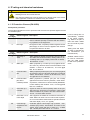
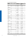
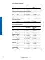
4.1 IP Protection Classes (EN 60529)
Solid particle protection
The rst digit indicates the level of protection that the enclosure provides against access
to harzadous parts.
Level
(1st digit)
Eective against Description
5 Dust protected Incress of dust is not entirely prevented, but it must not
enter in sucient quantity to interfere with the satisfac-
tory operation of the equipment.
6 Dust tight No ingress of dust; complete protection against contact
(dust thight). A vacuum must be applied. Test duration
of up 8 hours based on air ow.
Level
(2st digit)
Eective against Description
4 Splashing of
water
Water splashing against the enclosure from any direc-
tion shall have no harmfull eect, utilizing either: a) an
oscillating xture, or b) A Spray nozzle with no shield,
Test duration: 10 min.
5 Water jets Water projected by a nozzle (6.3 mm) against enclo-
sure from any direction shall no harmfull eects. Test
duration: 1 min/m² for at least3 min, 12.5 l/min @30
kPa at 3 m distance.
6 Powerful water
jets
Water projected powerful jets (12.5 mm nozzle) against
the enclosure from any direction shall have no harmful
eects. Test duration: 1 min/m² for at least 3 min, 100 l/
min @30 kPa at 3 m distance.
6K Powerful water
jets with in-
creased pressure
Water projected in powerful jets (6.3 mm nozzle)
against the enclosure from any direction, under elevat-
ed pressure, shall have no harmful eects (DIN40050,
not IEC 60529). Test duration: 3 min, 75 l/min @1000
kPa at 3 m distance.
7 Immersion up 1
m depth
Ingress of water in harmful quantity shall not be pos-
sible when the enclosure is immersed in water under
dened conditions of pressure and time Test duration:
30 min, 1 m below water surface.
8 Immersion 1 m or
more depth
The equipment is suitable for continuous immersion in
water. Water can enter in such a manner that it produc-
es no harmful eects. Manufacturer specied duration
and water depth (> IPx7, 3 m typical).
9K Powerful high
temperature wa-
ter jets
Protected against close-range high pressure / tem-
perature spray downs. Test duration: 30 s each of four
angles, spray nozzle with 80 °C water at 8 - 10 MPa
(80 - 100 bar) and a ow rate of 14 - 16 l/min.
Lower IP ratings are not
automatically included
in the higher classes,
e.g. IP66 is not part of
IP67 and IP68 / IP69K
do not include any other
ratings!
Testing time and depth
of IP68 is specied by
the manufacturer (not
unlimited time!).
Suitable cables have to
be used in combination
with the cable glands
to full the IP protection
class.

20
Document Version: v1.0
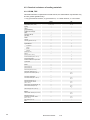
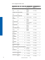
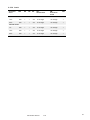
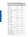
4.2 Chemical resistance of sealing materials
4.2.1 EPDM, TPE
This table hase been compiled from several sources, the classication may therefore vary
and is a general guideline only!
1 = very good chemical resistance; 2 = good resistance; 3 - 4 = limited resistance; 5 - 6 not resistant
EPDM TPE
temperature (min.; max.)
-40; 120 (150) -40; 130
ageing
1 1
ozone
1 1
gas permeability
suitable for food appl.
water
1 1
hot water (100 °C)
1
see water
2 1
steam
1
chlorine
3
chlorine (gaseous, 20 °C)
3 3
hydrocarbons:
5 2
mineral oil
5 2
petrol
5 3
diesel
3
alcohol
ethanol (20 °C)
1 1
ketone
2
aceton (100 %, 20 °C)
3
ammonia, diluted (10 %, 20 °C)
3
servo steering uids
5
break uids based on Glycol-ether
1 5
cyclohexane
Acids:
2
acetic acid 30 %
3
acetic acid 50 %
3
acetic acid (100 %, 20 °C)
5 2
silicic acid, diluted, (60 °C)
2
phosphoric acid, diluted (20 °C)
up to
85 % 2
nitric acid, conentrated
5
nitric acid, diluted (50 %, 20 °C)
3 up to
30 % 2
hydrochloric acid (20 °C)
2
hydrochloric acid, diluted
(30 %, 20 °C)
2 up to
10 % 1
sulfuric acid, concentrated (50 °C)
2
sulfuric acid, diluted (20 °C)
2 up to
98 % 1
citric acid (up to 10 %, 40 °C)
1 2
Bases:
2
caustic soda, diluted (10 %, 20 °C)
2 up to
50 % 2
bleaching lye (20 °C)
potassiuim hydroxide, diluted
(50 %, 20 °C)
5 up to
10 % 2
soap solution (20 °C)
1 1
suds
Page is loading ...
Page is loading ...
Page is loading ...
Page is loading ...
Page is loading ...
Page is loading ...
Page is loading ...
Page is loading ...
Page is loading ...
Page is loading ...
Page is loading ...
Page is loading ...
-
 1
1
-
 2
2
-
 3
3
-
 4
4
-
 5
5
-
 6
6
-
 7
7
-
 8
8
-
 9
9
-
 10
10
-
 11
11
-
 12
12
-
 13
13
-
 14
14
-
 15
15
-
 16
16
-
 17
17
-
 18
18
-
 19
19
-
 20
20
-
 21
21
-
 22
22
-
 23
23
-
 24
24
-
 25
25
-
 26
26
-
 27
27
-
 28
28
-
 29
29
-
 30
30
-
 31
31
-
 32
32


Baumer Clamp Elements CX 29 x 29 mm V4A IP69K User guide
- Type
- User guide
Ask a question and I''ll find the answer in the document
Finding information in a document is now easier with AI
Related papers
-
Baumer VCXG-32M.I Quick start guide
-
Baumer 8155 hygienic cable sensor Installation guide
-
Baumer VCXU-31C Quick start guide
-
Baumer VLXT-123M.FO Quick start guide
-
Baumer VCXU-31C Operating instructions
-
Baumer Housing V4A IP69K Mounting Tool Quick start guide
-
Baumer MXGC20c Quick start guide
-
-
-
Other documents
-
Emac NCA8912 User manual
-
Elenco EDU36734 Owner's manual
-
Trixie Alicante User manual
-
Unbranded WHT4497 Operating instructions
-
Vollrath Mounted Safety Guard Installation guide
-
 Mayser SL/NO Owner's manual
-
Kerbl 15325 Product information
-
Ti-SALES Ti User guide
-
First Alert LT1 Owner's manual
-
Mitsubishi Electric MAC 10 User manual
