Baumer VLXT-123M.FO Quick start guide

Category
Security camera accessories
Type
Quick start guide

This manual is also suitable for

Conformity / Safety
Further Information
For further information on our products visit www.baumer.com
For technical issues, please contact our technical support:
support.cameras@baumer.com · Phone +49 (0)3528 4386-0 · Fax +49 (0)3528 4386-86
© Baumer Optronic GmbH · Badstrasse 30 · DE-01454 Radeberg, Germany
Technical data has been fully checked, but accuracy of printed matter not guaranteed.
Subject to change without notice. Printed in Germany 10/20. v3 11214141
Quick Start Guide
VLXT.FO cameras (10 Gigabit Ethernet)
Download latest camera software:
www.baumer.com/vision/software
Download latest technical documentation:
www.baumer.com/cameras/docs
Product Specication
VLXT.FO cameras – Extremely functionality and high frame rates
Up to 12 megapixel and 216 fps
Power supply: 12 – 24 V ± 20 %
GigE Vision
TM
standard compliant
SFP+ (Enhanced small form-factor pluggable)
Optional: Protection class IP67 (with installed tube and Harting adapter)
Optional: Modular tube system
M12 industry connector
PWM on outputs for direct controlled illuminations
4 outputs with maximum 1.5 A (2.5 A with 40% periode time)
Notice
Further technical details are available in the respective data sheets.
Dimensions
79,6 ±0,3
12,9
5,5
8,33
26
26
8,33
7,83
68,5
26
15,7
15,7
19,6
18,2
M3 x 5/78 x
M3 x 5/72 x
temperature
measurement point
35
35
M3 x 6/8
4 x
Pixel 0,0
1/4"-20 UNC x 6/9
28,7Ø
6,4
C-Mount
Installation
Modular tube system and Harting Adapter (ordered separately)
Do not forget the seals!
Recommended grease
for easier installation:
ELKALUB GLS 867
Tube
Tube Adapter
Camera
Distance Ring
The peak torque while
tightening the
screws is 0.9 Nm.
Use a torque wrench!
Harting Adapter
The peak torque while
tightening the
screws is 0.9 Nm.
Use a torque wrench!
Conformity
We declare, under our sole responsibility,
that the previously described Baumer VLXT.
FO cameras conform with the directives of
the CE.
All VLXT.FO cameras complies with the
recommendation of the European Union
concerning RoHS Rules.
U
L
US
LISTED
C
The camera has been tested by UL (Under-
writers Laboratories) and complies with the
requirements of the standards.
Please see the User’s Guide for further
information.
Safety Precautions
Notice
See the User's Guide for the complete safety
instructions!
Caution
Observe precautions for handling
electrostatically sensitive devices!
Environmental Requirements
Storage temp. -10 °C ... +70 °C
Humidity 10 % ... 90 %
Non-condensing
System Requirements
Recommended for
GigE
Recommended for
10 GigE
CPU Intel
®
Core
i5-2520M
CPU @ 2.50 GHz, Cores: 4
Intel
®
Core
i7-3770
CPU @ 3.40 GHz, Cores: 8
RAM 4 GB 8 GB
Oper-
ating
system
(OS)
Microsoft
®
Windows
®
7 (32 / 64 bit systems)
Microsoft
®
Windows
®
8 (32 / 64 bit systems)
Microsoft
®
Windows
®
10 (32 / 64 bit systems)
Installation
Lens mount
Notice
Ensure the sensor and lens are not contaminated with dust and airborne particles
when mounting the support or the lens to the device!
The following points are very important:
Install the camera in an environment that is as dust free as possible!
Keep the dust cover (bag) on the camera for as long as possible!
Hold the camera with the sensor downwards if the sensor is uncovered.
Avoid contact with any of the camera‘s optical surfaces!
LED Signaling
2
1
LED Signal Meaning
1 GigE LED
green static link active
green ash receiving
2 Camera LED
yellow static error
yellow ash transmitting
orange static overheated
General Description
146
7
2 53
No. Description No. Description
1 Lens mount (C-mount) 5 GigE LED
2 Lens control (≥ Release 3 only) 6 Camera LED
3
4 x Tube Adapter /front mount-
ing threads
7 SFP+ Socket
4 Power- and process interface
Heat Transmission
Caution
Heat can damage the camera. Ambient temperature above 25 °C (77 °F)
requires heat dissipation measures. Provide adequate dissipation of heat,
to ensure that the temperatures does not exceed the specied values.
Baumer recommends the following methods for proper heat dissipation:
Every form of convection around the device and mounting helps reduce
temperature. Prevent heat from becoming trapped!
Mounting in combination with forced convection may provide proper
heat dissipation.
Avoid mounting onto stainless steel. Stainless steel has a roughly 10-
fold lower thermal conductivity compared to aluminium.
Do not install the device at the end of a profile; this will allow heat to
dissipate on both sides (higher temperature drops over a larger area)!
Do not operate other devices in close proximity to the camera. Their
waste heat could additionally heat the camera.
From an ambient temperature of 30 °C (86 °C) up to +40 °C (104 °F)
the camera requires forced air cooling (min. 0.9 m/s).
T
See User´s Guide for further information.
Data Interface
SFP+ Socket
8
9
10
11
12
5
7
3
1
4
2
6
13
14
15
16
17
18
19
20
1 VEET 11 VEER
2 TX_FAULT 12 RD-
3 TX_DISABLE 13 RD+
4 SDA 14 VEER
5 SCL 15 VCCR
6 MOD_ABS 16 VCCT
7 RS0 17 VEET
8 RX_LOS 18 TD+
9 RS1 19 TD-
10 VEER 20 VEET
Power Supply
Power Supply
Power V
CC
12 V ... 24 V (-15 % ... + 20 %) / Power consumption: max. 9.6 W
For UL conform installation:
Class 2 per NEC / Protection Class III
The device is intended to be supplied from an isolated Limited Ener-
gy Source per UL61010-1, 3rd ed cl. 9.4 or Limited Power Source
per UL60950-1 or Class 2 per NEC.
Digital IOs
Power supply / Digital IOs (on camera side)
(SACC-CI-M12MS-12CON-L180)
M12 / 12 pins / wire colors of the connecting cable (ordered separately)
8
9
10
11
12
5
7
3
1
4
2
6
1 Power V
CC
brown
7 OUT3 (Line6) black
2 GND (Power) blue
8 RS232 Txd (Line2) grey
3 IN1 (Line0) white 9 OUT4 (Line7) red
4 OUT1 (Line4) green 10 RS232 RxD (Line3) violet
5 IN2 (Line1) pink 11 GND (IO) grey-pink
6 OUT2 (Line5) yellow 12 Power (IO) red-blue
Caution
IP
Protection
In order to achieve the mentioned IP protection level, the M12 connector
need to be tightened with a torque value of 0.4 Nm.
For that Baumer suggests the use of a torque driver (such as Wiha Tor-
queVario
®
-S ESD) in combination with a wrench for assembling sensor/
actuator cables with M12 connector (such as Phoenix Contact SAC BIT
M12-D15).
On the SFP+ socket, a Harting Adapter must be used.
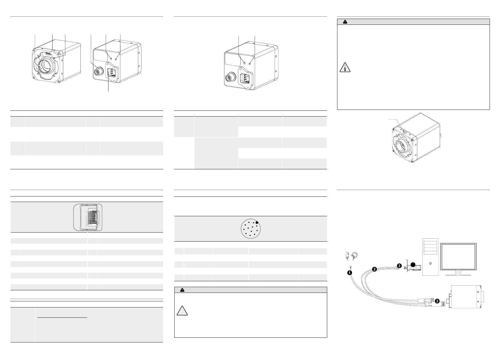
Installation
Installation of the camera:
Connect the camera using appropriate fibre optic cables to the transceivers.
If required, connect a trigger and / or flash to process interface.
Connect the camera to power supply.
open wire
4
Installation sample
1 - Cable for trigger and ash
2 - Optical Fibre cables
3 - SFP+ Transceiver
4 - PCI board
  • Page 1 1
  • Page 2 2

Baumer VLXT-123M.FO Quick start guide

Category
Security camera accessories
Type
Quick start guide
This manual is also suitable for

Ask a question and I''ll find the answer in the document

Finding information in a document is now easier with AI