Page is loading ...

H
G
I
J
K
L
M
IMPORTANT : Fixture should be installed by a qualified
electrician to ensure proper wiring and installation.
Dimmable with C-L (CFL & LED) type and
Incandescent/Halogen type dimmers
INSTALLATION INSTRUCTIONS FOR P951-084-L
For LED Pendant
WARNING! SHUT POWER OFF AT FUSE OR CIRCUIT BREAKER.
AV E R T I S S E M E N T ! CO U P E R L E C O U R A N T AU N IV E A U DE S F U S I B L E S O U D O DI S J O N C T EU R .
PREPARATION
1. Shut off power at the fuse box or circuit breaker box. If
necessary remove the old fixture and mounting hardware.
2. Carefully unpack your new fixture and lay out all the parts
on a clear area. Take care not to lose any small parts
necessary for installation.
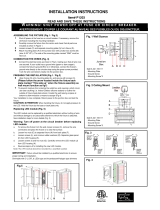
MOUNTING THE FIXTURE (FIG. 1)
3. Secure mounting back plate (B) to junction box (A) using
junction boxes screws (C) (Size: 8-32*1/2”L). The side of
the mounting back plate marked “GND” must face out.
4. Press tube (I) to adjust the power cable and support cables
(J) to the desired hanging height. Cut and discard excess
power cable and support cable (J). Note: Leave 7”-10” of
extra power cable to allow for electrical connection.
CONNECTING THE WIRES (FIG. 2)
5. At this point, connect the electrical wires as shown in Fig. 2,
making sure that all wire connectors are secured. If your
outlet has a ground wire (green or bare copper), connect
the fixtures ground wire to it. Otherwise, connect the fixture
ground wire directly to the back plate (B) using the green
screw (E) provided. After wires are connected, tuck them
carefully inside the junction box.
FINISHING THE INSTALLATION (FIG.1)
6. Align the fixture’s back plate (G) over the mounting back
plate (B) and secure with screws (H).
CAUTION /ATTENTION: When handling the fixture, do not
apply pressure to the LEDs.
Replacing LED module (Fig. 3)
The LED module can be replaced by a qualified electrician
without cutting of wire and without damage to any decorative
element to which the fixture is attached. See installation steps
for more details (Fig 3.)
a. Shut off the power. Remove finial (M) and acrylic shade (L).
b. Remove screws (K) and carefully disconnect the quick
connector on the LED module.
c. Remove LED module (J) from back plate (I).
d. Reverse steps a-c for installing the new LED module.
e. Note: The LED module should be provided by a specified
supplier.
f. For better heat dissipation the LED module (J) should be
applied with thermal grease when re-lamping.
Brand : Lutron
Brand : Leviton / Model number : Sureslide 6615
Fig 3
H
G
I
J
K
L
M
Fig.2
FIXTURE
WIRES
Black or
Smooth
HOUSE
WIRES
Black
(Hot)
FIXTURE
WIRES
White or
Ribbed
HOUSE
WIRES
White
(Neutral)
FIXTURE
WIRES
Bare
Copper
(Ground)
HOUSE
WIRES
Green or
Bare
Copper(G
round)
I
FIG.1
A
B
C
D
F
H
E
G
White wire
Black wire
Set A# A-021-153D
Back plate
Green screw
Mounting Screws(2)
Set A# A-021-153D
Back plate
Green screw
Mounting Screws(2)
J
I
/