Page is loading ...

INSTALLATION INSTRUCTIONS
FOR P1387-077-L, P1388-077-L, P1389-077-L
FOR LED PENDANT LIGHT
WARNING! SHUT POWER OFF AT FUSE OR CIRCUIT BREAKE R.
AV E R T I SS E ME N T ! C O U P E R LE C O U R A N T A U N I V E A U D E S F US IB L E S OU D O DI S J O N C T E U R
Page: 1/3
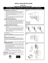
Fig. 2
HANGING THE FIXTURE
1. Carefully remove the fixture from the carton and check
that all parts are included as shown in the illustration.
2. Shut off power at the circuit breaker and remove old
fixture including the mounting hardware
SUGGESTED INSTALLATION (Fig. 1&3)
3. Attach the mounting plate (B) to the junction box (A)
using screws (C) (Screw Size: 8-32*1/2”L). The side of
the mounting plate marked “GND” must face out.
4. Determine length desired and thread rods (F1,F2,F3)
to housing (N), then place the canopy (G) over the rod
(F1) and connect swivel (D) to rod (F1). Meanwhile,
carefully pass the fixture wires through rod and swivel.
Note: Please remove the nipple if use one 3” rod (F3)
only.
CONNECTING THE WIRES (Fig. 1&2)
5. Cut the extra wire if necessary. Connect the driver
output wires (Red to Red; and Black to black) with
fixture, making sure that all wires connectors (O) are
secured.
6. Connect the driver input wire with housing wire as
shown in Fig.2, making sure that all wire connectors
(P) are secured.
7. If your outlet box has a green or bare copper ground
wire, connect the fixture’s ground wire to it. Otherwise,
connect the fixture’s ground wire directly to the
mounting plate (B) using the green screw provided.
After wires are connected, tuck them carefully inside
the junction box (A).
COMPLETING THE INSTALLATION (Fig. 3)
8. Connect the canopy with the mounting plate (B) and
secure with mounting screws (E).
9. Align the glass (I) to the housing (N), make sure the
hole on the glass match the hole, and tighten it with
screws (F).
For slope ceiling application, rotate swivel at the top of
the stem to ensure luminaries is aiming down (Fig. 3).
Your installation is now complete. Return power to the
junction box and test the fixture.
CAUTION /ATTENTION: When handling bracket, do not
apply pressure to the LEDs. Hold the metal parts.
Fig.1
P1387, P1388 Set# A-021-135
P1389 Set#: A-021-195
- Mounting plate
- Ground screw
- Mounting screws*2pcs
FIXTURE
WIRES
Black or
Smooth
HOUSE
WIRES
Black
(Hot)
FIXTURE
WIRES
White or
Ribbed
HOUSE
WIRES
White
(Neutral)
FIXTURE
WIRES
Bare
Copper
(Ground)
HOUSE
WIRES
Green
(Ground)

Fig.3
Hardware Bag:
P1387, P1388
F1.Rod 12”*1 Rod# W30-1-077
F2.Rod 12”*2 Rod# W30-1-077
F3.Rod 3” *2 Rod# W30-3-077
P1389
F1.Rod 12”*1 Rod# W35-1-077
F2.Rod 12”*2 Rod# W35-1-077
F3.Rod 3” *2 Rod# W35-3-077
Fig.4 Fig.4
Page: 2/3
IMPORTANT: Fixture should be installed by a
qualified electrician to ensure proper wiring and
installation.
Dimmable with ELV and/or LED compatible wall
dimmer switches.
.
Replacing LED module (Fig. 4)
The LED module can be replaced by a qualified
electrician without cutting of wire and without
damage to any decorative element to which the
fixture is attached. See installation steps for
more details (Fig.4.)
a. Shut off power. Take off the glass (I) by
loosen screws (F).
b. Use a pin to stick the hole on the quick
connector (J) to disconnect the wire.
c. Remove screws (H) on the PCB to
disconnect the LED module (K).
d. Reverse steps a-c for installing the new
LED module.
e. Note: The LED module should be provided
by a specified supplier.

INSTALLATION INSTRUCTIONS
FOR P1387-077-L, P1388-077-L, P1389-077-L
FOR LED SEMI-FLUSH
WARNING! SHUT POWER OFF AT FUSE OR CIRCUIT BREAKE R.
AV E R T I SS E ME N T !
Page: 3/3
Fig. 2
HANGING THE FIXTURE
1. Carefully remove the fixture from the carton and check
that all parts are included as shown in the illustration.
2. Shut off power at the circuit breaker and remove old
fixture including the mounting hardware
SUGGESTED INSTALLATION (Fig. 5)
3. Attach the mounting plate (B) to the junction box (A)
using screws (C) (Screw Size: 8-32*1/2”L). The side of
the mounting plate marked “GND” must face out.
4. Thread one rod (F3) only to the housing (N), and
remove nipple on rod (F3) and then place the canopy
(G) over the rod (F3) and connect swivel (D) to rod
(F3). Meanwhile, carefully pass the fixture wires
through rod and swivel.
CONNECTING THE WIRES (Fig. 2&5)
5. Cut the extra wire if necessary. Connect the driver
output wires (Red to Red; and Black to black) with
fixture, making sure that all wires connectors (O) are
secured.
6. Connect the driver input wire with housing wire as
shown in Fig.2, making sure that all wire connectors
(P) are secured.
7. If your outlet box has a green or bare copper ground
wire, connect the fixture’s ground wire to it. Otherwise,
connect the fixture’s ground wire directly to the
mounting plate (B) using the green screw provided.
After wires are connected, tuck them carefully inside
the junction box (A).
COMPLETING THE INSTALLATION (Fig. 5)
8. Connect the canopy (G) with the mounting plate (B)
and secure with mounting screws (E).
9. Align the glass (I) to the housing (N), make sure the
hole on the glass match the hole, and tighten it with
screws (F).
For slope ceiling application, rotate swivel at the top of
the stem to ensure luminaries is aiming down (Fig. 5).
Your installation is now complete. Return power to the
junction box and test the fixture.
CAUTION /ATTENTION: When handling bracket, do not
apply pressure to the LEDs. Hold the metal parts.
Fig.5
P1387, P1388 Set# A-021-135
P1389 Set#: A-021-195
- Mounting plate
- Ground screw
- Mounting screws*2pcs
FIXTURE
WIRES
Black or
Smooth
HOUSE
WIRES
Black
(Hot)
FIXTURE
WIRES
White or
Ribbed
HOUSE
WIRES
White
(Neutral)
FIXTURE
WIRES
Bare
Copper
(Ground)
HOUSE
WIRES
Green
(Ground)
/