Page is loading ...

585-300-122
Comcode 108473489
Issue 1
May 1999
Installation and Switch Administration
for the
DEFINITY
®
AUDIX
®
System
Release 4.0
G3i/G3s/G3vs/R5vs/R5si/ProLogix switches
TN2181 emulation
Display Set Integration

Copyright 1999, Lucent Technologies
All Rights Reserved, Printed in U.S.A.
Notice
Every effort was made to ensure that the information in this book was
complete and accurate at the time of printing. However, information is
subject to change.
Your Responsibility for Your System’s Security
Toll fraud is the unauthorized use of your telecommunications system
by an unauthorized party, for example, persons other than your com-
pany’s employees, agents, subcontractors, or persons working on your
company’s behalf. Note that there may be a risk of toll fraud associated
with your telecommunications system and, if toll fraud occurs, it can
result in substantial additional charges for your telecommunications
services.
You and your system manager are responsible for the security of your
system, such as programming and configuring your equipment to pre-
vent unauthorized use. The system manager is also responsible for
reading all installation, instruction, and system administration docu-
ments provided with this product in order to fully understand the fea-
tures that can introduce risk of toll fraud and the steps that can be taken
to reduce that risk. Lucent Technologies does not warrant that this
product is immune from or will prevent unauthorized use of com-
mon-carrier telecommunication services or facilities accessed through
or connected to it. Lucent Technologies will not be responsible for any
charges that result from such unauthorized use.
Lucent Technologies Fraud Intervention
If you suspect you are being victimized by toll fraud and you need
technical support or assistance, call the appropriate BCS National Cus-
tomer Care Center telephone number. Users of the MERLIN®, PART-
NER®, and System 25 products should call 1 800 628 2888. Users of
the System 75, System 85, DEFINITY® Generic 1, 2 and 3, and
DEFINITY® ECS products should call 1 800 643 2353. Customers
outside the continental United States should contact their local Lucent
representative, or call one of the above numbers in the following man-
ner:
• Dial the International Access Code; for example, 011.
• Dial the country code for the U.S., that is, 01.
• Lastly, dial either of the telephone numbers provided above.
Lucent Technologies Web Page
The world wide web home page for Lucent Technologies is:
http://www.lucent.com
Federal Communications Commission Statement
Part 15: Class A Statement. This equipment has been tested and
found to comply with the limits for a Class A digital device, pursuant
to Part 15 of the FCC Rules. These limits are designed to provide rea-
sonable protection against harmful interference when the equipment is
operated in a commercial environment. This equipment generates,
uses, and can radiate radio-frequency energy and, if not installed and
used in accordance with the instructions, may cause harmful interfer-
ence to radio communications. Operation of this equipment in a resi-
dential area is likely to cause harmful interference, in which case the
user will be required to correct the interference at his own expense.
Industry Canada (IC) Interference Information
This digital apparatus does not exceed the Class A limits for radio
noise emissions set out in the radio interference regulations of Industry
Canada.
Le Présent Appareil Nomérique n’émet pas de bruits radioélectriques
dépassant les limites applicables aux appareils numériques de la class
A préscrites dans le reglement sur le brouillage radioélectrique édicté
par le Industrie Canada.
Trademarks
See the preface of this document.
Ordering Information
Call: Lucent Technologies BCS Publications Center
Voice 1 800 457-1235 International Voice 317 322-6791
Fax 1 800 457-1764 International Fax 317 322-6699
Write: Lucent Technologies BCS Publications Center
2855 N. Franklin Road
Indianapolis, IN 46219
Order: Document No. 585-300-122
Comcode 108473489
Issue 1, May 1999
For additional documents, refer to the section in “About This Docu-
ment” entitled “Related Resources.”
You can be placed on a standing order list for this and other documents
you may need. For more information on standing orders, or to be put on
a list to receive future issues of this document, contact the Lucent Tech-
nologies Publications Center.
Obtaining Products
To learn more about Lucent Technologies products and to order prod-
ucts, contact Lucent Direct, the direct-market organization of Lucent
Technologies Business Communications Systems. Access their web
site at www.lucentdirect.com. Or call the following numbers: custom-
ers 1 800 451 2100, account executives 1 888 778 1880 (voice) or 1
888 778 1881 (fax).
Warranty
Lucent Technologies provides a limited warranty on this product. Refer
to the “Limited Use Software License Agreement” card provided with
your package.
European Union Declaration of Conformity
The “CE” mark affixed to the equipment means that it conforms to the
following directives. Lucent Technologies Business Communications
Systems declares that DEFINITY AUDIX System equipment specified
in this document conforms to the referenced European Union (EU)
Directives and Harmonized Standards listed below:
EMC Directive 89/336/EEC
Low-Voltage Directive73/23/EEC
Acknowledgment
This document was prepared by OMD Technical Publications, Lucent
Technologies, Denver, CO. and Columbus, OH.

Installation and Switch Administration for G3i/G3s/G3vs/R5vs/R5si/ProLogix
Switches, TN2181 Emulation, Display Set Integration
585-300-122
Issue 1
May 1999
Contents
iii
Contents
Contents iii
About This Document xi
■ Overview xi
■ Intended Audiences xi
■ Prerequisite Skills and Knowledge xii
■ Trademarks and Service Marks xii
■ Organization of This Document xii
■ How to Use This Document xiv
■ Conventions Used in This Document xiv
■ Related Resources xv
■ How to Get Help xvi
■ How to Make Comments About This Document xvi
1 Prerequisites 1-1
■ Display Set and Control-Link Integration 1-1
Task 3-1: Verify the Selected Site 1-2
Task 3-2: Gather the Required Tools 1-2
Task 3-3: Review Safety Considerations 1-3
Task 3-4: Verify the Components and Connectivity 1-3
Task 3-5: Complete the Worksheets 1-6
2 Hardware Installation 2-1
■ Worksheets Needed 2-1
Task 4-1: Install the DEFINITY AUDIX System Assembly 2-2
Slot and Carrier Restrictions 2-4
DEFINITY AUDIX System Slots 2-4
Installation Steps 2-5
Task 4-2: Connect to the System Adaptor Cable 2-9
Alarm Origination/Remote Access Connection 2-9
LAN Connection 2-11
Port Connections for DS Integration 2-13

Installation and Switch Administration for G3i/G3s/G3vs/R5vs/R5si/ProLogix
Switches, TN2181 Emulation, Display Set Integration
585-300-122
Issue 1
May 1999
Contents
iv
Task 4-3: Install the Terminals 2-13
3A: Installing a Terminal via Direct Connection 2-14
3B: Installing an Additional Administration
Terminal via Modem 2-16
3C: Installing an Additional Administration
Terminal via Asynchronous Data Units (ADUs) 2-19
3D: Installing an Additional Administration
Terminal via 7400A Data Modules 2-21
Task 4-4: Install the Printer (Optional) 2-24
Task 4-5: Finalize and Test the Hardware 2-25
3 Definity AUDIX Option Administration 3-1
■ Worksheets Needed 3-1
■ Dual Administration on the 715 Terminal 3-1
■ DEFINITY AUDIX Function Keys 3-2
Task 5-1: Activate Customer Options 3-3
4 Initial Switch Administration:
G3i/G3s/G3vs/R5vs/R5si/ProLogix 4-1
■ Worksheets Needed 4-1
■ What You Must Know Before You Begin This Chapter 4-2
■ Translation Overview Tables 4-2
■ Administration Overview 4-4
Native Mode of the Switch 4-4
Digital Networking Availability 4-5
Summary of Integrations, Emulations, and Capacities4-5
■ TN2181 (Digital Port) Emulation,
Display Set Integration 4-6
Task 6-1: Identifying the DEFINITY AUDIX Circuit Pack 4-6
Task 6-2: Creating the Hunt Group 4-9
Task 6-3: Defining the Call Coverage Path for
Voice Ports 4-14
Task 6-4: Defining Call Coverage Paths for Subscribers 4-16
Task 6-5: Administering the Voice Ports as Stations 4-19
Rules for Administering the Voice Ports 4-19
5A: Completing the Station Screen 4-19
5B: Assigning the Call Appearance
Buttons 4-28
5C: Assigning the Feature Buttons 4-31
5D: Assigning the Display Buttons 4-31
5E: Duplicating the Stations 4-32

Installation and Switch Administration for G3i/G3s/G3vs/R5vs/R5si/ProLogix
Switches, TN2181 Emulation, Display Set Integration
585-300-122
Issue 1
May 1999
Contents
v
Task 6-6: Assigning Voice Ports to the Hunt Group 4-33
Task 6-7: Administering the Digital
Networking Port (Optional) 4-35
5 Initial Definity AUDIX Administration 5-1
■ Worksheets Needed 5-1
Task 7-1: Perform Initial DEFINITY AUDIX Administration 5-2
1A: Set the DEFINITY AUDIX Clock 5-2
1B: Assign the Time Zone 5-4
1C: Assign the DEFINITY AUDIX
Machine Parameters 5-6
1D: Run the Switch Translations Audit 5-7
1E: Administer Voice Ports 5-8
1F: Set Switch-Link Parameters 5-10
1G: Set System Parameters Limits 5-11
1H: Set System Parameters for
I
NTUITY Message Manager 5-12
1I: Reboot the DEFINITY AUDIX System 5-14
1J: Run the Switch Names Audit 5-16
Task 7-2: Activate Parameters and Basic Features 5-17
Task 7-3: Add Magneto-Optical Disks 5-19
Task 7-4: Check the Status of the
Switch Names Audit 5-21
Task 7-5:
Check Alarm Status 5-24
6 Optional Switch Feature Administration 6-1
■ Worksheets Needed 6-2
■ Automated Attendant Administration 6-2
Generic 3, Version 2 and Greater Switches 6-2
Assigning a Phantom Station 6-2
Assigning a Hunt Group 6-3
Night Service to an Automated Attendant 6-3
From an Incoming Trunk 6-4
From a Listed Directory Number (LDN) 6-4
■ Automated Attendant Substitute Strategies 6-5
Generic 3, Release 5, and Newer Switches 6-5
■ Switch Recorded Announcement 6-6
■ Switch Multiple Coverage Paths 6-8
■ Listed Directory Number (LDN) Night Destination 6-8
■ Continue with the Installation 6-8

Installation and Switch Administration for G3i/G3s/G3vs/R5vs/R5si/ProLogix
Switches, TN2181 Emulation, Display Set Integration
585-300-122
Issue 1
May 1999
Contents
vi
7 Joint Acceptance Testing 7-1
■ Acceptance Check Tasks 7-1
■ Worksheets Needed 7-1
Task 9-1: Add Two Test Subscribers 7-2
Task 9-2: Test the Call Answer and
Voice Mail Features 7-3
Task 9-3: Run Test MO-Disk 7-4
Task 9-4: Test The Local Area Network 7-6
Task 9-5: Clear Administration, Error, and Alarm Logs 7-8
8 Initial Subscriber Administration 8-1
■ Initial Subscriber Administration Tasks 8-1
■ Worksheets Needed 8-1
Task 10-1: Optimize the Class of Service (COS) Values 8-2
Task 10-2: Add the Initial Subscribers 8-3
Task 10-3: Complete Initial Administration 8-5
9 Final Switch Administration:
G3i/G3s/G3vs/R5vs/R5si/ProLogix 9-1
Task 11-1: Modifying the Station
Screen for Each Subscriber 9-1
10 Customer Acceptance 10-1
Task 12-1: Alarm Origination Administration
Test and Status MO Disk 10-1
Task 12-2: Perform a Walk Through 10-5
Task 12-3: Demonstrate Updated Customer Database 10-5
Task 12-4: Project Review 10-5
A Switch Carrier Configuration Worksheets A-1
Worksheet A-1: Port Slot Assignments
(Before Carrier Rearrangement) A-2
Worksheet A-2: Port Slot Assignments
(For Carrier Rearrangement) A-4
Worksheet A-3: Slot Locations for
the DEFINITY AUDIX System Assembly A-5

Installation and Switch Administration for G3i/G3s/G3vs/R5vs/R5si/ProLogix
Switches, TN2181 Emulation, Display Set Integration
585-300-122
Issue 1
May 1999
Contents
vii
B Switch Administration Worksheets B-1
Worksheet B-1: Administer the Voice
Ports as Stations (Digital Port Emulation) B-2
Worksheet B-2: Assign the Hunt
Group (Digital Port Emulation) B-5
Worksheet B-3: Assign the Call Coverage Path
for Voice Ports (Digital Port Emulation) B-8
Worksheet B-4: Assign the Call Coverage Path
for Subscribers (Digital Port Emulation) B-9
Worksheet B-16: Administer Digital
Networking Ports (Digital Port Emulation) B-10
Worksheet B-19: Administer a Modem
– Digital Networking B-11
C DEFINITY AUDIX System
Administration Worksheets C-1
Worksheet C-1: Activate Customer Options C-2
Worksheet C-2: Activate IMAPI for the
AUDIX Server Hardware (LAN) Options C-3
Worksheet C-3: Assign the DEFINITY
AUDIX Machine ID C-5
Worksheet C-5: Set System Parameters Limits C-6
Worksheet C-6: Assign the Time Zone C-7
Worksheet C-7: Activate Parameters
and Basic Features C-8
Worksheet C-8: Add Subscribers C-11
Worksheet C-9: Set Up Alarm Origination C-14
D Optional Features Worksheets D-1
Worksheet D-1: Administering AMIS
Analog Networking and Message Delivery D-1
Worksheet D-2: Automated Attendant D-5
Worksheet D-3: Administering a Bulletin Board D-8
Worksheet D-4: Administering Outcalling D-9
Worksheet D-5: Administering Switch
Recorded Announcement D-10
E Terminal Configuration E-1
Worksheet E-1: Terminals E-1

Installation and Switch Administration for G3i/G3s/G3vs/R5vs/R5si/ProLogix
Switches, TN2181 Emulation, Display Set Integration
585-300-122
Issue 1
May 1999
Contents
viii
F Migration Procedure F-1
■ Materials and Information Needed F-2
■ Migration Checklist F-3
Task F-1: Shut Down the DEFINITY AUDIX System F-3
Task F-2: Export the Switch Voice Ports F-4
Task F-3: Remove the Voice Ports from the Hunt Group F-5
Task F-4: Connect the External
Tandberg Tape Drive F-6
Task F-5: Back-Up the DEFINITY AUDIX Data F-7
Task F-6: Remove the Existing
DEFINITY AUDIX System F-12
Task F-7: Install DEFINITY AUDIX 4.0 F-13
Task F-8: Restore the Existing Data F-17
Task F-9: Remove the Tape Drive F-20
Task F-10: Verify the DEFINITY AUDIX Administration F-20
10A: Display Customer Options F-20
10B: Verify the Voice Port Configuration F-22
10C: Verify the Subscribers F-23
Task F-11: Administer Changes to the Switch F-23
11A: Determine the Number of Voice Ports F-23
11B: Administer the Voice Port Station Screen F-24
11C: Add Voice Ports Back to the Hunt Group F-27
Task F-12: Complete Additional Migration Tasks F-29
G Announcement Set Considerations
and Installation G-1
■ Customized Announcement and
Fragments G-1
Customer Modified and Added Fragments G-1
Announcement Set Identifiers G-1
■ Installing Additional Language Sets G-3
H Terminal and Modem Settings H-1
■ Terminal Option Settings H-1
■ Modem Option Settings (for Port C Modems) H-5
US Robotics Sportster 33.6 H-5
Paradyne Comsphere Models 3810 and 3820 H-6
Paradyne Comsphere Model 3910 H-6
Generic Modems H-7

Installation and Switch Administration for G3i/G3s/G3vs/R5vs/R5si/ProLogix
Switches, TN2181 Emulation, Display Set Integration
585-300-122
Issue 1
May 1999
Contents
ix
7400A Data Module Settings H-10
7400B Data Module Settings H-10
I Changing Switch Integrations, Port
Emulations, and Number of Voice Ports I-1
■ Changing from Analog to Digital Port
Emulation I-1
Verifying the Emulation and Integration Types I-1
Verifying the DEFINITY AUDIX TN568 Circuit Pack I-2
Administering the Voice Ports I-2
Changing the Hunt Group I-2
Adding the Voice Port Coverage Path I-2
■ Changing from CL Integration —
Analog to DS Integration — Digital I-3
Verifying the Emulation and Integration Types I-3
Removing Voice Ports I-4
Verifying the Port IDs of the Voice Ports I-4
Removing Existing Voice Ports I-5
Verifying the Circuit Pack I-6
Administering the Voice Ports I-7
Changing the Hunt Group I-7
Adding the Voice Port Coverage Path I-8
Changing Subscriber Stations I-8
Disabling the Data Link I-8
■ Changing from DS Integration —
Digital to CL Integration — Digital I-9
Turning Off Message Waiting Indicators I-9
Verifying the Emulation and Integration
Types I-10
Verifying the Circuit Pack I-11
Re-administering the Voice Ports I-11
Changing the Hunt Group I-11
Assigning the Data Link I-11
Changing Subscriber Stations I-12
Checking the Switch Link I-12

Installation and Switch Administration for G3i/G3s/G3vs/R5vs/R5si/ProLogix
Switches, TN2181 Emulation, Display Set Integration
585-300-122
Issue 1
May 1999
Contents
x
■ Decreasing the Number of Digital Voice Ports
from 12 to 8 I-13
Changing the Voice Group Screen on the
DEFINITY AUDIX System I-13
Verifying DEFINITY AUDIX Customer Options I-13
Add a Networking Port I-14
Removing Ports from the Hunt Group I-14
Removing Voice Ports I-16
J Analog Port Administration J-1
■ G3i/G3s/G3vs/R5si/R5vs J-1
Task J-1: Identifying the Circuit Pack
— Analog Emulation J-1
Task J-2: Administering the Voice Ports as Stations J-3
2A: Completing the Station Screen J-4
2B: Duplicating the Station J-7
2C: Assigning the Hunt Group J-8
AB Abbreviations AB-1
GL Glossary GL-1
IN Index IN-1

About This Document
xiOverview
Installation and Switch Administration for G3i/G3s/G3vs/R5vs/R5si/ProLogix
Switches, TN2181 Emulation, Display Set Integration
585-300-122
Issue 1
May 1999
About This Document
Overview
This document describes the following procedures:
■ Installation of DEFINITY
®
AUDIX
®
Voice Messaging System release 4,
version 0 (4.0)
■ Administration of a DEFINITY switch to make DEFINITY AUDIX service
available
■ Initial administration of DEFINITY AUDIX
■ Acceptance testing procedures for the hardware and software comprising
the DEFINITY AUDIX system.
■ Procedures for migrating from a previous release of DEFINITY AUDIX to
release 4.0.
The procedures are described in the form of specific tasks that should be
completed in sequence.
Intended Audiences
This document is intended for the following audiences:
■ Personnel responsible for installing the DEFINITY AUDIX System hardware
■ Software Specialists (SS), Software Associates (SA), and other personnel
(such as factory personnel and customers) responsible for performing
initial administration of DEFINITY AUDIX and cut-to-service procedures
■ Lucent Technologies customers who must administer a switch to work with
the DEFINITY AUDIX system
■ Lucent Technologies and Lucent-certified service personnel who must
administer and maintain a DEFINITY AUDIX system and the switch that
supports it
■ Field support and the remote service center personnel

Installation and Switch Administration for G3i/G3s/G3vs/R5vs/R5si/ProLogix
Switches, TN2181 Emulation, Display Set Integration
585-300-122
Issue 1
May 1999
About This Document
xiiPrerequisite Skills and Knowledge
Prerequisite Skills and Knowledge
The information in this document assumes no prerequisite training. However,
DEFINITY AUDIX system installation or upgrade training is recommended. To
install this product, an installer should have basic knowledge of the switch,
DEFINITY AUDIX, fault isolation, the customer’s application, and toll fraud
protection.
Trademarks and Service Marks
The following trademarks are mentioned throughout this document:
Organization of This Document
This document is organized as follows:
■ Chapter 1, "Prerequisites", identifies site requirements, required tools,
safety considerations, and supported configurations.
■ Chapter 2, "Hardware Installation", describes the tasks required for
installing the DEFINITY AUDIX system hardware and the associated
peripherals.
■ Chapter 3, "Definity AUDIX Option Administration" describes the initial
setup of customer and server options on the DEFINITY AUDIX system.
■ Chapter 4, "Initial Switch Administration:
G3i/G3s/G3vs/R5vs/R5si/ProLogix", describes the initial tasks required to
administer the Definity Audix voice ports on the switch.
■ Chapter 6, "Optional Switch Feature Administration", describes the tasks
required to administer optional Definity Audix features on the switch.
■ Chapter 5, "Initial Definity AUDIX Administration", describes the tasks
required for initial administration of the DEFINITY AUDIX system.
Product Name Company
AT™ Trademark of Hayes Microcomputer Products, Inc.
AUDIX
®
Registered trademark of Lucent Technologies
DEFINITY
®
Registered trademark of Lucent Technologies
INTUITY
TM
Registered trademark of Lucent Technologies
ProLogix
TM
Registered trademark of Lucent Technologies
U.S. Robotics
®
Registered trademark of 3Com Corporation
Sportster
®
Registered trademark of 3Com Corporation

Installation and Switch Administration for G3i/G3s/G3vs/R5vs/R5si/ProLogix
Switches, TN2181 Emulation, Display Set Integration
585-300-122
Issue 1
May 1999
About This Document
xiiiOrganization of This Document
■ Chapter 7, "Joint Acceptance Testing", describes the tasks required to
verify the DEFINITY AUDIX system installation and operation.
■ Chapter 8, "Initial Subscriber Administration", describes how to add the
initial set of subscribers to the DEFINITY AUDIX system database.
■ Chapter 9, "Final Switch Administration:
G3i/G3s/G3vs/R5vs/R5si/ProLogix", describes the tasks required to add
the initial set of DEFINITY AUDIX subscribers to the switch.
■ Chapter 10, "Customer Acceptance", describes the tasks that the Project
Manager should complete with the customer to ensure the DEFINITY
AUDIX system is fully functional.
■ Appendix A, "Switch Carrier Configuration Worksheets" includes the
worksheets for selecting the appropriate slots for the DEFINITY AUDIX
system within any allowed switch carrier.
■ Appendix B, "Switch Administration Worksheets" includes the worksheets
required to complete the initial switch administration.
■ Appendix C, "DEFINITY AUDIX System Administration Worksheets"
includes the worksheets for completing the initial DEFINITY AUDIX
administration.
■ Appendix D, "Optional Features Worksheets" includes the worksheets for
administering optional features on the DEFINITY AUDIX system.
■ Appendix E, "Terminal Configuration" includes the worksheet for
configuring the DEFINITY AUDIX administration terminal.
■ Appendix F, "Migration Procedure" describes the procedure for migrating
from a previous version of DEFINITY AUDIX to version 4.0.
■ Appendix G, "Announcement Set Considerations and Installation",
describes how to customize announcement and fragment sets, and add
new language sets.
■ Appendix H, "Terminal and Modem Settings", contains a list of option
settings for supported terminals and modems. However, this appendix
does not provide procedures for setting the options. Refer to the
appropriate manual supplied with the terminal and modem for these
procedures.
■ Appendix I, "Changing Switch Integrations, Port Emulations, and Number
of Voice Ports", describes the tasks required to change several
configuration parameters of the switch administration of the Definity Audix
system.
■ Appendix J, "Analog Port Administration", describes the tasks required to
administer analog port emulation.
A list of abbreviations, a glossary, and an index are also provided.

Installation and Switch Administration for G3i/G3s/G3vs/R5vs/R5si/ProLogix
Switches, TN2181 Emulation, Display Set Integration
585-300-122
Issue 1
May 1999
About This Document
xivHow to Use This Document
How to Use This Document
Those who install and upgrade hardware and software on DEFINITY AUDIX
systems should reference the tasks within the entire document, including the
appendices. Appendix A
through Appendix E include worksheets that must be
completed before starting the installation.
Field Support, Remote Service Center (TSC, ITAC, CDEs, and distributors), and
factory personnel should read the entire document to gain a thorough overview
of the DEFINITY AUDIX system installation procedures.
Conventions Used in This Document
The following typographic conventions are used in this document:
■ Keyboard keys that you press are shown in rounded boxes. For example,
an instruction to press the carriage return or equivalent key is shown in
this document as:
Press .
■ The word
enter
means to type a value or command and then press the
key. For example, an instruction to type
y
and press is
shown in this document as:
Enter
y
to continue.
NOTE:
To send the information to the DEFINITY AUDIX system, the
key (located on the right side of your keyboard) must be pressed
after you type a command or a response to a prompt. On some
keyboards, this key is labeled instead of .
If your keyboard has
both
a key and an key (as on
the 513 and 615 keyboards), use the key.
■ Two or three keys that you press at the same time (that is, you hold down
the first key while pressing the second key and, if appropriate, the third
key as well) are shown in rounded boxes separated by hyphens. For
example, an instruction to press and hold while typing the letter
d is shown in this document as:
Press - .
■ Information that is displayed on your terminal screen — including screen
displays, field names, prompts, and error messages — is shown in
typewriter-style constant-width type. Information that you enter from your
keyboard is shown in constant-width bold type. Here is an example:
At the login: prompt, enter audix
ENTER
ENTER ENTER
RETURN
ENTER RETURN
RETURN ENTER
RETURN
CONTROL
CONTROL
D

Installation and Switch Administration for G3i/G3s/G3vs/R5vs/R5si/ProLogix
Switches, TN2181 Emulation, Display Set Integration
585-300-122
Issue 1
May 1999
About This Document
xvRelated Resources
■ Variables whose values are supplied by you or the system are shown in
italic type. For example, an error message that is displayed on the screen
with one of your specific filenames might be shown generically in this
document as:
The filesystem
filename
is out of space.
Related Resources
Refer to the Lucent Technologies Business Communications Systems
Publications Catalog on the World Wide Web at the following address for a
current list of DEFINITY AUDIX and switch documentation:
http://www.lucent.com/enterprise/documentation/
The following documents are related to DEFINITY AUDIX system installation and
upgrades.
■ For all DEFINITY AUDIX system planning information, see
Planning for
DEFINITY AUDIX System
, 585-300-602.
■ For complete instructions on administering Digital Networking, see
DEFINITY AUDIX System
— Digital Networking
, 585-300-534.
■ For information about earlier versions of the system, see
DEFINITY AUDIX
System — Documentation Guide
, 585-300-011. This book lists currently
available editions of books covering the earlier systems as well as version
4.0.
■ For complete details on ongoing administration of a DEFINITY AUDIX
system, see
DEFINITY AUDIX System — Administration
, 585-300-507.
■ For complete details on the DEFINITY AUDIX system, see
DEFINITY
AUDIX System — System Description
, 585-300-214.
■ For all maintenance procedures, see
DEFINITY AUDIX System —
Maintenance
, 585-300-121.
■ For installation and operation information on the G3-MA (SAT-PC), see
DEFINITY Communications System Generic 3 Management Applications
Station Provisioning
, 555-229-202.
■ For installation and operation information on INTUITY Message Manager,
see
I
NTUITY
Message Manager User Guide
, 585-310-725.
To order additional Lucent Technologies documents from within the USA, call the
Lucent Technologies Customer Information Center, 1-800-432-6600, and request
each item by the appropriate document number.

Installation and Switch Administration for G3i/G3s/G3vs/R5vs/R5si/ProLogix
Switches, TN2181 Emulation, Display Set Integration
585-300-122
Issue 1
May 1999
About This Document
xviHow to Get Help
How to Get Help
If problems arise during installation of the DEFINITY AUDIX System that cannot
be resolved locally, call the appropriate remote service center. The number will
be provided to you by the Project Manager overseeing this installation.
How to Make Comments About This
Document
The reader comment card is located after the title page. While we have tried to
make this document fit your needs, we are interested in your suggestions for
improving it and urge you to fill one out.
If the reader comment card has been removed from this document, please send
your comments to:
Lucent Technologies
Product Documentation
Room 22-2X57
11900 North Pecos Street
Denver, Colorado 80234
Send e-mail comments to:
octeltechpubs@lucent.com

Prerequisites
1-1Display Set and Control-Link Integration
1
Installation and Switch Administration for G3i/G3s/G3vs/R5vs/R5si/ProLogix
Switches, TN2181 Emulation, Display Set Integration
585-300-122
Issue 1
May 1999
1
Prerequisites
This chapter describes prerequisites for installing a DEFINITY AUDIX system.
These include:
Task 1-1 - "
Verify the Selected Site".
Task 1-2 - "
Gather the Required Tools"
Task 1-3 - "Review Safety Considerations"
Task 1-4 - "Verify the Components and Connectivity"
Task 1-5 - "Complete the Worksheets"
Before beginning the installation, make sure you complete these prerequisites.
NOTE:
If this Installation or Migration includes Digital Networking, ensure that the
Installation Specification is completed and available.
NOTE:
The installation of INTUITY
TM
Message Manager requires that the following
information be obtained from the LAN Administrator. This information is
required for administration of the DEFINITY AUDIX Server:
Gateway Address
Subnet Mask
IP Address
Link Integrity of the LAN
Display Set and Control-Link
Integration
The Definity Audix system can be connected to the switch in one of two ways:
display set (DS) or control-link (CL) integration. CL integration requires an
external connection from the switch to an RS-232C port (Port B) on the TN568

Installation and Switch Administration for G3i/G3s/G3vs/R5vs/R5si/ProLogix
Switches, TN2181 Emulation, Display Set Integration
585-300-122
Issue 1
May 1999
Prerequisites
1-2Verify the Selected Site
1
circuit card of the Definity Audix system. DS integration uses a channel internal to
the switch that would otherwise be used to transfer display-set information. You
need to know which integration type - DS or CL - to set up for this installation. If
you do not know the integration, contact the project manager or the remote
support center before proceeding.
Task 1-1: Verify the Selected Site
Defining and ensuring that the site meets the DEFINITY AUDIX system
requirements is the responsibility of the Project Manager and the customer, and
must be
completed before
you install the DEFINITY AUDIX system. The
guidelines are listed here so that you are aware of these requirements.
Verify that the site selected for the switch and the DEFINITY AUDIX system
provides the following:
■ For a DEFINITY AUDIX system installed in an existing switch, two
contiguous slots in a switch carrier to house the DEFINITY AUDIX system.
If your switch carrier is a CMC however, the system only requires one slot
if you install it in slot 6. (see Appendix A
for details on configuring the port
slots on the switch.)
■ Easy access for cabling
■ Adequate work space for the system administrator and operators
■ A temperature range of 65
°
F to 85
°
F (18
°
C to 29
°
C)
■ A humidity range of 20 to 60%, non-condensing.
■ The site must be secure and provide protection from excessive sunlight,
heat, cold, chemicals, static electricity, magnetic fields, vibration, and
particulate matter.
Task 1-2: Gather the Required Tools
To install an DEFINITY AUDIX system, you must have the following tools:
■ No. 1 or No. 2 Phillips screwdriver
■ Narrow width, flat blade screwdriver
■ 1/4-inch nut driver (recommended)
■ Antistatic grounded wrist strap

Installation and Switch Administration for G3i/G3s/G3vs/R5vs/R5si/ProLogix
Switches, TN2181 Emulation, Display Set Integration
585-300-122
Issue 1
May 1999
Prerequisites
1-3Review Safety Considerations
1
Task 1-3: Review Safety
Considerations
!
WARNING:
Electronic equipment can be damaged by electrostatic discharge. Observe
proper electrostatic discharge precautions when handling computer
components, in particular, circuit cards, disk drives, and the system board.
Wear a ground wrist strap on your bare skin and connect the strap to
ground.
!
DANGER:
Do not touch the switch backplane while installing the DEFINITY AUDIX
system. The backplane contains dangerous voltages and currents.
To prevent damage to the equipment and yourself, adhere to the following:
■ Make sure you are familiar with the procedures necessary to prevent
electrostatic damage to the equipment.
■ Properly ground a wrist strap.
■ Place the grounded wrist strap on your bare wrist. The wrist strap must
contact your bare skin directly. Do
not
wear it over your clothes.
■ Do not remove the DEFINITY AUDIX system assembly from the
polyethylene bag until:
— Your wrist strap is on your wrist and properly grounded.
— You have made room in the switch carrier and you are ready to
insert the DEFINITY AUDIX System assembly in the carrier.
■ If you need to work on the DEFINITY AUDIX System assembly — that is,
disassemble it — place the assembly on a grounded antistatic work mat.
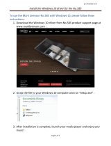
Task 1-4: Verify the Components and
Connectivity
Review the connectivity diagrams in Figure 1-1 and Figure 1-2 to gain a general
understanding of how to connect the DEFINITY AUDIX system. With DS
integration, Port B is available to connect a second terminal.
In these drawings, optional connection methods are shown in braces. The
optional connections are illustrated in diagrams presented later in the chapter.
For example, the options for terminal connections are listed in braces in Figure
1-1. These connections are explained in Task 2-3 on page 2-13. Refer to these
diagrams for details on the various connections.

Installation and Switch Administration for G3i/G3s/G3vs/R5vs/R5si/ProLogix
Switches, TN2181 Emulation, Display Set Integration
585-300-122
Issue 1
May 1999
Prerequisites
1-4Verify the Components and Connectivity
1
Compare the diagrams corresponding to your particular application with the
actual parts you received to make sure you have all the required parts. In
addition to the components illustrated in the diagrams, you can connect most
terminals, modems, and printers.
If you do not have all the required parts, follow your normal procedure with the
factory to acquire the missing parts. After you have reviewed the connectivity
diagram and have verified the DEFINITY AUDIX system components, proceed to
the tasks in Chapter 2, "
Hardware Installation".
NOTE:
If DEFINITY AUDIX will be used as a server for local area network (LAN)
applications such as I
NTUITY Message Manager, we recommend that you
install the LAN connecting block (see ‘‘
Alarm Connection Via an External
Modem’’ on page 2-10) before installing DEFINITY AUDIX.
Figure 1-1. DEFINITY AUDIX System Connectivity Diagram - DS Integration
DEFINITY
system
TN568
circuit
pack
DEFINITY AUDIX
adapter cable
Port B
Port C
Port A
Optional system access
terminal connections
Direct
Modem
ADUs
7400A data modules
cydxsl06 AWF 021799
Alarm via cross connect field
LAN
System access terminal
/