Page is loading ...

HCD1010A/W, HCD1010A/W, HCD1410A/W, HCD1410A/W 1
HCD1010R/N, HCD1410R/N, HMD1010R/N, HMD1410R/N
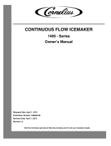
Horizon Elite™ Ice Machines (Remote Condensing)
801 Church Lane • Easton, PA 18040, USA
Toll free (877) 612-5086 • +1 (610) 252-7301
www.follettice.com
Following installation, please forward this manual
to the appropriate operations person.
Operation and Service Manual
Order parts online
www.follettice.com
01096122R00

2 HCD1010A/W, HCD1010A/W, HCD1410A/W, HCD1410A/W

HCD1010A/W, HCD1010A/W, HCD1410A/W, HCD1410A/W 3
Contents
Welcome to Follett. . . . . . . . . . . . . . . . . . . . . . . . . . . . . . . . . . . . . . . . . . . . . . . . . . . . . . . . . . . . . . . . . . . . . . . . . . . . . . 4
Before you begin ............................................................................... 4
Specications ................................................................................. 5
Electrical ................................................................................... 5
Evaporator unit .............................................................................. 5
Condensing unit ............................................................................. 5
Evaporator plumbing .......................................................................... 5
Ambient .................................................................................... 5
Refrigeration ................................................................................5
Weight ..................................................................................... 5
Ice production ............................................................................... 6
Dimensions and clearances ....................................................................7
Operation .....................................................................................9
Cleaning/sanitizing and preventive maintenance (all models) ..........................................9
Service ...................................................................................... 13
Ice machine operation (all models) ............................................................. 13
“Bin full” detection system ..................................................................... 15
Electrical system ............................................................................ 16
Mechanical System ............................................................................21
Evaporator disassembly ......................................................................21
Evaporator reassembly ....................................................................... 24
Refrigeration system ......................................................................... 29
Troubleshooting ..............................................................................32
Replacement parts ............................................................................ 34
Evaporator assembly ........................................................................ 34
Low-side assembly .......................................................................... 36
Electrical box ..............................................................................38
Integration kit – top-mount and RIDE remote ice delivery ...........................................40
Skins assembly .............................................................................42
1010 Single-phase condensing unit ............................................................. 44
1410 Single-phase condensing unit .............................................................45
1010 3-phase condensing unit ................................................................. 46
1410 3-phase condensing unit .................................................................47

4 HCD1010A/W, HCD1010A/W, HCD1410A/W, HCD1410A/W
Welcome to Follett
Follett equipment enjoys a well-deserved reputation for excellent performance, long-term reliability and outstanding
after-the-sale support. To ensure that this equipment delivers the same degree of service, we ask that you review
the installation manual (provided as a separate document) before beginning to install the unit. Our instructions are
designed to help you achieve a trouble-free installation. Should you have any questions or require technical help at
any time, please call our technical service group at (877) 612-5086 or +1 (610) 252-7301.
Before you begin
After uncrating and removing all packing material, inspect the equipment for concealed shipping damage. If
damage
is found, notify the shipper immediately and contact Follett Corporation so that we can help in the ling of a claim,
if necessary.
Check your paperwork to determine which model you have. Follett model numbers are designed to provide
information about the type and capacity of Follett equipment. Following is an explanation of the different model
numbers in the series.
ConfigurationApplication
S RIDE™
(RIDE remote
ice delivery
equipment)
T Top-mount
400 up to
454 lbs
(206kg)
1000/1010
up to
1036 lbs
(471kg)
1400/1410
up to
1450 lbs
(658kg)
1650 up to
1580 lbs
(717kg)
V Vision™
H Harmony™
B Ice storage bin
J Drop-in
M Ice Manager
diverter valve
system
CondenserSeriesVoltageIcemaker
C 208-230/60/1 (icemaking head)
Self-contained only.
D 115/60/1 (icemaking head)
Self-contained and remote. If remote
unit, high side is 208-230/60/1.
E 230/50/1 (icemaking head)
Self-contained only.
F 115/60/1 (icemaking head)
Remote only. High side is
208-230/60/3.
MC Maestro™
Chewblet
®
(400 Series)
HC Horizon
Chewblet
(1000, 1400,
1650 Series)
HM Horizon
Micro Chewblet
HC 1400C SVA
A Air-cooled, self-contained
W Water-cooled, self-contained
R Air-cooled, remote condensing unit
N Air-cooled, no condensing unit for
connection to parallel rack system
Chewblet
®
Ice Machine Model Number Configurations
CAUTION
• Warranty does not cover exterior or outside installations.
• Moving parts. Do not operate with front cover removed.
• Hot parts. Do not operate with cover removed.
• To reduce risk of shock, disconnect power before servicing.
• Drain line must not be vented.
• Water supply must have particle ltration.
• Most ice machine cleaners contain citric or phosphoric acid, which can cause skin irritation. Read caution label
on product and follow instructions carefully.
• Ice is slippery. Maintain counters and oors around dispenser in a clean and ice-free condition.
• Ice is food. Follow recommended cleaning instructions to maintain cleanliness of delivered ice.

HCD1010A/W, HCD1010A/W, HCD1410A/W, HCD1410A/W 5
Specications
Electrical
Separate circuit and equipment ground required.
Evaporator unit
Standard electrical: 115/60/1
Maximum fuse: 15A
Amperage: 5A
Condensing unit
1010 Single-Phase 1010 3-Phase 1410 Single-Phase 1410 3-Phase
Electrical 208-230V, 60Hz 208-230V, 60Hz 208-230V, 60Hz 208-230V, 60Hz
Max Circuit HVACR breaker size 15A 15A 30A 25A
Min Circuit Ampacity 10.7A 9.9A 19.3A 14.2A
Evaporator plumbing
§ 3/8" OD push-in water inlet (connection inside machine) - 3/8" OD tubing required
§ 3/4" MPT
§ 3/4" drain line must slope a minimum of 1/4" per foot (6 mm per 30.4 cm run).
§ Drain to be hard piped and insulated.
§ Water shut-off recommended within 10 feet (3 m).
§ Follett recommends installation of Follett water lter system (part# 00130286) in ice machine inlet water line.
Ambient
Evaporator unit
Air temperature 100 F/38 C max. 50 F/10 C min.
Water temperature 90 F/32 C max. 45 F/7 C min.
Water pressure 70 psi max. (483 kPa) 10 psi min. (69 kPa)
Condenser unit
Air temperature 120 F/49 C max. –20F/–29C min.
Refrigeration
§ 3/8" liquid line
§ 5/8" suction line
Note: Rack system installations require a capacity of 10,000 BTU/hr for 1010 machines and 13,000 BTU/hr for
1410 machinesat 0 F (–18 C) evaporator temperature. Evaporator pressure regulator (not supplied) is
required.
Weight
Evaporator unit: 125 lbs (57 kg)
Condensing unit: 225 lbs (102 kg)

6 HCD1010A/W, HCD1010A/W, HCD1410A/W, HCD1410A/W
Ice production
1010 ice machine capacity/24 hrs.
Ambient Air Temperature F/C
Potable Water Temperature F/C
F 60 70 80 90 100
C 16 21 27 32 38
50 1051 978 906 834 763 lbs
10 477 444 411 379 346 kg
60 994 925 855 796 737 lbs
16 451 420 388 361 335 kg
70 937 871 805 758 711 lbs
21 425 395 365 344 323 kg
80 904 839 774 727 680 lbs
27 410 381 351 330 309 kg
90 872 807 743 696 648 lbs
32 396 366 337 316 294 kg
1410 ice machine capacity/24 hrs.
Ambient Air Temperature F/C
Potable Water Temperature F/C
F 60 70 80 90 100
C 16 21 27 32 38
50 1474 1372 1269 1212 1154 lbs
10 669 623 576 550 524 kg
60 1385 1292 119 8 1148 1097 lbs
16 628 586 544 521 498 kg
70 1296 1212 112 7 1083 1039 lbs
21 588 550 511 492 472 kg
80 1239 115 5 1072 1030 988 lbs
27 562 524 487 468 449 kg
90 90 118 1 1099 1017 976 lbs
32 32 536 499 462 425 kg

HCD1010A/W, HCD1010A/W, HCD1410A/W, HCD1410A/W 7
Dimensions and clearances
§ Entire front of ice machine must be clear of obstructions/connections to allow removal.
§ 1" (26mm) clearance above ice machine for service.
§ 1" (26mm) minimum clearance on sides.
§ The intake and exhaust air grilles must provide at least 250 sq in (1615 sq cm) of open area.
§ Air-cooled ice machines – 18" (458 mm) minimum clearance between discharge and air intake-grilles.
A 21.26" (54.0 cm)
B 21.11" (53.6 cm)
C 23.77" (60.4 cm)
D 2.66" (6.8 cm)
E 19.59" (49.8 cm)
F 16.00" (40.6 cm)
G 2.73" (6.9 cm)
H 2.28" (15.3 cm)
I 6.04" (5.8 cm)
J 22.00" (55.9 cm)
K 22.69" (57.6 cm)
A
B
C (1410 ONLY)
D (1410 ONLY)
NEMA 5-15
RIGHT ANGLE
E
F
H
J
I
G
K
1410 ONLY
1410 ONLY

8 HCD1010A/W, HCD1010A/W, HCD1410A/W, HCD1410A/W
Condensing unit
36.25"
(921 mm)
25.5"
(648 mm)
26.08"
(662 mm)

HCD1010A/W, HCD1010A/W, HCD1410A/W, HCD1410A/W 9
Operation
Cleaning/sanitizing and preventive maintenance (all models)
Note: Do not use bleach to sanitize or clean the icemaker.
Preventive maintenance
Periodic cleaning of Follett’s icemaker system is required to ensure peak performance and delivery of clean,
sanitary ice. The recommended cleaning procedures that follow should be performed at least as frequently as
recommended, and more often if environmental conditions dictate.
Cleaning of the condenser can usually be performed by facility personnel. Cleaning of the icemaker system,
in most cases, should be performed by your facility’s maintenance staff or a Follett authorized service agent.
Regardless of who performs the cleaning, it is the operator’s responsibility to see that this cleaning is performed
according to the schedule below. Service problems resulting from lack of preventive maintenance will not be
covered under the Follett warranty.
Weekly exterior care
The exterior may be cleaned with a stainless cleaner such as 3M Stainless Steel Cleaner & Polish or equivalent.
Monthly condenser cleaning (air-cooled icemaker only)
1. Use a vacuum cleaner or stiff brush to carefully clean condenser coils of air-cooled icemakers to ensure
optimal performance.
2. When reinstalling counter panels in front of remote icemakers, be sure that ventilation louvers line up with
condenser air duct.
Semi-annual evaporator cleaning (every 6 months)
WARNING
• Wear rubber gloves and safety goggles (and/or face shield) when handling ice machine cleaner or sanitizer.
CAUTION
• Use only Follett approved SafeCLEAN Plus™ cleaning/sanitizing solution (part #01050863).
• DO NOT USE BLEACH.
• It is a violation of Federal law to use these solutions in a manner inconsistent with their labeling.
• Read and understand all labels printed on packaging before use.
Note: Complete procedure for cleaning an sanitizing MUST be followed. Ice must be collected for 10minutes
before putting ice machine back into service.
Fig. 1
1. Press the CLEAN button. The machine will drain. The
auger will run for a short time and then stop. Wait for
the LOW WATER light to come on.
LO WATER

10 HCD1010A/W, HCD1010A/W, HCD1410A/W, HCD1410A/W
Fig. 2
2. Mix 1 gal. (3.8L) 120 F (49 C) water and one 7oz.
(198g) packet of Follett SafeClean Plus (P/N
01050863).
3. Using a 1 quart (1L) container, slowly ll cleaning cup
until CLEANER FULL light comes on. Do not overll.
4. Place one Sani-Sponge™ in remaining sanitizing and
cleaning solution and retain for Step 9.
Note: Do not use bleach to sanitize or clean the icemaker.
CLEANER FULL
Fig. 3
5. Replace cover on cleaner cup. Machine will clean,
then ush 3 times in approximately 15 minutes. Wait
until machine restarts.
15
Fig. 4
6. To clean/sanitize ice transport tube – Press power
switch OFF

HCD1010A/W, HCD1010A/W, HCD1410A/W, HCD1410A/W 11
Fig. 5
7. Disconnect coupling as shown.
Fig. 6
8. Using disposable food service grade gloves, insert
dry Sani-Sponge.
9. Insert Sani-Sponge soaked in SafeClean Plus (from
Step 4).
10. Push both Sani-Sponges down ice transport tube
with supplied pusher tube.
1
2
3
16"
(407 mm)
Fig. 7
11. Remove and discard 16 inch (407 mm) pusher tube.

12 HCD1010A/W, HCD1010A/W, HCD1410A/W, HCD1410A/W
Fig. 8
12. Reconnect coupling. Press power switch ON. Ice
pushes Sani-Sponges through ice transport tube.
Fig. 9
13. Place a sanitary (2 gal. or larger) container in bin
or dispenser to collect Sani-Sponges and ice for 10
minutes.
14. Collect 5.5 lbs (3 kg) of ice from unit. Discard ice and
Sani-Sponges.

HCD1010A/W, HCD1010A/W, HCD1410A/W, HCD1410A/W 13
Service
Ice machine operation (all models)
Follett’s ice machine consists of ve distinct functional systems covered in detail as follows:
§ Water system
§ Electrical control system
§ Mechanical assembly
§ Refrigeration system
§ Bin full
The Horizon ice machine overview
The Follett Horizon ice machine uses a horizontal, cylindrical evaporator to freeze water on its inner surface. The
refrigeration cycle is continuous; there is no batch cycle. The evaporator is ooded with water and the level is
controlled by sensors in a reservoir. A rotating auger (17 RPM) continuously scrapes ice from the inner wall of the
evaporator. The auger moves harvested ice through the evaporator into an ice extrusion canal. The ice is forced
through a restrictive nozzle that squeezes out the water and creates the Chewblet. The continuous extrusion
process pushes the Chewblets through a transport tube into a dispenser or bin.
A solid state PC board controls and monitors the functionality of the ice machine. In addition to sequencing
electrical components, the board monitors various operational parameters. A full complement of indicator lights
allows visual status of the machine's operation. Additionally, the PC board controls the self-ushing feature of the
ice machine. The evaporator water is periodically drained and replenished to remove minerals and sediment.
A unique “bin full” detection system is incorporated in the Horizon ice machine. A switch located at the ice
discharge port of the machine detects the position of the transport tube. When the bin lls up with ice, the transport
tube moves out of the normal running position, and the switch turns the ice maker off. A domed housing at the end
of the transport tube contains the ice extrusion loads during shut down.
Harvest system diagram
Ice Transport Tube
Auger
Compression
Nozzle
Water Inlet

14 HCD1010A/W, HCD1010A/W, HCD1410A/W, HCD1410A/W
Water system
The water level in the evaporator is controlled by a feed solenoid and level detecting sensors. Referencing the
diagram below, water sensing probes extend down into the reservoir at the end of the evaporator assembly. The
system works via electrical conductivity as follows:
The probe labeled B is the common. When water is between any of the other probes and the common, the PC
board will sense the activation. During normal operation, the water level rises and falls between the Normal
High and Normal Low probes. As water is consumed to make ice, the level will fall until the Normal Low probe is
exposed, triggering the water feed solenoid on. Water will ll until the Normal High sensor is activated.
Note: The potable water total dissolved solids (TDS) content must be greater than 10 ppm for the water control
system to function properly. If using reverse osmosis water ltration system, ensure TDS level is greater than
10 ppm.
Water system diagram
Water level diagram
Common
Normal Hi
Normal Lo
Normal
Operating
Range

HCD1010A/W, HCD1010A/W, HCD1410A/W, HCD1410A/W 15
“Bin full” detection system
The Follett Horizon ice machine incorporates a unique “bin full” detection system that consists of the shuttle and
actuator. The shuttle incorporates a ag and switch. Referencing the gure below, the normal running position
of the ag is down, and the switch is closed. When the bin lls to the top and ice can no longer move through
the tube, the machine will force the shuttle ag up, opening the switch and shutting the machine off. The shuttle
actuator, located above the ice bin allows the ice to curl up within it when the bin is full. In this way, there are no
loads generated that would tend to lift off the lid of the bin.
Running Off
Running
Off
Shuttle ag and sensor
Shuttle actuator

16 HCD1010A/W, HCD1010A/W, HCD1410A/W, HCD1410A/W
Electrical system
ATTENTION!
To prevent circuit breaker/Hi-amp overload, wait 5 minutes before
restarting this unit. This allows the compressor to equalize and the
evaporator to thaw.
Normal control board operation
The PC board indicator lights provide all the information necessary to determine the machine's status. Green
indicator lights generally represent “go” or normal operation; Yellow indicators represent normal off conditions; Red
indicators generally represent alarm conditions, some of which will lock the machine off.
A ashing green light labeled POWER indicates power to the machine. All other normal operation status indicators
are covered as follows:
Ice machine disposition Operating conditions
FLASHINGON or OFF
Legend:
OFFON
1. Ice machine is making ice.
.
1. Normal running.
2. Ice machine is not making ice.
2. Normal time delay. When the bin lls with ice, the LOW BIN
light goes out momentarily and the refrigeration and auger
drive systems immediately shut down. (Note: The fan motor
will continue to run for 10 minutes to cool condenser) The TIME
DELAY light comes on, initiating the time delay period. When the
time delay expires, the machine will restart provided that the LOW
BIN light is on.
DIP Switch Settings

HCD1010A/W, HCD1010A/W, HCD1410A/W, HCD1410A/W 17
Error faults:
The Horizon PC board monitors various operating parameters including high pressure, auger gearmotor amperage
limits, clogged drain, and low water alarm conditions. There are three types of errors namely “soft” (time delay)
"hard" (reset), and “run”.
§ Soft errors will automatically reset after the 1 hour time delay or can be reset by cycling power.
§ Hard errors must be reset on the control board.
§ Run errors will give an indication of a problem, but will allow continuous normal operation.
Soft errors:
HI AMPS: The PC board monitors the amperage of the auger motor. Should the gear motor experience current
draw above the allowable limit, the machine will shut down and the TIME DELAY and HI AMP will be illuminated.
After the time delay the machine will restart and the TIME DELAY and HI AMP will clear.
LO WATER: During operation, the water level cycles between the normal low and normal high sensors. Should the
water be shut off to a running machine, a soft error will occur. The error sequence is as follows: During operation,
the water level falls to the normal low sensor, and when it does the water feed solenoid is energized. If water is not
detected at the normal low sensor within 10 seconds, a soft error will occur. The machine will shut down, but the
water feed solenoid will remain energized. Should water return, it will ll to the normal low sensor and the machine
will resume normal operation. The error will clear automatically.
HI PRESSURE: Should the refrigeration pressure rise above 425 psi, the machine will shut down and the TIME
DELAY and HIGH PRESSURE will be illuminated. After the time delay, and if the pressure has fallen back below
the reset point of 295 psi, the machine will restart and the TIME DELAY and HIGH PRESSURE will clear.
Hard error:
DRAIN CLOG: The drain clog sensor, located in the chassis will detect the presence of water just below the top
edge of the chassis. After the sensors are dired off, the machine must be reset on the control board to resume
operation.
Run errors:
DRAIN CLOG: When the machine shuts down on a full bin and there has been 30 minutes of cumulative
compressor run time, the machine will purge before starting. During this purge, if water does not get below the low
probe in the reservoir within 20 seconds, the Drain Clog LED will light. The machine will continue to run but this is
an indication of a poorly draining machine and must be addressed.
Relay output indication:
Each relay on the board has an indicator light associated with its output. For example, when the relay for the water
feed solenoid is energized, the adjacent indicator light glows green.
Evaporator ushing sequence:
During operation, the purge solenoid will open in order to drain water. There are two drain settings to choose from:
High TDS or Low TDS. (There is a rocker switch behind the front cover of the machine.) The intent is to drain the
Total Dissolved Solids from the machine while it makes ice.
While ice is being made, the TDS of the water in the evaporator increases in TDS concentration. Without periodic
draining, the TDS levels will climb to very detrimental levels, levels that will cause scale to form and cause poor
machine operation. The Low TDS setting will allow the machine to operate for one hour before going through the
ushing sequence; the High TDS setting will allow the machine to run for 10 minutes before going through the
ushing sequence.
The ushing sequence toggles the purge and ll solenoids three times. That is, the purge solenoid will energize
until the water level drops below the low probe. The ll solenoid then energizes until water reaches the high probe,
and so on for 3 cycles.
Typically, High TDS might be considered levels above 200 PPM, but local experience and varying water chemistry
may compel a High TDS setting for best performance in even lower TDS levels.
Off cycle: At the completion of off-cycle time delay, the machine checks for a cumulative 30 minutes of ice making
time since the last off-cycle ush. If the cumulative ice making time exceeds 30 minutes, the machine will open
the drain valve for 60 seconds to drain the evaporator in its entirety. It will then rell with water and begin making
ice. If the ice making time is less than 30 minutes, the machine will start and begin making ice without draining the
evaporator.

18 HCD1010A/W, HCD1010A/W, HCD1410A/W, HCD1410A/W
Wiring diagram, evaporator unit
Gearmotor data
Gearmotor current 2.8A @ 115 V
Gearmotor torque-out (high amp) trip point: 5.6A
Resistance of windings
115 vac gearmotor (Bison):
White to Black: 3Ω
White to Red: –3Ω
Red to Black: 6Ω

HCD1010A/W, HCD1010A/W, HCD1410A/W, HCD1410A/W 19
Single-phase condensing unit wiring diagram
T1
BLACK
COMPRESSOR
CONTACTOR
T1
L1
T2
L2
RECEIVER
HEATER
L3
L2
T3
T2
COMPRESSOR
CONTACTOR COIL
see note A
TERMINAL
BOARD
P1
HP LP
T3
L3
START
CAPACITOR
WITH BLEEDER
RESISTOR
4
6
1
L2
L3 T3
T1
F1 F2
FC
FAN 1
POTENTIAL RELAY
see note B
5
2
FAN 2
L1
CRANK CASE
HEATER
COMPRESSOR
TERMINAL
C
GRD
L1
S
R
RED
YELLOW
RED
BLACK
YELLOW
RUN
CAPACITOR
HEATER
THERMOSTAT
POWER SUPPLY
230-60-1
COMPRESSOR CONTACTOR
NC AUXILIARY SWITCH

20 HCD1010A/W, HCD1010A/W, HCD1410A/W, HCD1410A/W
3-phase condensing unit wiring diagram
FAN 2
L1
COMPRESSOR
TERMINAL
C
S
R
L1 T1
RED
YELLOW
BLACK
ICM402
3 PHASE
MONITOR
T1
L1
T2
L2
L3
L2
T3
T2
COMPRESSOR
CONTACTOR
COIL
see note A
TERMINAL
BOARD
P1
HP LP
T3
L3
L2 L3 T3T1 F1 F2
FFC
FAN 1
Y-
OUT
C
115
VAC
CRANK CASE
HEATER
230
VAC
L1
D.T.
L2 L3
TO "230 VAC"
AT PHASE
MONITOR
TERMINAL
BOARD
A
B
RECEIVER
HEATER
TO "L1"
AT TERMINAL
BOARD
TO "Y-OUT"
AT PHASE
MONITOR
A
C
TO "C"
AT PHASE
MONITOR
TO "P1"
AT TERMINAL
BOARD
HEATER
THERMOSTAT
COMPRESSOR
CONTACTOR NC
AUXILIARY SWITCH
B
C
GRD
TO "L2"
AT TERMI
NAL
BOARD
POWER SUPPLY
230-60-3
Y
/