Robe Robin iParfect 150 FW User manual
- Category
- Stroboscopes & disco lights
- Type
- User manual
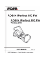
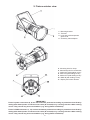
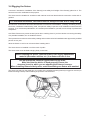
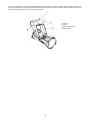
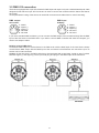
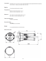
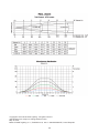
Robe Robin iParfect 150 FW: a powerful outdoor wash light fixture with a 150W COB LED engine, designed for professional applications. It offers smooth color mixing, motorized zoom, and an impressive output with a maximum illuminance of 6,800 lux at 5 meters. The iParfect 150 FW is IP65 rated for outdoor use and features various control options, including DMX, RDM, and wireless DMX.
Robe Robin iParfect 150 FW: a powerful outdoor wash light fixture with a 150W COB LED engine, designed for professional applications. It offers smooth color mixing, motorized zoom, and an impressive output with a maximum illuminance of 6,800 lux at 5 meters. The iParfect 150 FW is IP65 rated for outdoor use and features various control options, including DMX, RDM, and wireless DMX.


-
 1
1
-
 2
2
-
 3
3
-
 4
4
-
 5
5
-
 6
6
-
 7
7
-
 8
8
-
 9
9
-
 10
10
-
 11
11
-
 12
12
-
 13
13
-
 14
14
-
 15
15
-
 16
16
-
 17
17
-
 18
18
-
 19
19
-
 20
20
-
 21
21
-
 22
22
-
 23
23
-
 24
24
-
 25
25
-
 26
26
-
 27
27
-
 28
28
-
 29
29
-
 30
30
-
 31
31
-
 32
32


Robe Robin iParfect 150 FW User manual
- Category
- Stroboscopes & disco lights
- Type
- User manual
Robe Robin iParfect 150 FW: a powerful outdoor wash light fixture with a 150W COB LED engine, designed for professional applications. It offers smooth color mixing, motorized zoom, and an impressive output with a maximum illuminance of 6,800 lux at 5 meters. The iParfect 150 FW is IP65 rated for outdoor use and features various control options, including DMX, RDM, and wireless DMX.
Ask a question and I''ll find the answer in the document
Finding information in a document is now easier with AI
Related papers
-
Robe Robin iParfect 150 FW TW User manual
-
-
-
-
-
-
-
-
-
Other documents
-
Access Lighting 20786LED Installation guide
-
Gamma Double Mist Panel 88×20 IP Owner's manual
-
Anolis ArcPar™ 150 Outdoor User manual
-
-
-
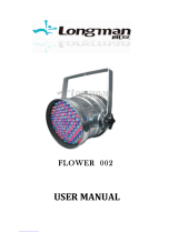 Longman Fliwer 002 User manual
-
-
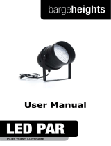 Bargeheights LED PAR User manual
-
IMG STAGELINE 38.8080 User manual
-
ETC SmartModule 2 Connection And Setup Manual

