Extron IN1608 User manual

Category
Video switches
Type
User manual

This manual is also suitable for

1
IMPORTANT:
Refer to www.extron.com for the complete
user guide, installation instructions, and
specifications before connecting the
product to the power source.
IMPORTANT:
Refer to www.extron.com for the complete
user guide, installation instructions, and
specifications before connecting the
product to the power source.
IN1608 Series • Setup Guide
The Extron IN1608 Scaling Presentation Switcher is an eight input, HDCP-compliant video scaler that accepts a wide variety of audio and video
formats. This guide allows an experienced user to set up and congure IN1608, IN1608 SA, IN1608 MA, IN1608 IPCP SA, and IN1608 IPCP MA 70
scalers. It covers how to perform basic operations using the front panel controls and selected Simple Instruction Set (SIS) commands.
NOTE: For full installation, configuration, menus, connector wiring, and operation details, see the IN1606 and IN1608 Series User Guide, at
www.extron.com. For installation, configuration, and operation details of the IPCP Pro 350 control processor, see the IPCP Pro Series
User Guide.
Installation
IN1608 Series Rear Panel Connectors
100-240V ~ 1.5 A MAX
1
CONFIGURABLE
HDMI HDMI
5
8
C
RS-232 IR
RS-232 IR
Tx Rx Tx RxG
Tx Rx Tx RxG
Tx Rx Tx RxG
HDMI
A
B
3
INPUTS OUTPUTS AUDIO INPUTS OUTPUTS REMOTE
2
6
7
4
Tx Rx
RS-232
G
LAN 1
LAN 2 LAN 3
2x25W(8Ω)/2x50W(4Ω)
RESET
L1R
L
R
L2
R
L
3
R
CLASS 2 WIRING
L4
R
L5R
+48V
+48V
12
LR
VARIABLE
1
2
MIC/LINE
L6
R
50/60 Hz
RS-232 IR
IN1608 IPCP SA
OVER DTP
OVER DTP
AMPLIFIED OUTPUT
G
Tx Rx
G
Tx Rx
G
Tx Rx
34G
12RTSCTS
COM 1 COM 2 COM 3DIGITAL I/O
1
SG
SG
2
IR/SERIAL RELAYS
1 2 C 3 4 C
PWR OUT = 6W
eBUS
+V+S -S G
R
SIG
DTP IN
LINK SIG
DTP IN
LINK SIG
DTP OUT
LINK
JL
AB CDGH EFIK
Power and Input Connections Output Connections Control Connections
A
AC power connector
B
Configurable analog 15-pin HD (VGA) connectors (inputs 1 and 2)
C
HDMI input connectors (inputs 3 through 6)
D
DTP input and corresponding RS-232/IR Over DTP connectors
(inputs 7 and 8)
E
Analog audio input connectors (associated with inputs 1 through 6)
F
Mic/Line audio input connectors and adjacent phantom power LEDs
G
DTP output connector and
corresponding RS-232/IR Over
DTP connector (output C)
H
HDMI output connectors
(outputs A and B)
I
Analog audio output connectors
J
Amplified audio output connector
(SA, MA, and IPCP models only)
K
Remote RS-232
connector
L
IPCP Pro 350 control
processor (IPCP
models only)
M
LAN connector
(IN1608, SA, and MA
models only)
Figure 1. IN1608 Series Rear Panel Connectors (IN1608 IPCP SA Shown)
The IN1608 IPCP models feature a built-in Extron IPCP Pro 350 control processor for controlling and monitoring a variety
of external devices, such as projectors and lights. See the IPCP Pro Series Setup Guide for more details.
NOTE: The non-IPCP models have a LAN connector next to the Remote RS-232 connector (see
M
to the
right) instead of the IPCP Pro 350 control processor.
Mounting and Cabling
Step 1 Mount the device
a. Turn off or disconnect all equipment
power sources.
b. Mount IN1608 scalers to a rack
using the pre-installed rack ears
or use an optional mounting kit
for under-the-desk mounting (see
the two images to the right). The
IN1608 comes in a 1U, full rack width
enclosure. All other IN1608 models
come in 2U, full rack width enclosures.
Tx Rx
RS-232
G
LAN
2x25W(8Ω)/2x50W(4Ω)
RESET
OUTPUTS
REMOTE
LR
CLASS 2 WIRING
12
LR
VARIABLE
AMPLIFIED OUTPUT
O
M
IN1608 SA
Rack Ears
Rack Mounting
#8 Screw
(4) Places
Each Side
MBU 149
Mounting Bracket
Mounting Screws
(2) Places
Each Side
Furniture Mounting
2
IN1608 Series • Setup Guide (Continued)
Step 2 Connect inputs
a. Connect analog video sources to the VGA connectors (see gure 1,
B
on page 1).
b. Connect digital HDMI or DVI (with an appropriate adapter) sources to the HDMI connectors (see gure 1,
C
).
c. Connect a DTP transmitter to the DTP input connectors (see gure 1,
D
). For cable wiring and recommendations, see Twisted Pair
Recommendations for DTP Communication below.
Signal LED Lights green when the unit is receiving an active video signal from a DTP transmitter.
Link LED Lights amber when a valid link is established to a DTP transmitter.
d. To pass serial, infrared data, or other control signals (for serial control of a source), connect the control device to the RS-232 and IR Over
DTP captive screw connectors (see RS-232 and IR Over DTP Wiring on page 3).
e. Connect analog audio input sources to the 5-pole captive screw connectors (see gure 1,
E
). See Audio Wiring on page 3.
f. Connect Mic/Line audio input sources to the 3-pole captive screw connectors (see gure 1,
F
).
Step 3 Connect outputs
a. Connect a DTP receiver to the DTP output connector (see gure 1,
G
). For cable wiring and recommendations, see Twisted Pair
Recommendations for DTP Communication below.
Signal LED Lights green when the IN1608 is outputting active video to a DTP receiver.
Link LED Lights amber when a valid link is established between the IN1608 and a DTP receiver.
b. To pass serial, infrared data, or other control signals to a DTP device, connect a control device to the RS-232 and IR Over DTP captive
screw connector (see RS-232 and IR Over DTP Wiring on page 3).
c. Connect suitable video displays to the HDMI connectors (see gure 1,
H
).
d. Connect analog audio output devices to the 3.5 mm, 5-pole captive screw connectors (see gure 1,
I
). See Audio Wiring on page 3.
e. For SA, MA, and IPCP models, connect an audio output device to the 5 mm, 4-pole or 2-pole captive screw connector (see gure 1,
J
).
Step 4 Connect control devices
a. To control non-IPCP models through Ethernet, connect a LAN or WAN to the LAN connector (see
M
on page 1). For the IPCP models,
connect a LAN or WAN to any of the LAN connectors on the IPCP Pro control processor (see gure 1,
L
). The default IP address is
192.168.254.254. The default subnet mask is 255.255.0.0.
b. For serial RS-232 control, connect a host device to the 3-pole captive screw connector (see gure 1,
K
). The default baud rate is 9600.
c. For control through USB, connect a host device to the front panel USB mini-B port (see gure 2,
A
).
Step 5 Set up the IPCP Pro control processor (IN1608 IPCP models only)
See the IPCP Pro Series Setup Guide for installation details.
Step 6 Connect power
Connect a 100 to 240 VAC, 50-60 Hz power source to the AC power connector (see gure 1,
A
).
Twisted Pair Recommendations for DTP Communication
Extron recommends using the following practices to achieve full transmission distances and reduce
transmission errors:
Use Extron XTP DTP 24 SF/UTP cable for the best performance. At a minimum, Extron recommends
24 AWG, solid conductor, STP cable with a minimum bandwidth of 400 MHz.
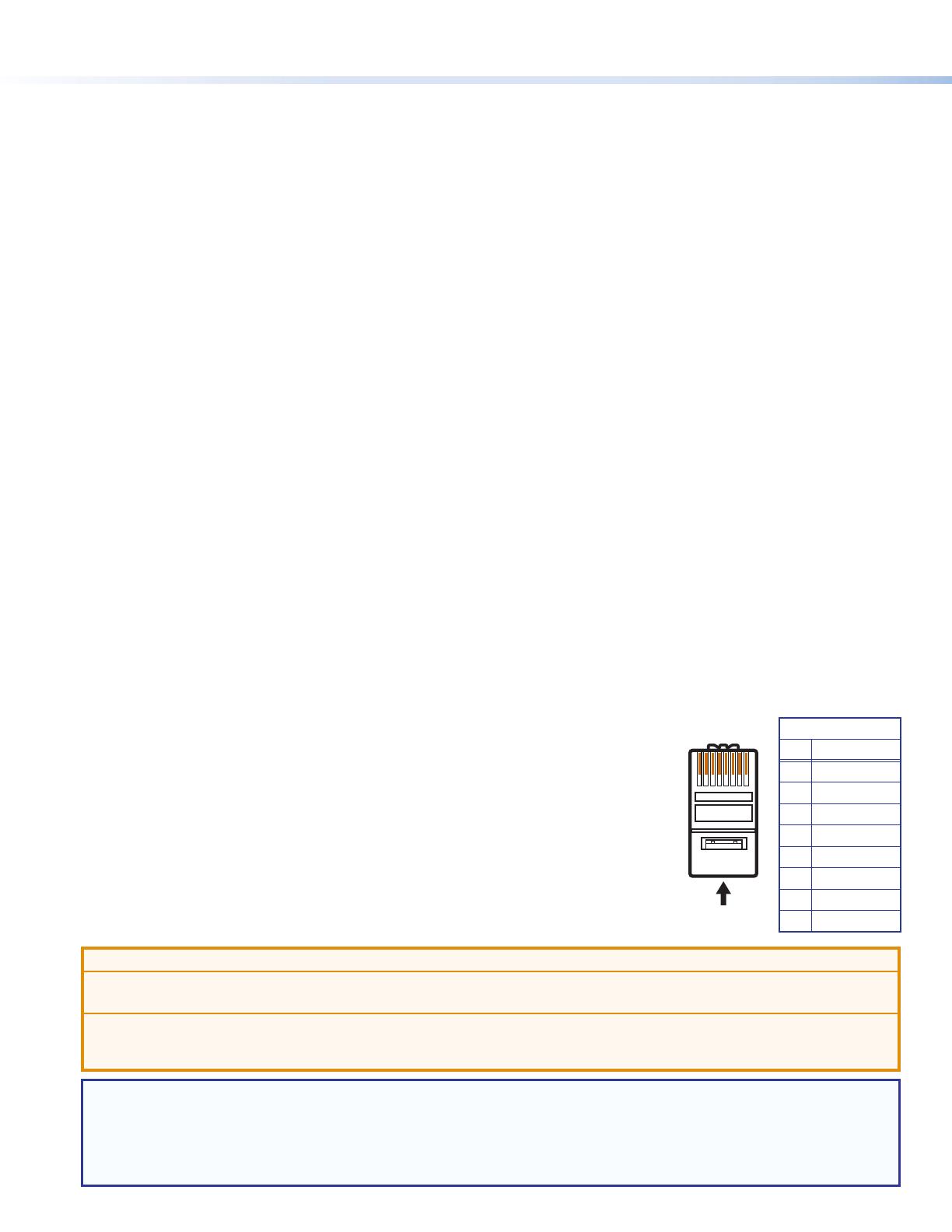
Terminate cables with shielded connectors to the TIA/EIA-T568B standard (shown to the right).
Limit the use of more than two pass-through points, which may include patch points, punch down
connectors, couplers, and power injectors. If these pass-through points are required, use shielded
couplers and punch down connectors.
ATTENTION:
Do not connect these connectors to a computer or telecommunications network.
Ne connectez pas ces ports à des données informatiques ou à un réseau de télécommunications.
DTP remote power is intended for indoor use only. No part of the network that uses DTP remote power should be routed outdoors.
L’alimentation DTP à distance est destiné à une utilisation en intérieur seulement. Aucune partie du réseau qui utilise l’alimentation DTP
à distance ne peut être routée en extérieur.
NOTE: When using shielded twisted pair cable in bundles or conduits, consider the following:
Do not exceed 40% ll capacity in conduits.
Do not comb the cable for the rst 20 meters, where cables are straightened, aligned, and secured in tight bundles.
Loosely place cables and limit the use of tie wraps or hook-and-loop fasteners.
Separate twisted pair cables from AC power cables.
TIA/EIA-T568B
Pin Wire Color
1 White-orange
2 Orange
3 White-green
4 Blue
5 White-blue
6 Green
7 White-brown
8 Brown
12345678
RJ-45
Connector
Insert Twisted
Pair Wires
Pins:
Pin
1
2
3
4
5
6
7
8
Wire color
White-green
Green
White-orange
Blue
White-blue
Orange
White-brown
Brown
Wire color
T568A T568B
White-orange
Orange
White-green
Blue
White-blue
Green
White-brown
Brown
3
Balanced Audio Output
Tip
Ring
Tip
Ring
Slee
ves
Unbalanced Audio Output
Tip
No Ground Here
No Ground Here
Tip
Sleeves
LR
LR
Unbalanced Audio InputBalanced Audio Input
Tip
Ring
Tip
Ring
Slee
ves
Tip
Sleeve
Sleeve
Tip
LR
LR
Do not tin the wires!
RS-232 and IR Over DTP Wiring
To pass bidirectional serial command signals between DTP-compatible devices, connect a control device to the three leftmost poles (Tx, Rx, and
G) of the 5-pole captive screw connector. To transmit and receive IR signals, connect a control device to the three rightmost poles (G, Tx, and Rx).
NOTE: RS-232 and IR data can be transmitted or received simultaneously.
Audio Wiring
Wire the audio input and output connectors as shown below and to the right. Use the supplied tie wrap to strap the audio cable to the extended
tail of the connector. This does not apply to the amplied audio output connectors on the IN1608 SA, IN1608 MA, or IN1608 IPCP models.
ATTENTION: For unbalanced outputs, do not connect
wires to the “-” poles (see the Extron Audio Wiring Card).
ATTENTION : Pour les sorties asymétriques, ne connectez
pas de câbles aux pôles «-» (voir le Audio Wiring Card
d’Extron).
NOTE: The length of exposed wires is critical. The ideal
length is 3/16 inch (5 mm).
Front Panel Overview
eBUS
OVER
LIMIT
S
Tx
Rx
RTS
12
1
3
1
4
2
3
1
4
2
CTS
23
COM
IR/S
I/O RELAYS
VOLUME
SCALING PRESENTATION SWITCHER
IN1608
INPUTS
1
HDCP
SIGNAL
OUTPUTS
ENTER
MENU
Extron
2 3 4 5 6 7 8 A B C
INPUTS
1 2 3 4 5 6 7 8
CONFIG
AB CDEF
G
Figure 2. Front Panel Features (IN1608 IPCP SA Shown)
A
Front panel configuration port Connect a host device to the USB mini-B port for device conguration, control, and rmware upgrades.
B
Input selection buttons (1-8) Press one of these buttons to select an input. The buttons light amber for audio and video, green for video
only, or red for audio only.
C
Status LED indicators
Input signal LEDs Light green for each input when active video content is detected.
Output signal LEDs Remain lit green when active video is being output or blink amber when output video and sync are disabled.
Input HDCP LEDs Light green for each input signal that is HDCP-encrypted. Analog inputs 1 and 2 cannot be HDCP-encrypted.
Output HDCP LEDs Light green for an output when it is currently HDCP-encrypted.
D
Menu and Enter buttons Press these buttons to access and navigate the on-screen display menu system.
E
Navigation buttons Press these buttons to navigate through the on-screen display menu system or change selected settings.
F
Volume knob and LED indicators Rotate the Volume knob to adjust the program volume
(default). The eight Volume LED indicators light according to the volume level. The LEDs light in
order from bottom to top to indicate steps from 1% (-99 dB) to 99% (-1 dB). The bottom LED
blinks when the volume is muted. The top LED blinks when the volume is 100% (0 dB).
G
IPCP Pro 350 LED indicators See the IPCP Pro Series Setup Guide for details.
Configuring IN1608 Scalers
IN1608 scalers can be congured through front panel controls and the on-screen display (OSD)
menu, the internal Web pages, the Extron Product Conguration Software, or SIS commands.
On-screen Display (OSD) Menu System
To congure IN1608 scalers using the OSD menu, connect a display to either HDMI output or to a
DTP receiver through the DTP output connector. The OSD menu consists of nine submenus that can
be accessed using the front panel Menu or Enter button (see the example to the right).
NOTE: Press and hold the Enter button for 10 seconds to edit settings in the
Communication submenu.
4
68-1916-51 Rev. A
05 14
Extron USA Headquarters
+1.800.633.9876 (Inside USA/Canada Only)
Extron USA - West: +1.714.491.1500 FAX: +1.714.491.1517
Extron USA - East: +1.919.850.1000 FAX: +1.919.850.1001
© 2014 Extron Electronics — All rights reserved. All trademarks mentioned are the property of their respective owners. www.extron.com
Internal Web Pages
To congure IN1608 scalers using the factory-installed Web pages in a
Web browser, connect the Ethernet port on the device to a LAN or WAN
(see the example to the right). The default IP address is 192.168.254.254.
The default subnet mask is 255.255.0.0.
Extron Product Configuration Software
To congure IN1608 scalers using the Extron Product Conguration
Software (PCS), install the software (available on the Extron website,
www.extron.com) to a PC connected to the scaler via Ethernet or front
panel USB Cong port. After the installation, start the program. For full
instructions, press <F1> on the keyboard or click the ? button in the
software and select Help File.
Firmware Upgrades
The rmware of the scaler can be upgraded via the internal Web pages or the Extron Firmware Loader program (available at www.extron.com).
Basic SIS Command Table
IN1608 scalers can be congured with specic SIS commands via an RS-232, USB, or Ethernet connection. Use the Extron DataViewer utility
or a control system to send and receive SIS commands. The table below lists a selection of SIS commands. For a full list of SIS commands and
variables, see the IN1606 and IN1608 Series User Guide at www.extron.com.
Command ASCII Command
(Host to Device)
Response
(Device to Host)
Additional Description
Select audio and video input
X!! InX!
All] Selects audio and video input X!.
Select video input only
X!& InX!
RGB] Selects the video only input X!.
Select audio input only
X!$ InX!
Aud] Selects the audio only input X!.
Execute Auto-Image
A
Img0
]
Executes an Auto-Image on the current input.
Execute Auto-Image and ll
1*A
Img1
]
Executes an Auto-Image and lls the output.
Execute Auto-Image and follow
2*A
Img2
]
Executes an Auto-Image and maintains the aspect ratio of
the current input.
Mute video to black
1B
Vmt1
]
Mutes the video and displays a black output.
Mute video and sync
2B
Vmt2
]
Mutes the video and sync output.
Unmute video and sync
0B
Vmt0
]
Unmutes the video.
NOTE: By default, setting the audio mute with the following commands affects all outputs (configurable through group masters).
Set master audio mute
ED7*X(GRPM} GrpmD07*X(]
Enable or disable master audio mute.
View master audio mute status
ED7GRPM} X(]
View the current master audio mute status.
Enable executive mode 1
1X
Exe1
]
Locks the entire front panel.
Enable executive mode 2
2X
Exe2
]
Locks the front panel except for input selection and volume
control.
Disable executive modes
0X
Exe0
]
Allows all front panel adjustments and selections.
Set scaler IP address
EX4)CI} Ipi
X4)]
Species a new scaler IP address.
Set scaler DHCP mode
EX(DH} IdhX(]
Enables or disables DHCP (0 = default).
Set subnet mask
EX4!CS} Ips
X4!]
Species a new subnet mask.
Set gateway IP address
EX4@CG} Ipg
X4@]
Species a new gateway IP address.
Reboot networking
E2BOOT} Boot2]
Restarts the network connection after IP or DHCP changes.
NOTE: IP settings will not take effect until the E2BOOT} command is executed.
NOTES:
X! = Input selection (1-8)
X( = Enable or disable (0 = off or disabled; 1 = on or enabled)
X4) = IP address (xxx.xxx.xxx.xxx; 192.168.254.254 = default)
X4! = Subnet mask (xxx.xxx.xxx.xxx; 255.255.0.0 = default)
X4@ = Gateway address (xxx.xxx.xxx.xxx; 0.0.0.0 = default)
  • Page 1 1
  • Page 2 2
  • Page 3 3
  • Page 4 4

Extron IN1608 User manual

Category
Video switches
Type
User manual
This manual is also suitable for

Ask a question and I''ll find the answer in the document

Finding information in a document is now easier with AI

in other languages