Page is loading ...

TPA 250 Series
™
High Density Connectorized DC Distribution Fuse Panel
Technical Manual
Effective: March 2021

2
C048-784-30 R01, Rev. B (03/2021)
The following sections contain important safety information that must be followed during the installation and operation of
the equipment. Read all of the instructions before installing or operating the equipment, and save this manual for future
reference.
There may be multiple warnings associated with the call out. Example:
ATTENTION provides specic regulatory/code requirements that may aect the placement of equipment and /or
installation procedures.
ATTENTION:
NOTICE provides additional information to help complete a specic task or procedure.
NOTICE:
ELECTRICAL HAZARD WARNING provides electrical safety information to PREVENT INJURY OR DEATH
to the technician or user.
WARNING! ELECTRICAL HAZARD
FUMES HAZARD WARNING provides fumes safety information to PREVENT INJURY OR DEATH to the
technician or user.
WARNING! FUMES HAZARD
FIRE HAZARD WARNING provides ammability safety information to PREVENT INJURY OR DEATH to the
technician or user.
WARNING! FIRE HAZARD
This WARNING provides safety information for both Electrical AND Fire Hazards
WARNING! ELECTRICAL & FIRE HAZARD
CAUTION provides safety information intended to PREVENT DAMAGE to material or equipment.
CAUTION!
GENERAL HAZARD WARNING provides safety information to PREVENT INJURY OR DEATH to the
technician or user.
WARNING! GENERAL HAZARD
Safety Notes
Alpha Technologies Services, Inc. considers customer safety and satisfaction its most important priority. To reduce the
risk of injury or death and to ensure continual safe operation of this product, certain information is presented dierently in
this manual. Alpha
®
tries to adhere to ANSI Z535 and encourages special attention and care to information presented in
the following manner:

3
C048-784-30 R01, Rev. B (03/2021)
TPA 250 Series
™
High Density Connectorized DC Distribution Fuse Panel
Technical Manual
C048-784-30 R01, Rev. B
Eective: March 2021
©
2021 by Alpha Technologies Services, Inc.
Disclaimer
Images contained in this manual are for illustrative purposes only. These images may not match your installation.
Operator is cautioned to review the drawings and illustrations contained in this manual before proceeding. If there are
questions regarding the safe operation of this powering system, please contact Alpha Technologies Services, Inc. or your
nearest Alpha representative.
Alpha
®
shall not be held liable for any damage or injury involving its enclosures, power supplies, generators, batteries or
other hardware if used or operated in any manner or subject to any condition not consistent with its intended purpose or is
installed or operated in an unapproved manner or improperly maintained.
Contact Information
Sales information and customer service in USA
(7AM to 5PM, Pacic Time): 1 800 322 5742
Complete Technical Support in USA
(7AM to 5PM, Pacic Time or 24/7 emergency support): 1 800 863 3364
Sales information and Technical Support in Canada: 1 888 462 7487
Website: www.alpha.com

4
C048-784-30 R01, Rev. B (03/2021)
Contents
1.0 Purpose and Applicability � � � � � � � � � � � � � � � � � � � � � � � � � � � � � � � � � � � � � � � � � � � � � � � � � 5
1�1 Product Model � � � � � � � � � � � � � � � � � � � � � � � � � � � � � � � � � � � � � � � � � � � � � � � � � � � � � � � � � � � � � � � � � � � � 5
2.0 Theory of Operation � � � � � � � � � � � � � � � � � � � � � � � � � � � � � � � � � � � � � � � � � � � � � � � � � � � � � � � 5
2�1 Introduction � � � � � � � � � � � � � � � � � � � � � � � � � � � � � � � � � � � � � � � � � � � � � � � � � � � � � � � � � � � � � � � � � � � � � � � 5
2�2 Features � � � � � � � � � � � � � � � � � � � � � � � � � � � � � � � � � � � � � � � � � � � � � � � � � � � � � � � � � � � � � � � � � � � � � � � � � 5
3.0 Unpacking and Inspection � � � � � � � � � � � � � � � � � � � � � � � � � � � � � � � � � � � � � � � � � � � � � � � � � 6
3�1 Package Contents � � � � � � � � � � � � � � � � � � � � � � � � � � � � � � � � � � � � � � � � � � � � � � � � � � � � � � � � � � � � � � � � � 6
4.0 Installation � � � � � � � � � � � � � � � � � � � � � � � � � � � � � � � � � � � � � � � � � � � � � � � � � � � � � � � � � � � � � � � � 6
4�1 Installation Preparation � � � � � � � � � � � � � � � � � � � � � � � � � � � � � � � � � � � � � � � � � � � � � � � � � � � � � � � � � � � � � � 6
4�1�1 Elevated Operating Ambient Temperature � � � � � � � � � � � � � � � � � � � � � � � � � � � � � � � � � � � � � � � � � � � 6
4�1�2 Reduced Air Flow � � � � � � � � � � � � � � � � � � � � � � � � � � � � � � � � � � � � � � � � � � � � � � � � � � � � � � � � � � � � � � 6
4�1�3 Mechanical Loading � � � � � � � � � � � � � � � � � � � � � � � � � � � � � � � � � � � � � � � � � � � � � � � � � � � � � � � � � � � � 6
4�1�4 Circuit Overloading � � � � � � � � � � � � � � � � � � � � � � � � � � � � � � � � � � � � � � � � � � � � � � � � � � � � � � � � � � � � 6
4�1�5 Reliable Earthing � � � � � � � � � � � � � � � � � � � � � � � � � � � � � � � � � � � � � � � � � � � � � � � � � � � � � � � � � � � � � � 6
4�1�6 Disconnect Device � � � � � � � � � � � � � � � � � � � � � � � � � � � � � � � � � � � � � � � � � � � � � � � � � � � � � � � � � � � � � 6
4�2 Mounting � � � � � � � � � � � � � � � � � � � � � � � � � � � � � � � � � � � � � � � � � � � � � � � � � � � � � � � � � � � � � � � � � � � � � � � � � 7
4�2�1 Optional Cable Lacing Bar Kit (C750-283-10) � � � � � � � � � � � � � � � � � � � � � � � � � � � � � � � � � � � � � � � � 7
4�2�2 Optional Rear Rack Support Kit (C750-277-10) � � � � � � � � � � � � � � � � � � � � � � � � � � � � � � � � � � � � � � 8
4�3 Chassis Ground � � � � � � � � � � � � � � � � � � � � � � � � � � � � � � � � � � � � � � � � � � � � � � � � � � � � � � � � � � � � � � � � � � � 8
4�4 Input Connections � � � � � � � � � � � � � � � � � � � � � � � � � � � � � � � � � � � � � � � � � � � � � � � � � � � � � � � � � � � � � � � � � � 9
4�4�1 Safety Covers � � � � � � � � � � � � � � � � � � � � � � � � � � � � � � � � � � � � � � � � � � � � � � � � � � � � � � � � � � � � � � � � 9
4�5 Output Connections � � � � � � � � � � � � � � � � � � � � � � � � � � � � � � � � � � � � � � � � � � � � � � � � � � � � � � � � � � � � � � � 10
4�6 Fuse Installation � � � � � � � � � � � � � � � � � � � � � � � � � � � � � � � � � � � � � � � � � � � � � � � � � � � � � � � � � � � � � � � � � � 10
4�7 Alarm Connections � � � � � � � � � � � � � � � � � � � � � � � � � � � � � � � � � � � � � � � � � � � � � � � � � � � � � � � � � � � � � � � � 10
5.0 Operation � � � � � � � � � � � � � � � � � � � � � � � � � � � � � � � � � � � � � � � � � � � � � � � � � � � � � � � � � � � � � � � � � 11
5�1 LED Display � � � � � � � � � � � � � � � � � � � � � � � � � � � � � � � � � � � � � � � � � � � � � � � � � � � � � � � � � � � � � � � � � � � � � 11
5�1�1 A Power LED � � � � � � � � � � � � � � � � � � � � � � � � � � � � � � � � � � � � � � � � � � � � � � � � � � � � � � � � � � � � � � � � 11
5�1�2 B Power LED � � � � � � � � � � � � � � � � � � � � � � � � � � � � � � � � � � � � � � � � � � � � � � � � � � � � � � � � � � � � � � � � 11
5�1�3 Alarm LED � � � � � � � � � � � � � � � � � � � � � � � � � � � � � � � � � � � � � � � � � � � � � � � � � � � � � � � � � � � � � � � � � � 11
6.0 Product Specications � � � � � � � � � � � � � � � � � � � � � � � � � � � � � � � � � � � � � � � � � � � � � � � � � � � �12
7.0 Models and Accessories � � � � � � � � � � � � � � � � � � � � � � � � � � � � � � � � � � � � � � � � � � � � � � � � � �13
Appendix A: Mechanical Drawings . . . . . . . . . . . . . . . . . . . . . . . . . . . . . . . . . . . . . 16
A�1 Front/Rear Detail � � � � � � � � � � � � � � � � � � � � � � � � � � � � � � � � � � � � � � � � � � � � � � � � � � � � � � � � � � � � � � � � � 16
A�2 Left/Right Detail � � � � � � � � � � � � � � � � � � � � � � � � � � � � � � � � � � � � � � � � � � � � � � � � � � � � � � � � � � � � � � � � � � 17
A�3 Top Detail � � � � � � � � � � � � � � � � � � � � � � � � � � � � � � � � � � � � � � � � � � � � � � � � � � � � � � � � � � � � � � � � � � � � � � � 18
A�4 Rear Support Kit - Minimum Depth (C750-277-10) � � � � � � � � � � � � � � � � � � � � � � � � � � � � � � � � � � � � � � � 19
A�5 Rear Support Kit - Maximum Depth (C750-277-10) � � � � � � � � � � � � � � � � � � � � � � � � � � � � � � � � � � � � � � � 20

5
C048-784-30 R01, Rev. B (03/2021)
1.0 1.0 Purpose and Applicability Purpose and Applicability
The purpose of this document is to detail the installation and operation instructions for the TPA 250 Series™ high density
connectorized DC distribution fuse panel�
1.1 1.1 Product ModelProduct Model
This document applies to the following congurations of the TPA 250 Series product:
Table 1. TPA 250 Series Model Congurations
DESCRIPTION PART NUMBER
Single Input, (12) 50A Max TPA Fuse Positions, Connectorized Outputs, 37A Max per Output,
250A Continuous Output Capacity, -48VDC, LED Display
C016-2121-10
Dual Input, 6A/6B 50A Max TPA Fuse Positions, Connectorized Outputs, 37A Max per Output,
250A Continuous Output Capacity, -48VDC, LED Display
C016-2122-10
Single Input, (12) 50A Max TPA Fuse Positions, Connectorized Outputs, 37A Max per Output,
250A Continuous Output Capacity, -48VDC, Meter Module Display
C016-2123-10
Dual Input, 6A/6B 50A Max TPA Fuse Positions, Connectorized Outputs, 37A Max per Output,
250A Continuous Output Capacity, -48VDC, Meter Module Display
C016-2124-10
Single Input, (12) 50A Max TPA Fuse Positions, Connectorized Outputs, 100A Max per Output,
250A Continuous Output Capacity, -48VDC, LED Display
C016-2125 -10
Dual Input, 6A/6B 50A Max TPA Fuse Positions, Connectorized Outputs, 100A Max per Output,
250A Continuous Output Capacity, -48VDC, LED Display
C016-2126-10
Single Input, (12) 50A Max TPA Fuse Positions, Connectorized Outputs, 100A Max per Output,
250A Continuous Output Capacity, -48VDC, Meter Module Display
C016-2127-10
Dual Input, 6A/6B 50A Max TPA Fuse Positions, Connectorized Outputs, 100A Max per Output,
250A Continuous Output Capacity, -48VDC, Meter Module Display
C016-2128-10
2.0 2.0 Theory of OperationTheory of Operation
2.1 2.1 IntroductionIntroduction
The TPA 250 Series product family consists of single-input (12 TPA fuse positions) and dual-input (6A/6B TPA fuse
positions) 1RU fuse panels with connectorized outputs available in 37A or 100A congurations, along with standard LED
front display monitoring or optional meter module display� TPA fuses are available for this panel in ratings from 3 ampere
up to 50 ampere�
2.2 2.2 FeaturesFeatures
y TPA fuse positions: 12; each up to 50A max
y Rack mounting: 19 in. or 23 in. rack mount ears
y Mounting oset: Front-ush, mid-mount forward, mid-mount
rearward
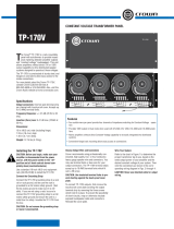
y LED indicators (panels with LED display; Figure 1)
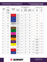
y Advanced LCD display (panels with meter module; Figure 2)
y Alarm Contacts: Form C dry contacts
y Side-accessible modular jack connections for alarm outputs
y Polarized, positive latching connectorized outputs
y Optional lacing bar kit (C750-283-10) or telescoping rear rack
support kit (C750-277-10)
Figure 1. LED display
Figure 2. Meter module

6
C048-784-30 R01, Rev. B (03/2021)
3.0 3.0 Unpacking and InspectionUnpacking and Inspection
The TPA 250 Series fuse panel was carefully packaged at the factory to withstand the normal rigors of shipping� However,
you should carefully inspect the box and contents to conrm that no damage has occurred in transit. Most shipping
carriers require notication of shipping damage within twenty-four hours of delivery, and it is the responsibility of the
recipient to inspect the shipment immediately upon receipt�
3.1 3.1 Package ContentsPackage Contents
Included with your product are the following items:
y TPA 250 Series fuse panel
y Mounting hardware kit
y Optional lacing bar kit or rear rack support kit (if ordered)
4.0 4.0 InstallationInstallation
4.1 4.1 Installation PreparationInstallation Preparation
When selecting an installation location, ensure that all of the following conditions are met before proceeding�
4.1.1 4.1.1 Elevated Operating Ambient TemperatureElevated Operating Ambient Temperature
If you install the panel in a closed or multi-unit rack assembly, the operating ambient temperature of the rack environment
may be greater than room ambient� Therefore, take care to install the equipment in an environment compatible with the
maximum ambient temperature (TMA)�
4.1.2 4.1.2 Reduced Air FlowReduced Air Flow
Installation of the equipment in a rack should be such that the amount of air ow required for safe operation of the
equipment is not compromised�
4.1.3 4.1.3 Mechanical LoadingMechanical Loading
Mounting of the equipment in the rack should be such that a hazardous condition is not achieved due to uneven
mechanical loading�
4.1.4 4.1.4 Circuit OverloadingCircuit Overloading
Give consideration to the connection of the equipment to the supply circuit and the eect that overloading of the circuits
might have on overcurrent protection and supply wiring� Use appropriate consideration for equipment nameplate ratings
when addressing this concern�
4.1.5 4.1.5 Reliable EarthingReliable Earthing
Maintain reliable earthing of rack-mounted equipment� Pay particular attention to supply connections other than direct
connections to the branch circuit (e�g�, use of power strips)�
4.1.6 4.1.6 Disconnect DeviceDisconnect Device
A readily accessible disconnect device must be incorporated in the building installation wiring�

7
C048-784-30 R01, Rev. B (03/2021)
4.2 4.2 MountingMounting
THIS PRODUCT MUST BE INSTALLED WITHIN A
RESTRICTED ACCESS LOCATION WHERE ACCESS IS
THROUGH THE USE OF A TOOL, LOCK AND KEY, OR
OTHER MEANS OF SECURITY, AND IS CONTROLLED
BY THE AUTHORITY RESPONSIBLE FOR THE
LOCATION� THIS PRODUCT MUST BE INSTALLED AND
MAINTAINED ONLY BY QUALIFIED TECHNICIANS�
SUITABLE FOR MOUNTING ON CONCRETE OR OTHER
NON-COMBUSTIBLE SURFACE ONLY�
NOTICE:
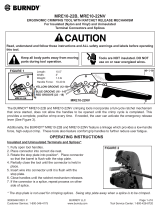
The TPA 250 Series fuse panel can be mounted in a front ush mount
conguration, a mid-mount forward conguration, or a mid-mount
rearward conguration. Depending on the desired conguration, attach
the mounting ears accordingly (see Figure 3)�
Step 1. Attach the mounting ears with included 10-32 hardware (see
Figure 4)�
Step 2. Select the equipment rack location for installation of the fuse
panel then secure the panel to the equipment rack by tightening
hardware into the mounting ears�
4.2.1 4.2.1 Optional Cable Lacing Bar Kit Optional Cable Lacing Bar Kit (C750-283-10)(C750-283-10)
Step 1. Install the cable lacing rod in between the left and right lacing
bar brackets by tightening a supplied 10-32 socket head screw
into each end of the threaded rod (see Figure 5)�
Step 2. Attach the cable lacing bar assembly to the fuse panel by
tightening (2) 10-32 socket head screws per side into the
threaded holes located on each side of the fuse panel chassis
towards the rear (see Figure 6)�
Figure 3. Mounting ear positions
Figure 4. Mounting ears (position 1 shown)
Figure 5. Cable lacing rod
Figure 6. Cable lacing bar assembly install

8
C048-784-30 R01, Rev. B (03/2021)
4.2.2 4.2.2 Optional Rear Rack Support Kit Optional Rear Rack Support Kit (C750-277-10)(C750-277-10)
An optional telescoping rear rack support kit is available to help secure
the panel to the rear of the equipment rack and to distribute panel weight
evenly� In addition to the standard lacing bar included with the TPA 250
Series fuse panel, a new lacing bar is included with this kit which can be
repositioned on any of the available lacing bar holes depending on the
depth of the equipment rack� Use a hex key to relocate the new lacing
bar if needed� See Appendix A for mechanical dimensions of rear rack
support kit�
Step 1. Install the shorter cable lacing rod in between the left and right
lacing bar brackets by tightening a supplied 10-32 socket head
screw into each end of the threaded rod (see Figure 5 on Page 7)�
Step 2. Attach the cable lacing bar assembly to the fuse panel by
tightening (2) 10-32 socket head screws per side into the
threaded holes located on each side of the fuse panel chassis
towards the rear (see Figure 6 on Page 7)�
Step 3. Install the longer cable lacing rod in between the left and right
lacing bar rear support rails by tightening a supplied 10-32 socket
head screw into each end of the threaded rod (see Figure 7)�
Multiple mounting holes are provided in the rails for optimal lacing
rod positioning�
Step 4. Slide the rails of the rear rack support assembly into the lacing
bar assembly (see Figure 8)�
Step 5. Secure the mounting ears to equipment rack via the slotted holes
or threaded inserts�
4.3 4.3 Chassis GroundChassis Ground
DO NOT ENERGIZE THE PANEL BEFORE CHASSIS
GROUND IS CONNECTED�
CAUTION!
WARNING! ELECTRICAL HAZARD
DO NOT USE HARDWARE WITH A LENGTH EXCEEDING
3/4 INCH FOR CHASSIS GROUND CONNECTIONS�
The chassis ground is located on both sides of the panel� Two-hole
lug landing positions are provided� See table below for termination
information� A minimum of #4 AWG chassis ground cable is required�
IMPORTANT: Grounding hardware not included. A properly-sized
grounding conductor must be installed per NEC (250�122)�
Table 2. Chassis Ground Termination Specications
TERMINATION
TYPE
HOLE/STUD
SIZE
CENTER
TO CENTER
RECOMMENDED
TORQUE VALUE
Threaded insert 1/4 in� 5/8 in� 6.25 ft∙lbs
Step 1. Secure the ground cable to the chassis by tightening 1/4 in�
hardware (see Figure 9)�
Figure 7. Cable lacing rod
(for rear rack support kit)
Figure 8. Rear support rails
(for rear rack support kit)
Figure 9. Chassis ground

9
C048-784-30 R01, Rev. B (03/2021)
4.4 4.4 Input ConnectionsInput Connections
WARNING! ELECTRICAL HAZARD
MULTIPLE POWER SOURCES ARE PRESENT, ENSURE ALL INPUT POWER FEEDS ARE NOT
ENERGIZED BEFORE INSTALLING THEM� ELECTRICAL INSTALLATION SHOULD ONLY BE
PERFORMED BY QUALIFIED PERSONNEL WITH PROPER TOOLS AND PROTECTIVE SAFETY
EQUIPMENT�
INPUTS MUST BE PROTECTED BY A LISTED CIRCUIT BREAKER OR BRANCH RATED FUSE� THE CIRCUIT
BREAKER OR FUSE MUST BE RATED AT 125% OF THE PANEL RATING�
MAKE SURE THAT ALL FEEDER CABLES HAVE HEAT SHRINK APPLIED PRIOR TO TERMINATION,
AND THAT NO-OXIDE COMPOUND IS APPLIED TO ALL COPPER-TO-COPPER CONNECTIONS�
SEE SECTION 7 ON PAGE 13 FOR COMPRESSION LUG SPECIFICATIONS, TOOLING, AND ORDERING
INFORMATION�
NOTICE:
Table 3. Input Termination Specications
TERMINATION
TYPE
HOLE/
STUD
SIZE
CENTER TO
CENTER
RECOMMENDED
TORQUE VALUE
Threaded stud 1/4 in� 5/8 in� 6.25 ft∙lbs
Step 1. Secure the RTN input cables/lugs to the RTN input studs
located on the rear of the panel (see Figure 10)� Ensure that
all hardware is tightened�
Step 2. Secure the HOT input cables/lugs to the HOT input studs
located on the rear of the panel (see Figure 11)� Ensure that
all hardware is tightened�
4.4.1 4.4.1 Safety CoversSafety Covers
WARNING! ELECTRICAL HAZARD
FAILURE TO INSTALL THE PLASTIC SAFETY COVERS
PROPERLY MAY CREATE AN ELECTRICAL HAZARD�
Included with each TPA 250 Series product are (4) input safety
covers that are designed to help isolate the input terminations�
Step 1. Align the notch found on the included plastic safety covers
with the slots located at the rear of the panel�
Step 2. Firmly insert into place until fully seated (see Figure 12)�
Figure 10. RTN input
Figure 11. HOT input
Figure 12. Safety covers

10
C048-784-30 R01, Rev. B (03/2021)
4.5 4.5 Output ConnectionsOutput Connections
DO NOT PERFORM THIS STEP ON CIRCUITS WITH FUSES
INSTALLED� ENSURE NO POWER IS PRESENT ON THE
CIRCUIT BEING WIRED BEFORE PROCEEDING�
CAUTION!
SEE SECTION 7 ON PAGE 13 FOR TERMINAL
SPECIFICATION AND CABLE WHIP ORDERING
INFORMATION�
NOTICE:
There are twelve positive latching DC connector positions for the output circuits found on the TPA 250 Series fuse panel,
available in either 37A or 100A connector congurations. Cable whips are available in a variety of lengths and wire
gauges� Refer to the front of the panel for the circuit mapping card for circuit mapping information�
Step 1. Insert the DC plugs into the output receptacles until they click� The connectors are keyed to ensure correct polarity
(see Figure 13)�
Figure 13. Output connections
4.6 4.6 Fuse InstallationFuse Installation
USE BUSSMANN TPA TYPE FUSES ONLY� FUSES MUST
CARRY A 10KA OR HIGHER INTERRUPT RATING�
NOTICE:
Step 1. Ensure that connected loads are in the o position, then rmly
insert a TPA fuse of sucient ampacity into the position to be fed
(see Figure 14)�
Step 2. Turn on the connected load�
4.7 4.7 Alarm ConnectionsAlarm Connections
WHEN DAISY CHAINING, THE ALARM MUST BE
MONITORED NORMALLY OPEN�
NOTICE:
The TPA 250 Series fuse panel has Form-C dry alarm contacts for
remote alarm monitoring� If alarm monitoring is required, (2) 8p8c (RJ-
45) modular jacks are provided for alarm connections� The (2) jacks
support easy daisy chaining of panels� The 8p8c modular jacks are
located on the left side of the panel� Refer to mechanical drawings
found in Appendix A for more details�
Step 1. Plug in a UTP cable with a TIA/EIA T568B termination into the
alarm jack (see Figure 15)� Refer to Table 4 for alarm pinout information�
Step 2. Connect the cable to the site alarm monitoring system�
Step 3. If daisy chaining is required, connect a UTP cable with TIA/EIA T568B termination into the second jack and
connect the other end to the next panel in the chain� Repeat this process until all panels are connected�
Table 4. Alarm Contact Pinout
PIN 1 PIN 2 PIN 3 PIN 4-8
MAJOR COM MAJOR NC MAJOR NO Reserved
Figure 14. TPA fuse installation
Figure 15. Alarm connections

11
C048-784-30 R01, Rev. B (03/2021)
5.0 5.0 OperationOperation
5.1 5.1 LED DisplayLED Display
Modules with the LED display include three indicators:
y A Power
y B Power
y Alarm
5.1.1 5.1.1 A Power LEDA Power LED
The A Power LED will illuminate when power is present on the A input
bus�
5.1.2 5.1.2 B Power LEDB Power LED
The B Power LED will illuminate when power is present on the B input
bus�
5.1.3 5.1.3 Alarm LEDAlarm LED
The Alarm LED will illuminate if a fuse is blown�
Figure 16. LED Status Display

12
C048-784-30 R01, Rev. B (03/2021)
6.0 6.0 Product SpecicationsProduct Specications
USE BUSSMANN
®
TPA TYPE FUSES ONLY�
FUSES MUST CARRY A 10KA INTERRUPT RATING�
NOTICE:
Table 5. Technical Specications
C016-2121-10,
C016-2123-10,
C016-2125-10,
C016-2127-10
C016-2122-10,
C016-2124-10,
C016-2126-10,
C016-2128-10
Type of Input Single Input Dual Input (A/B)
Circuits 12 12 (6A/6B)
Input Voltage -42 to -60V DC -42 to -60V DC
Input Current 250A Max 250A Max
Short Circuit Withstand 10kA 10kA
Maximum Fuse Size 50A TPA 50A TPA
Maximum per Circuit Current 40A 40A
Max Operating Altitude 2000 m 2000 m
Max Ambient Temperature 50º C 50º C
Width 17 in� 17 in�
Height 1�75 in� 1�75 in�
Depth (w/o Lacing Bar Kits) 18 in� 18 in�
Weight 8�5 lbs� 8�5 lbs�
BUSSMANN
®
is a registered trademark of Cooper Technologies Company.
Table 6. Agency Certications
UL
UL File Number E473904
UL Standard ANSI/UL 60950-1

13
C048-784-30 R01, Rev. B (03/2021)
7.0 7.0 Models and AccessoriesModels and Accessories
Table 7. Model Congurations
DESCRIPTION PART NUMBER
Single Input, (12) 50A Max TPA Fuse Positions, Connectorized Outputs, 37A Max per Output,
250A Continuous Output Capacity, -48VDC, LED Display
C016-2121-10
Dual Input, 6A/6B 50A Max TPA Fuse Positions, Connectorized Outputs, 37A Max per Output,
250A Continuous Output Capacity, -48VDC, LED Display
C016-2122-10
Single Input, (12) 50A Max TPA Fuse Positions, Connectorized Outputs, 37A Max per Output,
250A Continuous Output Capacity, -48VDC, Meter Module Display
C016-2123-10
Dual Input, 6A/6B 50A Max TPA Fuse Positions, Connectorized Outputs, 37A Max per Output,
250A Continuous Output Capacity, -48VDC, Meter Module Display
C016-2124-10
Single Input, (12) 50A Max TPA Fuse Positions, Connectorized Outputs, 100A Max per Output,
250A Continuous Output Capacity, -48VDC, LED Display
C016-2125 -10
Dual Input, 6A/6B 50A Max TPA Fuse Positions, Connectorized Outputs, 100A Max per Output,
250A Continuous Output Capacity, -48VDC, LED Display
C016-2126-10
Single Input, (12) 50A Max TPA Fuse Positions, Connectorized Outputs, 100A Max per Output,
250A Continuous Output Capacity, -48VDC, Meter Module Display
C016-2127-10
Dual Input, 6A/6B 50A Max TPA Fuse Positions, Connectorized Outputs, 100A Max per Output,
250A Continuous Output Capacity, -48VDC, Meter Module Display
C016-2128-10
Table 8. Accessories
DESCRIPTION PART NUMBER
Lacing Bar Kit; TPA 250 Series Fuse Panel C750-283-10
Adjustable Rear Mounting Kit with Lacing Bars; TPA 250 Series Fuse Panel C750-277-10
Table 9. Supported TPA Fuses
DESCRIPTION
3A TPA Fuse; DC-170V; .58" x 1.5" C460-060-10
5A TPA Fuse; DC-170V; .58" x 1.5" C460-061-10
10A TPA Fuse; DC-170V; .58" x 1.5" C460-062-10
15A TPA Fuse; DC-170V; .58" x 1.5" C460-063-10
20A TPA Fuse; DC-170V; .58" x 1.5" C460-064-10
25A TPA Fuse; DC-170V; .58" x 1.5" C460-065-10
30A TPA Fuse; DC-170V; .58" x 1.5" C460-066-10
40A TPA Fuse; DC-170V; .58" x 1.5" C460-067-10
50A TPA Fuse; DC-170V; .58" x 1.5" C460-068-10
Table 10. Supported Lugs for Chassis Ground Connections
WIRE
GAUGE
LUG
BARREL
ALPHA PART
NUMBER
MANUFACTURER MANUFACTURER
PART NUMBER
CRIMP DIE REQUIRED
#4 Long C538-085 -10 Burndy
®
YAZ V4C2TC14FX Burndy U4CRT, W4CVT, W4CRT,
X4CRT
Table 11. Supported Lugs for Input Connections
WIRE
GAUGE
LUG
BARREL
ALPHA PART
NUMBER
MANUFACTURER MANUFACTURER
PART NUMBER
CRIMP DIE REQUIRED
#2 AWG Short;
narrow
tongue
C538-173-10 Burndy
®
YAV2CL2NT14FX Burndy U2CRT, W2CVT, W2CRT,
X2CRT
#2 AWG Standard C538-158-10 Burndy
®
YAV2CL2TC14FX Burndy U2CRT, W2CRT, W2CVT,
X2CRT
#2 AWG Long C538- 089-10 Burndy
®
YAZV2C2TC14FX Burndy U2CRT, W2CVT, W2CRT,
X2CRT

14
C048-784-30 R01, Rev. B (03/2021)
WIRE
GAUGE
LUG
BARREL
ALPHA PART
NUMBER
MANUFACTURER MANUFACTURER
PART NUMBER
CRIMP DIE REQUIRED
1/0 Short C538-350-10 Burndy
®
YAV25L2TC14FX Burndy U25RT, W25VT, W25RT,
X25RT
1/0 Standard C538-125-10 Burndy
®
YAV25L2NT14FX Burndy U25RT, W25VT, W25RT,
X25RT
1/0 Long C538-091-10 Burndy
®
YAZ V252TC14FX Burndy U25RT, W25VT, W25RT,
X25RT
1/0 Long;
narrow
tongue
C538-260-10 Burndy
®
YAZ V252NT14FX Burndy U25RT, W25RT, X25RT,
W25VT
2/0 Short C538 -357-10 Burndy
®
YAV26L2TC14FX Burndy U26RT, W26VT, W26RT,
X26RT
2/0 Standard C538-313-10 Burndy
®
YAV26L2NT14FX Burndy U26RT, W26VT, W26RT,
X26RT
2/0 Long C538-114-10 Burndy
®
YAZV262TC14FX Burndy U26RT, W26VT, W26RT,
X26RT
4/0 Short C538-410-10 Burndy
®
YAV28L2TC14FX Burndy U28RT, W28VT, W28RT,
X28RT
4/0 Standard C538-124-10 Burndy
®
YAV28L2ENT14FX Burndy U28RT, W28VT, W28RT,
X28RT
4/0 Long C538-122-10 Burndy
®
YAZV282TC14FX Burndy U28RT, W28VT, W28RT,
X28RT
BURNDY® is the registered trademark of Hubbell Incorporated.
Table 12. 37A Output Connectorized Cable Assemblies
(For C016-2121-10, C016-2122-10, C016-2123-10, C016-2124-10 Models)
AWG LENGTH COLOR PART NUMBER
#10 7’ Red/Black C745 - 420-10
Blue/Black C745 - 422-10
Red/Red Tracer C745-437-10
Blue/Blue Tracer C745-433-10
12’ Red/Black C745 -290 -10
Blue/Black C745 - 424 -10
Red/Red Tracer C745-438-10
Blue/Blue Tracer C745-434-10
#12 7’ Red/Black C745 - 421-10
Blue/Black C745-425-10
Red/Red Tracer C745 -298 -10
Blue/Blue Tracer C745 -299 -10
12’ Red/Black C745 -293-10
Blue/Black C745 -294 -10
Red/Red Tracer C745 -197-10
Blue/Blue Tracer C745-198-10
#14 7’ Red/Black C745-436-10
Blue/Black C745 - 427-10
Red/Red Tracer C745-432-10
Blue/Blue Tracer C745-435-10
12’ Red/Black C745 -296 -10
Blue/Black C745 - 429-10
Red/Red Tracer C745 -227-10
Blue/Blue Tracer C745 -228-10

15
C048-784-30 R01, Rev. B (03/2021)
Table 13. 100A Output Connectorized Cable Assemblies
(For C016-2125-10, C016-2126-10, C016-2127-10, C016-2128-10 Models)
AWG LENGTH COLOR PART NUMBER
#6 7’ Red/Black C745 - 400 -10
Blue/Black C745 - 461-10
Red/Red Tracer C745-263-10
Blue/Blue Tracer C745 -264-10
12’ Red/Black C745 -377-10
Blue/Black C745 -382-10
Red/Red Tracer C745-235-10
Blue/Blue Tracer C745 -236-10
#8 7’ Red/Black C745 - 401-10
Blue/Black C745 - 407-10
Red/Red Tracer C745-410-10
Blue/Blue Tracer C745 - 414-10
12’ Red/Black C745 -376-10
Blue/Black C745 -381-10
Red/Red Tracer C745 -233 -10
Blue/Blue Tracer C745 -234-10
#10 7’ Red/Black C745 - 402-10
Blue/Black C745 - 408 -10
Red/Red Tracer C745 - 411-10
Blue/Blue Tracer C745-415-10
12’ Red/Black C745-375-10
Blue/Black C745-380-10
Red/Red Tracer C745 - 418 -10
Blue/Blue Tracer C745 - 419 -10
#12 7’ Red/Black C745 - 403 -10
Blue/Black C745 - 409 -10
Red/Red Tracer C745 - 412-10
Blue/Blue Tracer C745 - 416 -10
12’ Red/Black C745 -374-10
Blue/Black C745 -379 -10
Red/Red Tracer C745 - 413-10
Blue/Blue Tracer C745 - 417-10
#14 7’ Red/Black C745 - 462-10
Blue/Black C745-463-10
Red/Red Tracer C745 - 464-10
Blue/Blue Tracer C745-465-10
12’ Red/Black C745 -373 -10
Blue/Black C745 -378-10
Red/Red Tracer C745-458-10
Blue/Blue Tracer C745-459-10

16
C048-784-30 R01, Rev. B (03/2021)
Appendix A: Appendix A: Mechanical DrawingsMechanical Drawings
A.1 A.1 Front/Rear DetailFront/Rear Detail
FRONT VIEW
1.720
LED MODULE
METER MODULE
1.000
RETURN
HOT HOT
RETURN
A INPUT
B INPUT
100A CONNECTORIZED OUTPUTS
40A CONNECTORIZED OUTPUTS
REAR VIEW

17
C048-784-30 R01, Rev. B (03/2021)
A.2 A.2 Left/Right DetailLeft/Right Detail
SIDE VIEW

18
C048-784-30 R01, Rev. B (03/2021)
A.3 A.3 Top DetailTop Detail
TOP VIEW
17.000
18.000
16.000

19
C048-784-30 R01, Rev. B (03/2021)
A.4 A.4 Rear Support Kit - Minimum Depth (C750-277-10)Rear Support Kit - Minimum Depth (C750-277-10)
REAR SUPPORT KIT
(MINIMUM DEPTH)

20
C048-784-30 R01, Rev. B (03/2021)
A.5 A.5 Rear Support Kit - Maximum Depth (C750-277-10)Rear Support Kit - Maximum Depth (C750-277-10)
REAR SUPPORT KIT
(MAXIMUM DEPTH)
/