ADTRAN TRACER 6000 Operating instructions

Type
Operating instructions

ADTRAN TRACER 6000 is a versatile and powerful device designed to meet the demands of modern communication networks. It features advanced capabilities that enable efficient and reliable data transmission and distribution. With its robust construction and comprehensive functionalities, the TRACER 6000 is ideal for various applications, including:

  • High-speed data transmission: The TRACER 6000 supports high-bandwidth data transmission, making it suitable for applications requiring fast and seamless data transfer.

  • Reliable network connectivity: The device ensures reliable network connectivity by providing features like redundancy and load balancing, minimizing downtime and enhancing network stability.

For more detailed documentation, visit us online at www.adtran.com
Quick Start Guide
®
TRACER 60000 Series Grounding Instructions
Quick Start Guide, 612806420L1-13A, March 2006 Copyright © 2006 ADTRAN, All Rights Reserved
TRACER 6410 Rear Panel
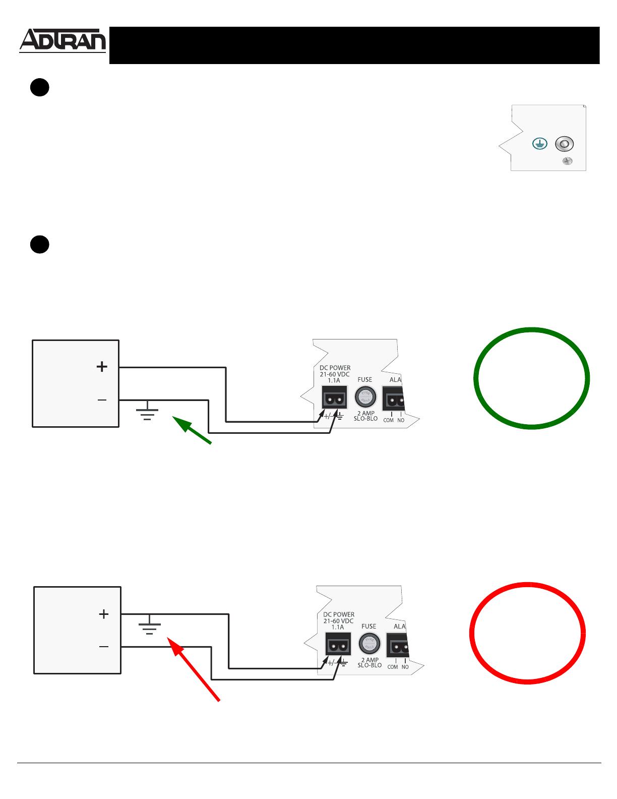
In this scenario, the grounded leg of a grounded power supply is connected to the power pin (+/–) of the TRACER
power terminal block. In this case, the difference in potential between the two grounds cause a ground loop that
blows the TRACER internal fuse.
NO
The grounded leg of the power supply is connected to the
power pin (+/–) of the TRACER power terminal block. This
creates two ground potentials in this power loop. The
resulting ground loop blows the internal fuse.
DC
Source
Power
The ground pin of the TRACER power terminal block is internally connected to chassis
ground. It is important to consider this when connecting the chassis ground lug (see Figure 1)
to Earth ground. To avoid problems, the same Earth ground source should be used for all
equipment connected to the power system (including the DC power source). Connect the
ground lug (see Figure 1) to Earth ground using a number 8 ring terminal before supplying
power to the unit. The ring terminal should be installed using the appropriate crimping tool
(AMP P/N 59250 T-EAD Crimping Tool or equivalent). A difference in potential between
multiple ground sources causes a ground loop that will blow the internal fuse. Units must be
returned to ADTRAN for internal fuse replacement.
1
Connecting Earth Ground
FIGURE 1
Determining the Power Configuration
2
TRACER 6410 Rear Panel
Configuration 1: In this scenario, the grounded leg of a grounded power supply is connected to the ground pin of
the TRACER power terminal block. In this case, the ground potential of the power supply should be the same as the
ground potential of the TRACER system.
The grounded leg of the power supply is connected to the
same ground source as the TRACER system. Negligible
difference in potential between the grounds allows power to
flow properly.
YES
DC
Source
Power
Quick Start Guide, 612806420L1-13A, March 2006 Copyright © 2006 ADTRAN, All Rights Reserved
TRACER 6410 Rear Panel
Other Equipment
Configuration 2: In this scenario, the DC power source is ungrounded (floating). Other equipment connected to the
same power source is grounded and connected to the same terminal on the power source as the ground pin of the
TRACER power terminal block. The other equipment could also be floating, allowing the TRACER ground to act as
the single ground source for the power system.
The grounded leg of the other
equipment is connected to the
same DC power terminal (–) as
the grounded leg of the
TRACER system. Negligible
difference in potential between
the grounds allows power to
flow properly.
YES
DC
Source
Power
TRACER 6410 Rear Panel
Other Equipment
In this scenario, the DC power source is ungrounded (floating). Other equipment connected to the same power source
is grounded and connected to the opposite terminal on the power source as the ground pin of the TRACER power
terminal block. In this case, the difference in potential between the two grounds cause a ground loop that blows the
TRACER internal fuse.
Ground leg of other equipment is
connected to the (+) terminal of the DC
power source.
NO
Ground leg of TRACER power terminal
block is connected to the (–) terminal
of the DC power source.
DC
Source
Power
IMPORTANT!!
READ THESE INSTRUCTIONS CAREFULLY
BEFORE INSTALLING YOUR TRACER SYSTEM.
  • Page 1 1
  • Page 2 2

ADTRAN TRACER 6000 Operating instructions

Type
Operating instructions

ADTRAN TRACER 6000 is a versatile and powerful device designed to meet the demands of modern communication networks. It features advanced capabilities that enable efficient and reliable data transmission and distribution. With its robust construction and comprehensive functionalities, the TRACER 6000 is ideal for various applications, including:

  • High-speed data transmission: The TRACER 6000 supports high-bandwidth data transmission, making it suitable for applications requiring fast and seamless data transfer.

  • Reliable network connectivity: The device ensures reliable network connectivity by providing features like redundancy and load balancing, minimizing downtime and enhancing network stability.

Ask a question and I''ll find the answer in the document

Finding information in a document is now easier with AI