Page is loading ...

Trinity i875P S5101 User’s Manual
i
http://www.tyan.com
Trinity i875P
///
S5101
Revision 1.01
Copyright © TYAN Computer Corporation, 2003. All rights reserved. No part of this manual
may be reproduced or translated without prior written consent from TYAN Computer Corp.
All registered and unregistered trademarks and company names contained in this manual are
property of their respective owners including, but not limited to the following.
TYAN, Trinity, i875P and S5101 are trademarks of TYAN Computer Corporation.
Intel, Pentium 4, and combinations thereof are trademarks of Intel Corporation.
VIA, VT6307,are trademarks of VIA Technologies, Inc.
Promise is a trademark of Promise Technology, Inc.
Award, AwardBIOS are trademarks of Award Software Incorporated.
Microsoft and Windows are trademarks of Microsoft Corporation.
IBM, PC, AT and PS/2 are trademarks of IBM Corporation.
Winbond is a trademark of Winbond Electronics Corporation.
Sony/Philips Digital Interface (SPDIF) is a trademark of Sony Corporation and Philips
Electronics.
Portable Document Format (PDF) is a trademark of Adobe Corporation.
Information contained in this document is furnished by TYAN Computer Corporation and has
been reviewed for accuracy and reliability prior to printing. TYAN assumes no liability
whatsoever, and disclaims any express or implied warranty, relating to sale and/or use of
TYAN products including liability or warranties relating to fitness for a particular purpose or
merchantability. TYAN retains the right to make changes to product descriptions and/or
specifications at any time, without notice. In no event will TYAN be held liable for any direct or
indirect, incidental or consequential damage, loss of use, loss of data or other malady resulting
from errors or inaccuracies of information contained in this document.

Trinity i875P S5101 Table of Contents
ii
http://www.tyan.com
Table of Contents
Before you begin… ................................................................................................................. iii
Chapter 1: Introduction.........................................................................................................1-1
1.1 – Congratulations! ...................................................................................................... 1-1
1.2 – Hardware Specifications ......................................................................................... 1-1
Chapter 2: Board Installation ............................................................................................... 2-1
2.1 – Board Image ........................................................................................................... 2-2
2.2 – Board Parts ............................................................................................................. 2-3
2.3 – Block Diagram......................................................................................................... 2-4
2.4 – Jumper Settings & Definitions.................................................................................2-5
2.5 – Connector Description ............................................................................................ 2-7
2.6 – Mounting the Motherboard .................................................................................... 2-14
2.7 – Installing the Memory............................................................................................2-15
2.8 – Memory Installation Procedure ............................................................................. 2-16
2.9 – Installing the Processor and Heatsink................................................................... 2-17
2.10 – Attaching Drive Cables ....................................................................................... 2-19
2.11 – Installing Add-In Cards........................................................................................ 2-22
2.12 – Connecting External Devices..............................................................................2-23
2.13 – Installing the Power Supply................................................................................. 2-24
2.14 – Finishing Up ........................................................................................................ 2-24
Chapter 3: BIOS Setup..........................................................................................................3-1
3.1 – Main BIOS Setup .................................................................................................... 3-3
3.2 – Standard CMOS Features ...................................................................................... 3-5
3.3 – Advanced BIOS Features ....................................................................................... 3-7
3.4 – Advanced Chipsets Features................................................................................ 3-10
3.5 – Integrated Peripherals........................................................................................... 3-12
3.6 – Power Management Setup ................................................................................... 3-17
3.7 – PnP/PCI Configurations ........................................................................................ 3-21
3.8 – PC Health Status .................................................................................................. 3-22
3.9 – Frequency/Voltage Control ................................................................................... 3-23
3.10 – Load Fail-Safe Defaults ...................................................................................... 3-24
3.11 – Load Optimized Defaults..................................................................................... 3-25
3.12 – Supervisor/User Password Setting ..................................................................... 3-26
3.13 – Exit Selecting ...................................................................................................... 3-27
Chapter 4: SATA/RAID Setup (for SATA RAID model) ...................................................... 4-1
4.1 – Getting Started........................................................................................................ 4-1
4.2 - Creating Your Disk Array ......................................................................................... 4-2
4.3 - Installing Software Drivers ....................................................................................... 4-6
4.4 - Using FastBuild™ Configuration Utility.................................................................... 4-9
Chapter 5: Diagnostics ......................................................................................................... 5-1
5.1 Beep Codes ............................................................................................................... 5-1
5.2 Flash Utility.................................................................................................................5-1
Appendix I: Glossary ............................................................................................................6-1
Appendix II: Post Error Code for BIOS ............................................................................... 6-7
Technical Support .......................................................................................................... 6-12

Trinity i875P S5101 Before you begin…
iii
http://www.tyan.com
Before you begin…
Check the box contents!
The retail motherboard package should contain the following:
1x Trinity i875P S5101 motherboard
1x 34-Pin floppy drive cable
1x Ultra-DMA-133/100/66/33 IDE cable
1x Ultra-DMA-133/100/66/33 IDE cable
(only for models with Promise RAID )
1x Trinity i875P S5101 User’s Manual
1x Trinity i875P S5101 Quick Reference Guide
1x TYAN driver CD
1x I/O shield
1 x Promise FastTrak 378 RAID Driver Diskette and
1x Promise SATA 378 Ultra ATA Driver (Optional)
1 x Game Port cable
1 x Serial ATA power cable (One additional for IDE RAID)
2 x Serial ATA cable (Two additional for IDE RAID)
1 x IEEE1394 cable
1 x USB2.0 cable
If any of these items are missing, please contact your vendor/dealer for replacement before
continuing with the installation process.

Trinity i875P S5101 Chapter 1: Introduction
1-1
http://www.tyan.com
Chapter 1: Introduction
1.1 – Congratulations!
You have purchased one of the most powerful solutions for the Intel Pentium
4 processor, the
Trinity i875P S5101 Based on Intel 875P chipsets, the main features of the Trinity i875P
S5101 are: ATX form factor, onboard GbE LAN port, and 6-channel audio. It also offers
optional features such as Serial ATA and IDE RAID for desktop demands.
Remember to visit TYAN’s Website at http://www.tyan.com
. There you can find information on
all of TYAN’s products with FAQs, distributors list, and BIOS setting explanations.
1.2 – Hardware Specifications
Processors
• Socket 478 processor
• Supports single Intel Pentium
4 processor
• Onboard VRM10 and FMB2
• Front-Side Bus support for 800/533/400MHz
Chipset
• Intel 875P North Bridge chipset
• Intel ICH5 South Bridge chipset
• Winbond W83627HF LPC I/O chip
Memory
• Four 184-pin DIMM sockets
• Supports DDR 400/333/266
• Up to 4GB of Un-buffered ECC and non-
ECC type memory modules
• Registered Memory is NOT supported
Integrated LAN Controller(s) (Optional)
• One 10/100 LAN controller
Realtek RTL8100C LAN controller
• Operating at 32-bit 33MHz PCI bus
• One Gigabit LAN controller Intel 82547 EI
(Optional)
Operating at 266MB/s CSA interface
Intelligent Audio
• ALC650 6-Channel AC97 audio CODEC
• Line-in / Speaker-out / MIC-in phone jacks
• CD-in / Aux-in connectors
• SPDIF output connector
Integrated Serial ATA (ICH5)
• Two Serial ATA Host controllers embedded
in ICH5
• Support two Serial ports running at 150MB/s
Integrated PCI IDE (ICH5)
• Dual channel master mode support up
to four IDE devices
• Support for ATA-100 / 66/ 33 IDE drives
and ATAPI compliant devices
Integrated PCI IEEE1394a Controller
• VIA VT6307 PCI IEEE1394a controller
• Support two IEEE1394a ports
Integrated I/O Interface
• One floppy connector supports up to
two drives
• Two SATA ports, eight USB2.0 ports
(4 ports by pin header)
• One game port (via optional cable)
• 2 x 5 pin header for front panel audio
connector
• One IrDA connector
• Power/IDE LED connectors
• Headers for CPU/Power Supply/Chassis
Fans
Rear Panel I/O ports
• Stacked PS/2 Mouse & Keyboard ports
• Stacked two USB2.0 ports and one
RJ45 LAN port on top
• One parallel and two Serial ports
• Stacked two USB 2.0 ports and one
RJ45 LAN (10/100/1000Mbps) port on
top (optional)
• Vertical Mic-In/Line-Out audio jacks
Expansion Slots
• Six 32-bit / 33MHz PCI 2.3 slots
• One 1.5V 8X/4X AGP Pro50 slot

Trinity i875P S5101 Chapter 1: Introduction
1-2
http://www.tyan.com
Integrated Serial ATA RAID (Optional)
• Promise PDC20378 SATA RAID controller
• Two Serial ATA RAID ports and one Ultra
ATA/133 IDE RAID port
• Support up to two SATA and two
ATA-133/100 IDE drives
• Supports IDE RAID 0, 1, 0+1(Need to install
two SATA Hard drivers and two ATA-
133/100 IDE drives simultaneously)
BIOS
• Award BIOS 4Mbit Flash ROM
• Support APM 1.2 & ACPI 1.0B
• PnP, DNI 2.0, WFM 2.0 Power Management
• Jumper free for System over clocking and
over voltage for CPU / Memory / AGP
• Support BIOS Boot Specification v1.01
(BBS)
• Supports Watchdog timer ready and DMI
Power
• On board VRM, 3-phase PWM
• ATX 12V power connector
Regulatory
• EMI - CE, FCC Class B
Miscellaneous
• STR, Three fan connectors
Form Factor
• ATX footprint
• 305mm x 245mm (12” x 9.6”)
Note: TYAN reserves the right to add support or discontinue support for any OS with or
without notice.

Trinity i875P S5101 Chapter 2: Board Installation
2-1
http://www.tyan.com
Chapter 2: Board Installation
Installation
You are now ready to install your motherboard. The mounting holes pattern of the Trinity
i875P S5101 matches the ATX specification. Before continuing with installation, confirm that
your chassis supports a standard ATX motherboard.
How to install our products right…. the first time!
The first thing you should do read this user’s manual. It contains important information that
will make configuration and setup much easier. Here are some precautions you should take
when installing your motherboard:
(1) Ground yourself properly before removing your motherboard from the antistatic bag.
Unplug the power from your computer power supply and then touch a safely
grounded object to release static charge (i.e. power supply case). For the safest
conditions, TYAN recommends wearing a static safety wrist strap.
(2) Hold the motherboard by its edges and do not touch the bottom of the board, or flex
the board in any way.
(3) Avoid touching the motherboard components, IC chips, connectors, memory
modules and leads.
(4) Place the motherboard on a grounded antistatic surface or on the antistatic bag that
the board was shipped in.
(5) Inspect the board for damage.
The following pages include details on how to install your motherboard into your chassis, as
well as installing the processor, memory, disk drives and cables.
Note: DO NOT APPLY POWER TO THE BOARD IF IT HAS BEEN DAMAGED

Trinity i875P S5101 Chapter 2: Board Installation
2-2
http://www.tyan.com
2.1 – Board Image
The following is an image of the Trinity i875P S5101.
The above photograph is purely representative. Due to engineering updates and new
board revisions, certain components may change and or be repositioned. The picture
above may or may not look exactly like the board you received.
The following page includes details on the vital components of this motherboard.

Trinity i875P S5101 Chapter 2: Board Installation
2-3
http://www.tyan.com
2.2 – Board Parts
S5101
USB3
1
1
1
1
1
KB-MO1
USB2
CN2 (COM1)CN3 (COM2)
CN4
(Parallel Port)
Power FAN
J14
PWR2
USB1
CN1
(Audio)
ALC650
SPDIF1
CPU FAN
J7
BIOS
J5
Intel
875P
Intel
ICH5
PCI2PCI3PCI4PCI5
SATA1
SATA2
FDD J13
JP1
BT1
SEC-IDE J10
PRI-IDE J11
1
J4
W83627HF
CN18
Realtek
LAN
PCI6
USB4
1
VIA
VT6307
LED2
PCI1
RAID-IDE1 J12
SATA3
(Optional)
SATA4
Chassis
FAN
1
CD_IN1
1
AUX_IN1
PDC20378
(Optional)
(Optional)
J2
1
J3
1
2
J6
(Optional)
1
J9
Intel
LAN
(Optional)
LED1
1
1
A
GP
USB (Bottom)
LAN (Top)
USB (Bottom)
LAN (Top)Optional
KB(Bottom)
Mouse(Top)
This jumper diagram is representative of the latest board revision available at the time
of publishing. The board you receive may or may not look exactly like the above
diagram. The board parts are not to scale.

Trinity i875P S5101 Chapter 2: Board Installation
2-4
http://www.tyan.com
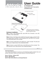
2.3 – Block Diagram
The following is a block diagram of the Trinity i875P S5101.
mPGA478
Processor Socket
ICS-952607
VRD10.0
Intel 82875P MCH
Intel 82801EB
ICH5
DDR
DDR
DDR
DDR
AGP Pro50
8X/4X
3.0/2.0
CSA Interface
Gigabit
Ethernet
(Optional)
VIA IEEE1394a
VT6307
Winbond
W83627F/HF
LPC SIO
FirmWare Hub
Keyboard
Mouse
Floppy
Parallel
Serial 1/2
Game Connector
USB 2.0
8 ports, 480Mb/s
2 X Serial ATA
Ports 150MB/s
2 X ATA 100/66/
33 Ports
AC'97 Audio
Codec
Promise
PDC20378
RAID 0, 1, 0+1
(Optional)
2 X Serial ATA
RAID Ports
150MB/s
One ATA 133 IDE
RAID Ports
Realtek
10/100 MB LAN
800/533/400 MHz
System Bus
Intel 875P Chipset
Syatem Memory
DDR 400/333/266
Channel A
Channel B
266 MB/s
2.1 GB/s
Six PCI Masters
PCI BUS
LPC Interface
2 X IEEE1394a
Ports
266 MB/s
Hub Link 1.5
®
®
®

Trinity i875P S5101 Chapter 2: Board Installation
2-5
http://www.tyan.com
2.4 – Jumper Settings & Definitions
Jumper Function Ref. Page
JP1 Clear CMOS Page 2-5
Jumper Example
Jumper OFF – open (without jumper cap)
Jumper ON – closed (with jumper cap)
CMOS Reset (JP1)
JP1
S5101
USB3
1
1
1
1
1
KB-MO1
USB2
CN2 (COM1)CN3 (COM2)
CN4
(Parallel Port)
Power FAN
J14
PWR2
USB1
CN1
(Audio)
ALC650
SPDIF1
CPU FAN
J7
BIOS
J5
Intel
875P
Intel
ICH5
PCI2PCI3PCI4PCI5
SATA1
SATA2
FDD J13
JP1
BT1
SEC-IDE J10
PRI-IDE J11
1
J4
W83627HF
CN18
Realtek
LAN
PCI6
USB4
1
VIA
VT6307
LED2
PCI1
RAID-IDE1 J12
SATA3
(Optional)
SATA4
Chassis
FAN
1
CD_IN1
1
AUX_IN1
PDC20378
(Optional)
(Optional)
J2
1
J3
1
2
J6
(Optional)
1
J9
Intel
LAN
(Optional)
LED1
1
1
A
GP
USB (Bottom)
LAN (Top)
USB (Bottom)
LAN (Top)Optional
KB(Bottom)
Mouse(Top)
1
Normal
1
Clear CMOS
You can reset the CMOS settings in case an incorrect setting causes
system instability or you have forgotten your system/setup password or
have just flashed your BIOS by using these jumpers.
- Power off system, disconnect power supply from motherboard
- Set jumper to Clear CMOS
- Wait about 5 seconds
- Set jumper to Normal (Default)
- And plug the power supply back into the motherboard.

Trinity i875P S5101 Chapter 2: Board Installation
2-6
http://www.tyan.com
Front Panel Audio Header (J2)
J2
S5101
USB3
1
1
1
1
1
KB-MO1
USB2
CN2 (COM1)
CN3 (COM2)
CN4
(Parallel Port)
Power FAN
J14
PWR2
USB1
CN1
(Audio)
ALC650
SPDIF1
CPU FAN
J7
BIOS
J5
Intel
875P
Intel
ICH5
PCI2PCI3PCI4PCI5
SATA1
SATA2
FDD J13
JP1
BT1
SEC-IDE J10
PRI-IDE J11
1
J4
W83627HF
CN18
Realtek
LAN
PCI6
USB4
1
VIA
VT6307
LED2
PCI1
RAID-IDE1 J12
SATA3
(Optional)
SATA4
Chassis
FAN
1
CD_IN1
1
AUX_IN1
PDC20378
(Optional)
(Optional)
J2
1
J3
1
2
J6
(Optional)
1
J9
Intel
LAN
(Option al)
LED1
1
1
A
GP
USB (Bottom)
LAN ( Top)
USB (Bottom)
LAN (Top)Optional
KB(Bottom)
Mouse(Top)
AUD1
Description
.
2
1
10
9
2
1
10
9
Jumper 5-6, 9-10 = Rear panel audio output (Default)
Jumper open = Front panel audio output (via an optional cable, not
included in the box)

Trinity i875P S5101 Chapter 2: Board Installation
2-7
http://www.tyan.com
2.5 – Connector Description
Connector Function Ref. Page
J3 Game port connector Page 2-7
J5 Chassis fan connector Page 2-8
J7 CPU fan connector Page 2-8
J14 Power fan connector Page 2-8
J6/CN18 IEEE1394a header Page 2-8
J8 Front panel connector Page 2-9
J9 Serial bus connector Page 2-9
J12* IDE RAID connector Page 2-10
AUX_IN1 Auxiliary Line-In connector Page 2-10
CD_IN1 CD Audio-in connector Page 2-11
LED1 Power On LED Page 2-11
LED2 Post error code for BIOS Page 2-11
SPDIF1 Sony/Philips Digital Interface connector Page 2-12
SATA1/SATA2 Serial ATA connector Page 2-12
SATA3/SATA4* Serial ATA RAID connector Page 2-12
USB3/USB4 USB header Page 2-13
*SATA RAID (SATA3/SATA4) and IDE RAID (J12) are optional functions by Promise
PDC20378 chip.
GAME Port Connector (J3)
J3
S5101
USB3
1
1
1
1
1
KB-MO1
USB2
CN2 (COM1)CN3 (COM2)
CN4
(Parallel Port)
Power FAN
J14
PWR2
USB1
CN1
(Audio)
ALC650
SPDIF1
CPU FAN
J7
BIOS
J5
Intel
875P
Intel
ICH5
PCI2PCI3PCI4PCI5
SATA1
SATA2
FDD J13
JP1
BT1
SEC-IDE J10
PRI-IDE J11
1
J4
W83627HF
CN18
Realtek
LAN
PCI6
USB4
1
VIA
VT6307
LED2
PCI1
RAID-IDE1 J12
SATA3
(Optional)
SATA4
Chassis
FAN
1
CD_IN1
1
AUX_IN1
PDC20378
(Optional)
(Optional)
J2
1
J3
1
2
J6
(Optional)
1
J9
Intel
LAN
(Optional)
LED1
1
1
A
GP
USB (Bottom)
LAN (Top)
USB
(
Bottom
)
LAN
(
Top
)
Optional
KB
(
Bottom
)
Mouse
(
Top
)
Connector Description Functions
2
16
1
15
Pin 1: G5V
Pin 3: RGSA1
Pin 5: RGPX1
Pin 7: GND
Pin 9: GND
Pin 11: RGPY1
Pin 13: RGSA2
Pin 15: G5V
Pin 2: G5V
Pin 4: RGSB1
Pin 6: RGPX2
Pin 8: RMSO
Pin 10: RGPY2
Pin 12: RGSB2
Pin 14: RMSI
Game port connector (via the
cable)

Trinity i875P S5101 Chapter 2: Board Installation
2-8
http://www.tyan.com
Fan Connector (J5 & J7 & J14)
J5
J7
J14
S5101
USB3
1
1
1
1
1
KB-MO1
USB2
CN2 (COM1)CN3 (COM2)
CN4
(Parallel Port)
Power FAN
J14
PWR2
USB1
CN1
(Audio)
ALC650
SPDIF1
CPU FAN
J7
BIOS
J5
Intel
875P
Intel
ICH5
PCI2PCI3PCI4PCI5
SATA1
SATA2
FDD J13
JP1
BT1
SEC-IDE J10
PRI-IDE J11
1
J4
W83627HF
CN18
Realtek
LAN
PCI6
USB4
1
VIA
VT6307
LED2
PCI1
RAID-IDE1 J12
SATA3
(Optional)
SATA4
Chassis
FAN
1
CD_IN1
1
AUX_IN1
PDC20378
(Optional)
(Optional)
J2
1
J3
1
2
J6
(Opti onal)
1
J9
Intel
LAN
(Optional)
LED1
1
1
A
GP
USB (Bottom)
LAN (Top)
USB (Bottom)
LAN (Top)Optiona l
KB(Bottom)
Mouse(Top)
J # Description Functions
5 Chassis fan Tachometer/speed Read and controlled
7 CPU fan Tachometer/speed Read and controlled
14 Power fan Standard header no read or control
IEEE1394a Header (J6 & CN18)
J6
CN18
S5101
USB3
1
1
1
1
1
KB-MO1
USB2
CN2 (COM1)CN3 (COM2)
CN4
(Parallel Port)
Power FAN
J14
PWR2
USB1
CN1
(Audio)
ALC650
SPDIF1
CPU FAN
J7
BIOS
J5
Intel
875P
Intel
ICH5
PCI2PCI3PCI4PC I5
SATA1
SATA2
FDD J13
JP1
BT1
SEC-IDE J10
PRI-IDE J11
1
J4
W83627HF
CN18
Realtek
LAN
PCI6
USB4
1
VIA
VT6307
LED2
PCI1
RAID-IDE1 J12
SATA3
(Optional)
SATA4
Chassis
FAN
1
CD_IN1
1
AUX_IN1
PDC20378
(Optional)
(Optional)
J2
1
J3
1
2
J6
(Optional)
1
J9
Intel
LAN
(Optional)
LED1
1
1
A
GP
USB (Bottom)
LAN (Top)
USB (Bottom)
LAN (Top)Optio nal
KB(Bottom)
Mouse(Top)
Connector Description Functions
1
Pin 1: VCC
Pin 2: GND
Pin 3: XTPBM
Pin 4: XTPBP
Pin 5: XTPAM
Pin 6: XTPAP
Pin 7: GND
Pin 8: GND
Supports IEEE 1394a devices
(via the cable)
Pin 6: TPA+
Pin 4: TPB+
Pin 2: VG
Pin 5: TPA-
Pin 3: TPB-
Pin 1: VP
Supports IEEE 1394a devices
(via an optional cable, not
included)

Trinity i875P S5101 Chapter 2: Board Installation
2-9
http://www.tyan.com
Front Panel Connector (J8)
Your chassis will usually come with connectors to install onto the motherboard, such as HD
and Power LEDs. The Front Panel Connector (J8) has been implemented for such purposes.
2
1
18
17
(1, 3) HD-LED
(5, 7) RESET
(9, 11, 13, 15, 17) IR
(2, 4, 6) PW-LED
(8, 10) PW-ON
(12, 14, 16, 18) SPEAKER
Pin 2 Pin 4 Pin 6 Pin 8 Pin 10 Pin 12 Pin 14 Pin 16 Pin 18
POWER
_ LED
GND GND POWER
BUTTON
GND VCC GND NC SPEAKER
Pin 1 Pin 3 Pin 5 Pin 7 Pin 9 Pin 11 Pin 13 Pin 15 Pin 17
VCC
HDD_LED
GND REST
BUTTON
VCC CIRRX IRRX GND IRTX
Serial bus connector (J9)
J9
S5101
USB3
1
1
1
1
1
KB-MO1
USB2
CN2 (COM1)CN3 (COM2)
CN4
(Parallel Port)
Power FAN
J14
PWR2
USB1
CN1
(Audio)
ALC650
SPDIF1
CPU FAN
J7
BIOS
J5
Intel
875P
Intel
ICH5
PCI2PCI3PCI4PCI5
SATA1
SATA2
FDD J13
JP1
BT1
SEC-IDE J10
PRI-IDE J11
1
J4
W83627HF
CN18
Realtek
LAN
PCI6
USB4
1
VIA
VT6307
LED2
PCI1
RAID-IDE1 J12
SATA3
(Optional)
SATA4
Chassis
FAN
1
CD_IN1
1
AUX_IN1
PDC20378
(Optional)
(Optional)
J2
1
J3
1
2
J6
(Optional)
1
J9
Intel
LAN
(Optional)
LED1
1
1
A
GP
USB (Bottom)
LAN (Top)
USB (Bottom)
LAN (Top)Optional
KB(Bottom)
Mouse(Top)
Connector Description Functions
4
1
Pin 4: SCL
Pin 3: GND
Pin 2: GND
Pin 1: SDA
Serial bus connector for hot swap box
hot swap box (not included)

Trinity i875P S5101 Chapter 2: Board Installation
2-10
http://www.tyan.com
IDE RAID Connectors (J12) (from optional Promise PDC20378 chip)
J12
S5101
USB3
1
1
1
1
1
KB-MO1
USB2
CN2 (COM1)CN3 (COM2)
CN4
(Parallel Port)
Power FAN
J14
PWR2
USB1
CN1
(Audio)
ALC650
SPDIF1
CPU FAN
J7
BIOS
J5
Intel
875P
Intel
ICH5
PCI2PCI3PCI4PCI5
SATA1
SATA2
FDD J13
JP1
BT1
SEC-IDE J10
PRI-IDE J11
1
J4
W83627HF
CN18
Realtek
LAN
PCI6
USB4
1
VIA
VT6307
LED2
PCI1
RAID-IDE1 J12
SATA3
(Optional)
SATA4
Chassis
FAN
1
CD_IN1
1
AUX_IN1
PDC20378
(Optional)
(Optional)
J2
1
J3
1
2
J6
(Optional)
1
J9
Intel
LAN
(Opti onal)
LED1
1
1
A
GP
USB (Bottom)
LAN (Top)
USB (Bottom)
LAN (Top)Optional
KB(Bottom)
Mouse(Top)
Connector Description Functions
J12 IDE RAID connector Supports IDE RAID 0, 1, 0+1(Need to install two
SATA Hard drivers plug into SATA3 and SATA4
connectors simultaneously)
Auxiliary Line-In Connector (AUX_IN1)
AU X _ I N 1
S5101
USB3
1
1
1
1
1
KB-MO1
USB2
CN2 (COM1)CN3 (COM2)
CN4
(Parallel Port)
Power FAN
J14
PWR2
USB1
CN1
(Audio)
ALC650
SPDIF1
CPU FAN
J7
BIOS
J5
Intel
875P
Intel
ICH5
PCI2PCI3PCI4PCI5
SATA1
SATA2
FDD J13
JP1
BT1
SEC-IDE J10
PRI-ID E J11
1
J4
W83627HF
CN18
Realtek
LAN
PCI6
USB4
1
VIA
VT6307
LED2
PCI1
RAID-IDE1 J12
SATA3
(Optional)
SATA4
Chassis
FAN
1
CD_IN1
1
AUX_IN1
PDC20378
(Optional)
(Optional)
J2
1
J3
1
2
J6
(Optional)
1
J9
Intel
LAN
(Opti onal)
LED1
1
1
A
GP
USB (Bottom)
LAN (Top)
USB (Bottom)
LAN (Top)Optional
KB(Bottom)
Mouse(Top)
Connector Description Functions
4
1
Pin 4: Right Line_In
Pin 3: GND
Pin 2: GND
Pin 1: Lift Line_In
Connect other devices audio out

Trinity i875P S5101 Chapter 2: Board Installation
2-11
http://www.tyan.com
CD Audio-In Connector (CD_IN1)
CD_IN1
S5101
USB3
1
1
1
1
1
KB-MO1
USB2
CN2 (COM1)
CN3 (COM2)
CN4
(Parallel Port)
Power FAN
J14
PWR2
USB1
CN1
(Audio)
ALC650
SPDIF1
CPU FAN
J7
BIOS
J5
Intel
875P
Intel
ICH5
PCI2PCI3PCI4PCI5
SATA1
SATA2
FDD J13
JP1
BT1
SEC-IDE J10
PRI-IDE J11
1
J4
W83627HF
CN18
Realtek
LAN
PCI6
USB4
1
VIA
VT6307
LED2
PCI1
RAID-IDE1 J12
SATA3
(Optional)
SATA4
Chassis
FAN
1
CD_IN1
1
AUX_IN1
PDC20378
(Optional)
(Optional)
J2
1
J3
1
2
J6
(Optional)
1
J9
Intel
LAN
(Optional)
LED1
1
1
A
GP
USB (Bottom)
LAN (Top)
USB (Bottom)
LAN (Top)Optional
KB(Bottom)
Mouse(Top)
Connector Description Functions
4
1
Pin 4: CD_In_Right
Pin 3: CD_Reference
Pin 2: CD_Reference
Pin 1: CD_In_Left
Connect CD-ROM (DVD) audio out
LED Information (LED1 & LED2)
LED1
LED2
S5101
USB3
1
1
1
1
1
KB-MO1
USB2
CN2 (COM1)CN3 (COM2)
CN4
(Parallel Port)
Power FAN
J14
PWR2
USB1
CN1
(Audio)
ALC650
SPDIF1
CPU FAN
J7
BIOS
J5
Intel
875P
Intel
ICH5
PCI2PCI3PCI4PCI5
SATA1
SATA2
FDD J13
JP1
BT1
SEC-IDE J10
PRI-IDE J11
1
J4
W83627HF
CN18
Realtek
LAN
PCI6
USB4
1
VIA
VT6307
LED2
PCI1
RAID-IDE1 J12
SATA3
(Optional)
SATA4
Chassis
FAN
1
CD_IN1
1
AUX_IN1
PDC20378
(Optional)
(Optional)
J2
1
J3
1
2
J6
(Optional)
1
J9
Intel
LAN
(Optional)
LED1
1
1
A
GP
USB (Bottom)
LAN (Top)
USB (Bottom)
LAN (Top)Optional
KB(Bottom)
Mouse(Top)
LEDs Description
LED1 Power on LED
LED2 Post error code for BIOS

Trinity i875P S5101 Chapter 2: Board Installation
2-12
http://www.tyan.com
Sony/Philips Digital InterFace Connector (SPDIF1)
SPDIF1
S5101
USB3
1
1
1
1
1
KB-MO1
USB2
CN2
(
COM1
)
CN3
(
COM2
)
CN4
(Parallel Port)
Power FAN
J14
PWR2
USB1
CN1
(Audio)
ALC650
SPDIF 1
CPU FAN
J7
BIOS
J5
Intel
875P
Intel
ICH5
PCI2PCI3PCI4PCI5
SATA1
SATA2
FDD J13
JP1
BT1
SEC-IDE J10
PRI-IDE J11
1
J4
W83627HF
CN18
Realtek
LAN
PCI6
USB4
1
VIA
VT6307
LED2
PCI1
RAID-IDE1 J12
SATA3
(Optional)
SATA4
Chassis
FAN
1
CD_IN1
1
AUX_IN1
PDC20378
(Optional)
(Optional)
J2
1
J3
1
2
J6
(Optional)
1
J9
Intel
LAN
(Optional)
LED1
1
1
A
GP
USB (Bottom)
LAN (Top)
USB (Bottom)
LAN (Top)Optional
KB(Bottom)
Mouse(Top)
Connector Description Functions
1
5
2
6
Pin 1: VCC
Pin 3: Non
Pin 5: SPDIF_IN
Pin 2: SPDIF_OUT
Pin 4: NC
Pin 6: GND
Sony/Philips Digital Interface
connector (via an optional cable,
not included in the box)
Serial ATA Connectors
SATA1 / SATA2 (from ICH5): RAID function is NOT supported
SATA3 / SATA4 (from optional Promise PDC20378 chip): RAID function is supported
S5101
USB3
1
1
1
1
1
KB-MO1
USB2
CN2
(
COM1
)
CN3
(
COM2
)
CN4
(
Parallel Port
)
Power FAN
J14
PWR2
USB1
CN1
(Audio)
ALC650
SPDIF1
CPU FAN
J7
BIOS
J5
Intel
875P
Intel
ICH5
PCI2PCI3PCI4PCI5
SATA1
SATA2
FDD J13
JP1
BT1
SEC-IDE J10
PRI-ID E J11
1
J4
W83627HF
CN18
Realtek
LAN
PCI6
USB4
1
VIA
VT6307
LED2
PCI1
RAID-IDE1 J12
SATA3
(Optional)
SATA4
Chassis
FAN
1
CD_IN1
1
AUX_IN1
PDC20378
(Optional)
(Optional)
J2
1
J3
1
2
J6
(Option al)
1
J9
Intel
LAN
(Optional)
LED1
1
1
A
GP
USB (Botto m)
LAN (Top)
USB (Bottom)
LAN (Top)Optional
KB(Bottom)
Mouse(Top)
SATA4
SATA3
SATA1
SATA2
Connector Description Functions
1
7
Pin 1: VCC
Pin 2: GND
Pin 3: XTPBM
Pin 4: XTPBP
Pin 5: XTPAM
Pin 6: XTPAP
Pin 7: GND
Supports serial ATA devices

Trinity i875P S5101 Chapter 2: Board Installation
2-13
http://www.tyan.com
Front USB Connector (USB3 & USB4)
USB4
USB3
S5101
USB3
1
1
1
1
1
KB-MO1
USB2
CN2 (COM1)CN3 (COM2)
CN4
(Parallel Port)
Power FAN
J14
PWR2
USB1
CN1
(Audio)
ALC650
SPDIF1
CPU FAN
J7
BIOS
J5
Intel
875P
Intel
ICH5
PCI2PCI3PCI4PCI5
SATA1
SATA2
FDD J13
JP1
BT1
SEC-IDE J10
PRI-IDE J11
1
J4
W836 27HF
CN18
Realtek
LAN
PCI6
USB4
1
VIA
VT6307
LED2
PCI1
RAID-IDE1 J12
SATA3
(Optional)
SATA4
Chassis
FAN
1
CD_IN1
1
AUX_IN1
PDC20378
(Optional)
(Optional)
J2
1
J3
1
2
J6
(Optional)
1
J9
Intel
LAN
(Optional)
LED1
1
1
A
GP
USB (Botto m)
LAN (Top)
USB (Botto m)
LAN (Top)Optional
KB(Bottom)
Mouse(Top)
Connector Description Functions
1
9
2
10
Pin 1: VCC
Pin 3: -Data
Pin 5: +Data
Pin 7: GND
Pin 9: Non
Pin 2: VCC
Pin 4: -Data
Pin 6: +Data
Pin 8: GND
Pin 10: GND
Use the USB3 & USB4 header here for front
panel USB 2.0 connectors (via the cable)

Trinity i875P S5101 Chapter 2: Board Installation
2-14
http://www.tyan.com
2.6 – Mounting the Motherboard
Before installing your motherboard, make sure your chassis has the necessary motherboard
support studs installed. These studs are usually metal and are gold in color. Usually, the
chassis manufacturer will pre-install the support studs. If you’re unsure of stud placement,
simply lay the motherboard inside the chassis and align the screw holes of the motherboard to
the studs inside the case. If there are any studs missing, you will know right away since the
motherboard will not be able to be securely installed.
Some chassis’ include plastic studs instead of metal. Although the plastic studs are usable,
TYAN recommends using metal studs with screws that will fasten the motherboard more
securely in place.
- Memory Type: The Trinity i875P S5101 supports unbuffered ECC and
non-ECC type memory modules. Registered Memory is NOT supported.
Below is a chart detailing what the most common motherboard studs look like and how they
should be installed it.
TIP: Use metal studs if possible, as they hold the motherboard into place more securely than
plastic standoffs.

Trinity i875P S5101 Chapter 2: Board Installation
2-15
http://www.tyan.com
2.7 – Installing the Memory
Before attempting to install any memory, make sure that the memory you have is compatible
with the motherboard as well as the processor. For example, while PC1600 DDR modules are
compatible with all DDR based motherboards, they will not work if you are required to run the
motherboard and processor buses at 133MHz. For this, PC2100 DDR modules are required.
Critically important is whether you’re using the recommended memory for the current board
you have. For this information, please check TYAN’s web site at: www.tyan.com
The following diagram shows the types of RAM modules you may encounter depending on
your board:
DDR Unbuffered ECC
DDR Unbuffered
Here are a few key points to note before installing memory into your Trinity i875P S5101:
• 128MB, 256MB, 512MB and 1GB unbuffered ECC and non-ECC
PC2100/PC2700/PC3200
DDR memory modules are supported
• All installed memory will be automatically detected - no need to set any jumpers
• The Trinity i875P S5101 supports up to 4GB of memory
• Registered Memory is NOT supported.
• You can install either single- or double-sided modules on this board. Each DIMM
can work respectively for single-channel mode and dual-channel mode. Please note
that the same type and density memory modules are necessary while using dual-
channel DDR, otherwise it may cause system instability.
Please refer to the following table for detailed dual-channel DDR.
Channel A Channel B Dual-Channel Mode
DIMM1
(Blue)
DIMM2
(Black)
DIMM3
(Blue)
DIMM4
(Black)
System
Density
Two DIMM Symmetrical
Population
9 9
256MB~2GB
Two DIMM Symmetrical
Population
9 9
256MB~2GB
Four DIMM Symmetrical
Population
9 9 9 9
512MB~4GB
Note
1. 9: Installing128MB~1GB Memory modules
2. Symmetrical DIMMs must be identical
- Same DRAM Technology, eg 128M-bit, 256-bit, etc.
- Same DRAM bus width, eg x8 or x16
- Matched Sided DIMMs (Single Sided or Double Sided)
/