
1
http://www.TYAN.com
Tomcat i845GV
///
S2198
Revision 1.00
Copyright © TYAN Computer Corporation, 2005. All rights reserved. No part of this manual may be
reproduced or translated without prior written consent from TYAN Computer Corp.
All registered and unregistered trademarks and company names contained in this manual are
property of their respective owners including, but not limited to the following.
TYAN, Tomcat i845GV S2198 are trademarks of TYAN Computer Corporation.
Intel, Pentium, and combinations thereof are trademarks of Intel Corporation.
AwardBIOS are trademarks of Phoenix Technology.
Microsoft, Windows are trademarks of Microsoft Corporation.
IBM, PC, AT, PS/2 are trademarks of IBM Corporation.
Promise is a trademark of Promise Technology.
ATI, ATI RAGE is a trademark of ATI Technologies Incorporated.
Winbond is a trademark of Winbond Electronics Corporation.
Information contained in this document is furnished by TYAN Computer Corporation and has been
reviewed for accuracy and reliability prior to printing. TYAN assumes no liability whatsoever, and
disclaims any express or implied warranty, relating to sale and/or use of TYAN products including
liability or warranties relating to fitness for a particular purpose or merchantability. TYAN retains the
right to make changes to product descriptions and/or specifications at any time, without notice. In
no event will TYAN be held liable for any direct or indirect, incidental or consequential damage,
loss of use, loss of data or other malady resulting from errors or inaccuracies of information
contained in this document.

2
http://www.TYAN.com
Table of Contents
Before you begin…
Chapter 1: Introduction
1.1 Congratulations!
1.2 Hardware Specifications
Chapter 2: Board Installation
2.1 Board
2.2 Board Jumpers
2.3 Fan Connectors
2.4 CMOS Reset (JP1)
2.5 Front Panel Connector (J9)
2.6 USB TYPE A & B Connectors (JP22,
JP21)
2.7 External Speaker Header (J15)
2.8 Port 80 LED Header (J29)
2.9 Mounting the Motherboard
2.10 Installing the Memory
2.11 Memory Installation Procedure
2.12 Installing the Processors/Heatsink
2.13 Attaching Drive Cables
2.14 Installing Add-In Cards
2.15 Connecting External Devices
2.16 LAN LED Scheme
2.17 Installing the Power Supply
2.18 Finishing Up
Chapter 3: BIOS
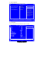
3.1 Entering Setup
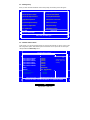
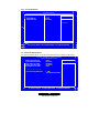
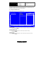
3.2 Standard CMOS Features
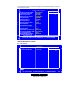
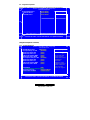
3.3 Advanced BIOS Features
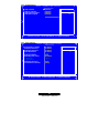
3.4 Advanced Chipset Features
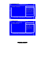
3.5 Integrated Peripherals
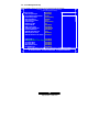
3.6 Power Management Setup
3.7 PnP/PCI Configuration
3.8 PC Health Status
3.9 Frequency and Voltage Control
3.10 Load Fail-Safe Defaults
3.11 Load Optimized Defaults
3.12 Supervisor/User Password Setting
3.13 Exit Selecting
Chapter 4: Diagnostics
4.1 Beep Codes
4.2 Flash Utility
Appendix I: Glossary
Technical Support
……………………………………………..Page 3
……………………………………………..Page 4
……………………………………………..Page 4
……………………………………………..Page 4
……………………………………………..Page 6
……………………………………………..Page 7
……………………………………………..Page 8
……………………………………………..Page 9
……………………………………………..Page 9
……………………………………………..Page 9
……………………………………………Page 10
……………………………………………Page 10
……………………………………………Page 10
……………………………………………Page 11
……………………………………………Page 12
……………………………………………Page 13
……………………………………………Page 14
……………………………………………Page 15
……………………………………………Page 17
……………………………………………Page 18
……………………………………………Page 18
……………………………………………Page 19
……………………………………………Page 19
……………………………………………Page 20
……………………………………………Page 22
……………………………………………Page 22
……………………………………………Page 24
……………………………………………Page 25
……………………………………………Page 27
……………………………………………Page 29
……………………………………………Page 30
……………………………………………Page 30
……………………………………………Page 30
……………………………………………Page 31
……………………………………………Page 31
……………………………………………Page 32
……………………………………………Page 33
……………………………………………Page 34
……………………………………………Page 34
……………………………………………Page 34
……………………………………………Page 35
……………………………………………Page 40

3
http://www.TYAN.com
Before you begin…
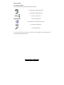
Check the box contents!
The retail motherboard package should contain the following:
1x Tomcat i845GV S2198 motherboard
1x Ultra-DMA-133/100/66 IDE cable
1 x Serial ATA power cable
2 x Serial ATA data cable
1x Tomcat i845GV User’s Manual (Soft Copy)
1x TYAN driver CD (Optional)
1x I/O shield (Optional)
If any of these items are missing, please contact your vendor/dealer for replacement before
continuing with the installation process.

4
http://www.TYAN.com
Chapter 1: Introduction
1.1 – Congratulations!
You have just bought one of the most advanced platforms suited for digital content creation,
productivity and 3D gaming applications. The Tomcat i845GV is based on Intel’s 845GV chipset,
supporting the Intel Pentium 4 or Celeron Processor with 533/400MHz FSB, DDR memory, Intel
Extreme Graphics, and more. These features enable breakthrough performance for today’s rapidly
developing multimedia applications.
Visit TYAN’s Website at http://www.TYAN.com
. There you can find information on all of TYAN’s
products with FAQ’s, distributor’s list and BIOS setting explanations.

5
http://www.TYAN.com
1.2 – Hardware Specifications
Processors
Single Intel® Pentium® 4 , Celeron® ,
Celeron®D processor
One mPGA478 ZIF socket
Onboard VRM 9.0X
533/400 MHz FSB support
Supports Hyper-Threading feature
Expansion Slots
One 32-bit/66 MHz PCI-X 3.3V Slot
One 32-bit/33 MHz PCI 3.3V slot
Chipset
MCH Intel’s 845GV chipset
6300ESB (Hance Rapids) South Bridge chip
ITE IT8712 LPC Super I/O chip
Memory
Two DDR-333*/266/200 DIMM sockets
Up to 2 GB of non-ECC DDR memory
modules
* For 533 MHz FSB only
Integrated Graphics
Intel integrated Extreme Graphics core from
845GV GMCH
Dynamic Video Memory Technology (DVMT)
Integrated PCI IDE (Parallel ATA)
Supports “Native Mode” registers and
interrupts
Independent timing of up to 4 drives, with
separate primary and secondary IDE cable
connections
Supports UDMA 100/66/33 or PIO
IDE/ATAPI devices
Integrated SATA (From 6300ESB)
Two integrated SATA ports up to 1.5 Gbit/s
Supports SATA RAID 0, 1
Integrated LAN Controllers
One 10/100 Fast Ethernet LAN with Intel
82551QM Fast Ethernet NIC (SKU:
S2198GNN- one 10/100 and one GbE)
Shared footprint with optional Intel 82541PI
GbE NIC (SKU: S2198G2N- two GbE NICs)
One 10/100/1000 Gigabit LAN with Intel
82541PI NIC
Two side-by-side RJ45 with LEDs
Integrated I/O
Two 9-pin UART serial support (one via an
optional cable)
One IDE connectors for up to two IDE
devices
Four USB 2.0 ports (3 rear ports, 1 front USB
port via an optional cable)
BIOS
Award BIOS 4 Mb flash ROM (8Mb optional)
Supports APM & ACPI
Auto detection of memory size
Auto configuration of IDE hard disk types
Multiple boot options
Power Management: S1, S3, S4 and S5
Form Factor
Flex ATX (9" x 7.5”)
ATX/12V power connectors (One 20-pin and
one 4-pin)
One USB Type B connector for an external
USB device
Stacked four USB ports (3 usable)
One serial and one VGA ports
Two RJ45 connectors
System Management
H/W monitor functions integrated in IT8712
LPC Super I/O
Total three 3-pin fan headers with
tachometer monitoring and PWM control
Temperature and voltage monitoring
Regulation
FCC Class B (Declaration of Conformity)
European Community CE (Declaration of
Conformity)
Operating System Support
• Windows 2000 and XP
• Windows 98SE and NT4
• Windows ME
• Linux
TYAN reserves the right to add or
discontinue support for any OS with or
without notice.

6
http://www.TYAN.com
Chapter 2: Board Installation
Installation
You are now ready to install your motherboard. The mounting hole pattern of the Tomcat i845GV
matches the FlexATX system board specifications. Your chassis should support a standard
FlexATX motherboard form factor.
How to install our products right…. the first time!
The first thing you should do is read this user’s manual. It contains important information that will
make configuration and setup much easier. Here are some precautions you should take when
installing your motherboard:
(1) Ground yourself properly before removing your motherboard from the antistatic bag.
Unplug the power from your computer power supply and then touch a safely grounded
object to release static charge (i.e. power supply case). For the safest conditions, TYAN
recommends wearing a static safety wrist strap.
(2) Hold the motherboard by its edges and do not touch the bottom of the board, or flex the
board in any way.
(3) Avoid touching the motherboard components, IC chips, connectors, memory modules,
and leads.
(4) Place the motherboard on a grounded antistatic surface or on the antistatic bag that the
board was shipped in.
(5) Inspect the board for damage.
The following pages include details on how to install your motherboard into your chassis, as well
as installing the processor, memory, disk drives and cables.
NOTE DO NOT APPLY POWER TO THE BOARD IF IT HAS BEEN DAMAGED

7
http://www.TYAN.com
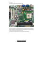
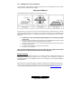
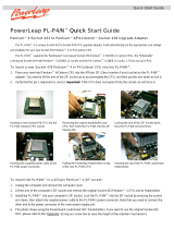
2.1 – Board
The following is an image of the Tomcat i845GV S2198.
The above photograph is purely representative. Due to engineering updates and new board
revisions, certain components may change and or be repositioned. The picture above may
or may not look exactly like the board you received.
The following page includes details on the vital components of this motherboard.

8
http://www.TYAN.com
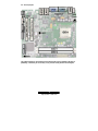
2.2 – Board Jumpers
This jumper diagram is representative of the latest board revision available at the time of
publishing. The board you receive may or may not look exactly like the above diagram.

9
http://www.TYAN.com
2.3 – Fan Connectors (FAN1, FAN2, FAN3)
Use these headers to connect cooling fans, both chassis and
processor fans, to your motherboard. Cooling fans help keep the
system more stable and operating reliably for its product life.
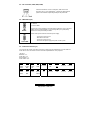
2.4 – CMOS Reset (JP1)
1
3
Default
1
3
Clear CMOS
1,2: Default
2,3: Clear CMOS
Connect pins 1 and 2 together to reset the CMOS settings in case an incorrect
setting causes system instability or you have forgotten your system/setup
password or have just flashed your BIOS.
Power off the system and disconnect the power supply.
- Close pins 2 and 3 on JP1
- Wait about 5 seconds
- Close pins 1 and 2 on JP1
- Reconnect the power supply and power on the system
2.5 – Front Panel Connector (J9)
Your chassis will usually come with connectors to install onto the motherboard, such as HDD and
Power LEDs. The Front Panel Connector has been implemented for such purposes.
J9 Pinout:
HDD LED: 1, 3
Power LED: 2, 4
Reset Switch: 5, 7
Power Switch: 6, 8
Pin 2
Power
LED+
Pin 4
Power
LED-
Pin 6
Power
BT
Pin 8
GND
Pin 10
Reserved
Pin 12
+5V
Pin 14
Key
Pin 16
Reserved
Pin 18
Reserved
Pin 1
HDD
LED+
Pin 3
HDD
LED-
Pin 5
GND
Pin 7
Reset
Switch
Pin 9
+5V
Pin 11
Reserved
Pin 13
GND
Pin 15
Reserved
Pin 17
Reserved

10
http://www.TYAN.com
2.6 – USB TYPE A & B Connectors (JP22, JP21)
USB TYPE A VERTICAL CONNECTOR. CONNECT TO JP21
USB TYPE B CONNECTOR, CONNECT TO JP22
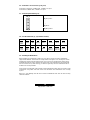
2.7 – External Speaker Header (J15)
Pin_1: Speaker -
Pin_2: NC
Pin_3: NC
Pin_1
Pin_4
Pin_4: Speaker +
2.8 – Port 80 LED Header (J2, Tyan P2198 is needed)
Pin 2
3.3V
Power
Pin 4
LED-A
Pin 6
GND
Pin 8
LED-B
Pin 10
LED-C
Pin 12
LED-D
Pin 14
LED-E
Pin 16
LED-F
Pin 1
SMB
CLK
Pin 3
SMB
Data
Pin 5
LED-H
Pin 7
GND
Pin 9
LED-L
Pin 11
Super IO
GPIO 27
Pin 13
Super IO
GPIO 26
Pin 15
LED-G
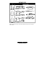
2.9 – Mounting the Motherboard
Before installing your motherboard, make sure your chassis has the necessary motherboard
support studs installed. These studs are usually metal and are gold in color. Usually, the chassis
manufacturer will pre-install the support studs. If you’re unsure of stud placement, simply lay the
motherboard inside the chassis and align the screw holes of the motherboard to the studs inside
the case. If there are any studs missing, you will know right away since the motherboard will not
be able to be securely installed.
Some chassis’ include plastic studs instead of metal. Although the plastic studs are usable, TYAN
recommends using metal studs with screws that will fasten the motherboard more securely
in place.
Below is a chart detailing what the most common motherboard studs look like and how they
should be installed.

11
http://www.TYAN.com
TIP: Use metal studs if possible, as they hold the motherboard into place more securely than
plastic standoffs.

12
http://www.TYAN.com
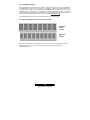
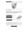
2.10 – Installing the Memory
Before attempting to install any memory, make sure that the memory you have is compatible with
the motherboard as well as the processor. For example, while PC1600 DDR modules are
compatible with all DDR based motherboards, they will not work if you are required to run the
motherboard and processor buses at 133MHz. For this, PC2100 DDR modules are required.
Critically important is whether you’re using the recommended memory for the current board you
have. For this information, please check TYAN’s web site at: www.TYAN.com
.
The following diagram shows the types of RAM modules you may encounter.
Use only 184-pin unbuffered non-ECC memory for S2198.
Unbuffered
Non-ECC
= 8 Chips
Unbuffered
ECC
= 9 Chips
Note: The Tomcat i845GV has two DIMM sockets, which supports a maximum of four banks of
DDR memory (only supports 64 Mb, 128 Mb, 256 Mb, and 512 Mb technologies for
x8 and x16 devices.)

13
http://www.TYAN.com
2.11 – Memory Installation Procedure
When you install the memory modules, make sure the module aligns properly with the memory
slot. The modules are keyed to ensure that it is inserted only one way. The method of installing
memory modules are detailed by the following diagrams.
Once the memory modules are firmly seated in the slot, two latches on either side will close and
secure the module into the slot. Sometimes you may need to close the latches yourself.
To remove the memory module, simply push the latches outwards until the memory module pops
up. Then simply remove the module.
NOTE
Due to the PCI v2.2 specifications, you MUST unplug the power connector to the
motherboard before performing system hardware changes to avoid having your
motherboard boot-up automatically.

14
http://www.TYAN.com
2.12 – Installing the Processor and Heatsink
Your brand new Tomcat i845GV supports the latest processor technologies from Intel. Check
TYAN’s website for latest processor support:
http://www.TYAN.com
The following diagrams will detail how to install your processor:
The processor you choose to use may not look exactly like the one pictured above, nor will the
socket look exactly the same. For example, your processor may appear to be in a different color
and have different markings on it. The diagram is provided as a visual guide to help you install the
processor.
1. Lift the lever on the socket until it is approximately 90
o
or as far back as possible
to the socket.
2. Align the processor with the socket. There are keys underneath the processor just like
on memory modules to ensure that they insert the correct way.
3. Seat the processor firmly into the socket by gently pressing down until the processor
sits flush with the socket.
4. Place the socket lever back down until it snaps into place.
5. Your processor is installed.
Take care when installing Pentium 4 processors as they have very fragile connector pins
below the processor and can bend and break if inserted improperly.
Heatsink Installation
After you are done installing the processor, you should proceed to installing the heatsink. The
heatsink will ensure that the processor does not overheat, and will continue to operate at
maximum performance. An overheated processor is also dangerous to the long-term reliability of
the motherboard.
Because there are many different types of heatsinks available from many different manufacturers,
many have their own method of installation. For the safest method of installation and information
on choosing the appropriate heatsink, please refer to TYAN’s website: http://www.TYAN.com
.

15
http://www.TYAN.com
Finishing Installing the Heatsink
After you finish installing the heatsink onto the processor and socket, attach the end wire of the
fan (which should already be attached to the heatsink) to the motherboard. The following diagram
illustrates how to connect fans onto the motherboard.
After you’re finished installing all the fans you can connect your drives (hard drives, CD-ROM
drives, etc.) to your motherboard.
2.13 – Attaching Drive Cables
Attaching IDE cables to your drives is simple because they only go in one way. TYAN
motherboards have two on-board IDE channels for you to use, each supporting two drives. There
is a white and a black IDE connector on your motherboard. The black connector is the Primary
IDE channel and the white connector is the Secondary IDE channel.
Attaching IDE cables to the IDE connectors is illustrated below:
Simply plug in the BLUE END of the IDE cable into the motherboard IDE connector, and the other
ends into the drive(s). Each standard IDE cable has three connectors, two being close to each
other. The BLUE connector that is far on its own is the end that plugs into the motherboard
whereas the other two connectors are used to connect to drives.
TIP: Pin 1 on the IDE cable (usually denoted by a colored wire) faces the drive’s power
connector.

16
http://www.TYAN.com
Serial ATA
Attaching Serial ATA cables to the Serial ATA connectors are illustrated below:
Plug in one end of the Serial ATA cable into the motherboard Serial ATA connector,
and the other end into the drive. Each standard Serial ATA cable has two
connectors, one at each end. Connectors are the same on both ends.
NOTE
Before continuing onto Connecting External Devices, make sure everything is
properly connected. Things like jumpers and case wiring are the most common
causes of troubleshooting frustrations, both for the end-user and for any
company doing technical support.

17
http://www.TYAN.com
2.14 –
Installing Add-In Cards
Before installing add-in cards, it’s good to be aware if they’re fully compatible with your
motherboard. For this reason, we’ve provided a chart, listing the most common slots that may
appear on your motherboard. Not all the slots in this diagram will be on the same board though,
but there will be combinations. See below for the way the slots look and what each one means.
Simply find the appropriate slot for your expansion card and insert the card in firmly. Do not force
any expansion cards (or anything else) into any slots if they refuse to go in. It’s better to try
another slot or return the faulty card rather than damaging both the motherboard and the card.
TIP: It’s good practice to spread out cards as far apart from each other as possible if you can. This
gives more breathing room and sensitive electronics will cool better and perform more reliably.
NOTE
YOU MUST unplug the power connector to the motherboard before performing
system hardware changes, to avoid having your motherboard boot-up
automatically, due to the PCI v2.2 spec.

18
http://www.TYAN.com
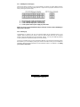
2.15 – Connecting External Devices
The standard devices you should expect to plug into the motherboard are keyboards, mice, and
printer cables. The following diagram will detail the ATX port stack for the following board:
S2198 Tomcat i845GV
TIP: While the ports have been created to accept connectors in only one direction, make sure to
be careful when inserting connectors. At times, attaching connectors in the incorrect orientation
can damage, bend and or break the pins.
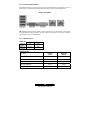
2.16 – LAN LED Scheme
10/100 LAN
Link LED Activity LED
Linked at
10Mbps
Off
Blink
Linked at
100Mbps
Yellow Blink
10/100/1000 LAN
Description
Left LED
(Link)
Right LED
(Activity)
No Link OFF OFF
Linked at 10 Mbps Green OFF
Linked at 100 Mbps Green Green
Linked at 1000 Mbps Green Yellow
Activity at any speed Blink Green

19
http://www.TYAN.com
2.17 – Installing the Power Supply
There are two power connectors on your Tomcat i845GV. By default, the Tomcat i845GV requires
that you have an ATX12V power supply that has a 20-pin and a 4-pin power connector. Do not
use any other type of power supply.
1. Disconnect power supply from electrical outlet
2. Connect ATX12V 4-pin power connector(J11)
3. Connect ATX12V 20-pin power connector(J18)
4. Connect power cable to power supply to power outlet
Make sure you have connected BOTH the 20-pin and 4-pin connectors before attempting to
apply power to the board.
2.18 – Finishing Up
Congratulations on making it this far! You’re finished setting up the hardware aspect of your
computer. Before closing up your chassis, make sure that all cables and wires are connected
properly, especially IDE cables and most importantly, jumpers. You may have difficulty powering
on your system if the motherboard jumpers are not set correctly.
In the rare circumstance that you have experienced difficulty, even though the instructions herein
were followed, you can find help by asking your vendor for assistance. If they are not available for
assistance, please find setup information and documentation online at our website or by calling
your vendor’s support line.

20
http://www.TYAN.com
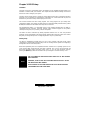
Chapter 3: BIOS Setup
Installation
The BIOS is the basic input/output system, the firmware on the motherboard that enables your
hardware to interface with your software. This chapter describes different settings for the BIOS
that can be used to configure your system.
The BIOS section of this manual is subject to change without notice and is provided for reference
purposes only. The settings and configurations of the BIOS are current at the time of print, and
therefore may not match exactly what is displayed on screen.
This section describes the BIOS setup program. The setup program lets you modify basic
configuration settings. The settings are then stored in a dedicated, battery-backed memory (called
NVRAM) that retains the information when the power is turned off.
This motherboard’s BIOS is a customized version of the industry-standard BIOS for IBM PC
compatible personal computers. The BIOS provides critical, low-level support for the system’s
central processing unit (CPU), memory, and I/O subsystems.
This BIOS has been customized by adding important features such as virus and password
protection, power management, and chipset “tuning” features that control the system. This section
will guide you through the process of configuring the BIOS for your system setup.
Starting Setup
The BIOS is immediately activated when you turn on the computer. The BIOS reads system
configuration in CMOS RAM and begins the process of checking out the system and configuring it
through the Power-On-Self-Test (POST).
When these preliminary tests are completed, the BIOS searches for an operating system on one
of the system’s data storage devices (hard drive, CD-ROM, etc). If one is found, the BIOS will
launch that operating system and hand control over to it. You can enter the BIOS setup by
pressing the [Delete] key when the machine boots up and begins to show the memory count.
NOTE
THE FOLLOWING SECTION DETAILS MOST IF NOT ALL OF THIS BOARD’S
BIOS FEATURES.
HOWEVER, YOUR ACTUAL BIOS SETUP MAY NOT BE EXACTLY AS THE
ONE DETAILED IN THIS MANUAL.
PLEASE REFER TO THE TYAN WEBSITE FOR UP TO DATE FEATURES
CONCERNING BIOS AND OTHER DATA.
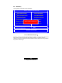
Page is loading ...
Page is loading ...
Page is loading ...
Page is loading ...
Page is loading ...
Page is loading ...
Page is loading ...
Page is loading ...
Page is loading ...
Page is loading ...
Page is loading ...
Page is loading ...
Page is loading ...
Page is loading ...
Page is loading ...
Page is loading ...
Page is loading ...
Page is loading ...
Page is loading ...
Page is loading ...
Page is loading ...
-
 1
1
-
 2
2
-
 3
3
-
 4
4
-
 5
5
-
 6
6
-
 7
7
-
 8
8
-
 9
9
-
 10
10
-
 11
11
-
 12
12
-
 13
13
-
 14
14
-
 15
15
-
 16
16
-
 17
17
-
 18
18
-
 19
19
-
 20
20
-
 21
21
-
 22
22
-
 23
23
-
 24
24
-
 25
25
-
 26
26
-
 27
27
-
 28
28
-
 29
29
-
 30
30
-
 31
31
-
 32
32
-
 33
33
-
 34
34
-
 35
35
-
 36
36
-
 37
37
-
 38
38
-
 39
39
-
 40
40
-
 41
41


Tyan Tomcat i845GV S2198 User manual
- Type
- User manual
- This manual is also suitable for
Ask a question and I''ll find the answer in the document
Finding information in a document is now easier with AI
Related papers
Other documents
-
DFI NB78-BL User manual
-
Lenovo 6300 User manual
-
DeLOCK 70098 Datasheet
-
BESTEK MEB-7400D User manual
-
MATSONIC BC875PLG User manual
-
VTech ATI A3 + ALI M1535D+ Technical Reference Booklet
-
VIA Technologies VX800 Series Technical Manual
-
 Powerleap PL-P4 Quick start guide
-
Intel 945GME User manual
-
