Page is loading ...

REVISION A
Form No. 3103784.033 10/16
(French 3108200.027_A)
©2016 Dometic Corporation
LaGrange, IN 46761
OPTIMA
TENSION
RAFTER
INSTALLATION & OPERATING
INSTRUCTIONS
• Optima Tension Rafter/Cradle Support;
• Optima Center Support;
• Optima Tension Rafter/Cradle Support with
USA
SERVICE OFFICE
Dometic Corporation
1120 North Main Street
Elkhart, IN 46514
CANADA
Dometic Corporation
46 Zatonski, Unit 3
Brantford, ON N3T 5L8
CANADA
SERVICE CENTER &
DEALER LOCATIONS
Please Visit:
www.eDometic.com
Center Support Combo
This manual must be read and
understood before installation, ad-
justment, service, or maintenance
is performed. This unit must be
installed by a qualied service tech-
nician. Modication of this product
can be extremely hazardous and
could result in personal injury or
property damage.
Lire et comprendre ce manuel avant
de procéder à l'installation, à des
réglages, de l'entretien ou des répa-
rations. L'installation de cet appareil
doit être effectuée par un réparateur
qualié. Toute modication de cet
appareil peut être extrêmement dan-
gereuse et entraîner des blessures ou
dommages matériels.

OPTIMA TENSION RAFTER/
CRADLE SUPPORT/CENTER SUPPORT
2
SAFETY INSTRUCTIONS
This manual has safety information and instruc-
tions to help users eliminate or reduce the risk of
accidents and injuries.
RECOGNIZE SAFETY INFORMATION
This is the safety-alert symbol. When you see
this symbol in this manual, be alert to the poten-
tial for personal injury.
Follow recommended precautions and safe op-
erating instructions.
UNDERSTAND SIGNAL WORDS
A signal word , WARNING OR CAUTION is used
with the safety-alert symbol. They give the level
of risk for potential injury.
indicates a potentially hazard-
ous situation which, if not avoided, could result
in death or serious injury.
indicates a potentially hazard-
ous situation which, if not avoided, may result in
minor or moderate injury.
used without the safety alert
symbol indicates, a potentially hazardous situa-
tion which, if not avoided, may result in property
damage.
Read and follow all safety information and in-
structions.
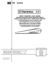
FIG. 1
Black
Adjustment
Knob
Tension Rafter
OPTIMA TENSION
RAFTER SYSTEM
INSTALLATION/OPERATION
For Installation of: Optima Tension
Rafter/Cradle Support; Optima Center Support
and Optima Tension Rafter/Cradle Support
with Center Support Combo
APPLICATION:
The Optima Tension Rafter System works on any auto-
matic roll-up type awning that uses a roller tube. It is avail-
able as a complete system including self-adjusting Ten-
sion Rafter, Center Support and Storage Cradle in one
attractive package; or separately as a Center Support or
Tension Rafter/Cradle Support.
IMPORTANT: Read and understand the entire installa-
tion procedure before starting installation.
NOTE: Dometic Corporation assumes no liability for dam-
ages or injuries resulting from installation or operation of
this product.
Dometic Corporation reserves the right to modify appear-
ances and specications without notice.
INSTALLATION OF TENSION RAFTER
Tools required:
• Measuring Tape • Ladder
• Electric Drill • Pencil
• Drill Bits: #7 or 3/16"; 5/16" • Wrench or Socket: 7/16"
• Center Punch • Pop Rivet Gun (Neces-
sary only if Backing Plate is
needed)
• Phillips Screwdriver
• Silicone Sealant
1. Install Black Adjustment Knob on left side of ten-
sion rafter. (See FIG. 1).

OPTIMA TENSION RAFTER/
CRADLE SUPPORT/CENTER SUPPORT
3
Top
Bracket
Pad Assembly
NOTE: It may be necessary to slightly extend the tension
rafter further to obtain the right angle shown in FIG. 3.
IMPORTANT: Tension rafter, top cradle, top bracket,
and vehicle MUST form right angles as shown in FIG.
3 for tension rafter to operate correctly.
FIG. 4
FIG. 5
FIG. 3
G. Once right angles are established, mark location
of mounting holes in top bracket on vehicle.
H. Detach top bracket/pad assembly from tension
rafter by removing the 1/4-20 x 2-1/2" hex head
bolt and 1/4-20 lock nut.
3. A. Position top bracket/pad assembly against
vehicle and predrill with #7 or 3/16" drill bit.
B. Secure using three (3) #14 x 1-1/2" pan head
screws provided with a small dab of silicone seal-
ant on each screw. (See FIG. 4)
NOTE: Be sure to use a dab of silicone sealant on every
screw or rivet where a hole has been drilled in the side of
the vehicle. This will prevent possible water leakage.
4. USE OF BACKING SUPPORT PLATE (FIG. 5)
For installations where there is not sufcient sup-
port for mounting the top bracket, install the supplied
backing support plate as follows:
A. Using the support plate as a template, mark and
drill four (4) 3/16" dia. holes through the vehicle
side.
2. A. Attach the tension rafter to the top bracket/pad
assembly with the 1/4-20 x 2-1/2" hex head bolt
and 1/4-20 lock nut with nylon insert provided.
(See FIG. 2A)
FIG. 2B
FIG. 2A
B. With awning closed, position the tension rafter at
the center of the awning so that it has a minimum
of 69" of unobstructed clearance below the aw-
ning rail. If windows and/or service accesses in-
terfere, relocate tension rafter as close to center
of awning as the situation will allow. (See FIG.
2B).
C. While holding tension rafter vertically at mounting
location, carefully set roller bracket end of tension
rafter on ground and loosen black adjustment
knob on side of tension rafter.
D. With tension rafter still resting on ground, extend
the tension rafter up so that the top of the tension
rafter almost touches the bottom of the closed
awning.
E. Lock black adjustment knob on side of awning.
F. Carefully climb ladder. With tension rafter still
resting on the ground, position the top bracket/
pad assembly against the vehicle so that the top
cradle of the tension rafter touches the bottom of
the closed awning as shown in FIG. 3.
1/4" X 2-1/2"
Hex Head Bolt
Pad
Tension Rafter
Top Bracket
1/4-20 Lock Nut
With Nylon Insert
Top Cradle
Awning Length
Equal
Equal
Awning
Optima
Tension Rafter
NOTE: When installing two tension rafters, divide awning
length into three equal parts.
Awning
Rail
#14 X 1-1/2"
Phillips
Pan Head
Screws
3/16" DIA.
Oscar
Rivets
Backing
Support
Plate
IMPORTANT: For
Tension Rafter to
operate correctly,
bracket, cradle
and rafter must be
mounted at right
angles as shown.
PAD
Top
Bracket
Vehicle
Bottom
Of Closed
Awning
90°
Right
Angle
90°
Right
Angle
Tension Rafter

OPTIMA TENSION RAFTER/
CRADLE SUPPORT/CENTER SUPPORT
4
NOTE: When installing the tension rafter on a curved
vehicle which does not allow for rafter storage, bottom
bracket installation is not required.
FIG. 7
FIG. 6D
7. FOR USE ON AWNINGS WITH VALANCE THAT
HANGS FROM FRONT OR BOTTOM OF ROLLER
TUBE. (SEE FIG. 7)
Note: If valance hangs behind roller tube, opposite of that
shown in gure 7 then awning is over or under extended.
Adjust valance position to front or bottom of roller tube so
that the fabric is taut.
A. Extend the awning to the fully open position, dis-
connect tension rafter from bottom bracket and
swing it up into position making sure the rafter is
perpendicular to the roller tube.
B. Mark the spot on the roller tube where the dowel
of the roller bracket is to be inserted 1-1/4" below
the fabric. (See FIG. 7)
C. To prevent damaging the fabric, rst center-
punch the dowel hole or pilot drill, using a small
drill bit.
D. Use a 5/16" dia. bit to drill dowel hole into roller
tube.
8. TO TENSION FABRIC: See Operating Instruction
Section TO TENSION FABRIC beginning with Step
4.
9. TO STORE AWNING: See Operating Instruction
Section TO CLOSE beginning with Step 17.
Top Bracket Pad Assembly
Push-In Panel
Fasteners
Tension Rafter
Awning Fabric
Dowel
Tension Rafter
Roller Bracket
Roller Tube
Valance
FIG. 6A
B. Secure the plate using the 3/16" dia. oscar rivets
provided. Plate should be pushed up and touch
rail. (See FIG. 5)
C. Proceed with installation by installing the top
bracket of the tension rafter directly onto the
backing support plate.
5. Reattach the tension rafter to the top bracket with
the 1/4-20 x 2-1/2" hex head bolt and 1/4-20 lock nut
with nylon insert provided. (See FIG. 2A)
6. A. Attach the bottom bracket to the roller bracket
using the ball lock pin. (See FIG. 6A)
B. Position the bottom bracket over the oor line, or
solid structural member, 69" or more below the
awning rail.
FIG. 6B
FIG. 6C
IMPORTANT: The bottom bracket MUST be mounted
to the oorline or solid structural member. If these are
not available, the vehicle shell must be adequately
reinforced.
C. With the tension rafter hanging straight down
from the top bracket, mark the bottom bracket
screw placements.
D. Detach bottom bracket and predrill two (2) #7 or
3/16" dia. holes.
E. Secure bottom bracket with two (2) #14 or 1-1/2"
pan head screws with a small dab of silicone
sealant on each screw. (See FIG. 6B)
F. Attach tension rafter to bottom bracket using ball
lock pin. (See FIG. 6C).
G. Attach pad to tension rafter with the supplied
push-in panel fasteners. (See FIG. 6D)
Roller
Bracket
Bottom Bracket
Ball
Lock
Pin
Bottom
Bracket
#14 X 1-1/2" Phillips
Pan Head Screws
Tension
Rafter
Bottom
Bracket
Ball
Lock
Pin

OPTIMA TENSION RAFTER/
CRADLE SUPPORT/CENTER SUPPORT
5
FIG. 1A
FIG. 1B
2. Remove the ball lock pin while grasping the bot-
tom section of the tension rafter. Detach the tension
rafter and replace pin in bottom bracket. (FIG. 2)
FIG. 2
DO NOT attempt to close awning until ten-
sion rafter is in the correct storage posi-
tion described in Operating Instructions TO
CLOSE Step 17, or damage to the awning
may occur.
OPERATING OF TENSION RAFTER
TO TENSION FABRIC
1. A. From awning travel position, release pressure
on Optima Tension Rafter by sliding lock on lift/
tension mechanism lever up and pulling lever
forward. Roller should be as high up as you can
reach as the roller and rafter pivot at different
locations. (FIGS. 1A & 1B)
B. Roll out awning per awning Operating Instruc-
tions.
C. Raise awning roller tube to eye level or a position
that is comfortable to reach.
3. While raising the tension rafter toward the awning
roller tube, loosen the adjusting knob on the left side
of the tension rafter. (FIG. 3)
FIG. 3
4. Extend tension rafter and attach it to awning roller
tube by inserting dowel at end of rafter into drilled
hole in roller tube. (FIG. 4)
FIG. 4
FIG. 5A
FIG. 5B
5. Slide lock tension mechanism up and pull lever
down while holding dowel pin at end of rafter in roller
tube. (FIGS. 5A & 5B)
Tension Rafter
Lift
Mechanism
Lever
Lift/
Mecha-
nism
Lever
Lift/
Mecha-
nism
Lever
Tension
Rafter
Bottom
Section
Of Tension
Rafter
Bottom
Bracket
Ball
Lock
Pin
Adjustment
Knob
Tension
Rafter
Awning
Roller Tube
Hole In
Roller
Tube
Dowel Pin
Tension Rafter
Tension
Mechanism
Lever
Tension
Mechanism
Lever Lock
Roller
Tube
Roller Tube
Tension
Mechanism
Lever

OPTIMA TENSION RAFTER/
CRADLE SUPPORT/CENTER SUPPORT
6
FIG. 8
FIG. 9
FIG. 7C
FIG. 7D
FIG. 7B
B. Slide the knob toward the vehicle and carefully
swing the center support down placing the foot of the
center support on the ground. (FIGS. 7B, 7C & 7D)
8. The awning can now be raised to a higher posi-
tion with no further adjustment to the tension rafter
required. If the awning is to be placed into patio
position, release the roller tube lock lever before
detaching and rotating the awning arms out. This will
allow the rafter roller bracket to continue to t snugly
against the roller tube.
9. When the awning is set in desired position, raise
the center support to hold the roller tube at desired
height and secure by rmly tightening the adjust-
ment knob. (FIG. 8)
DO NOT extend center support so that less
than 3" of the secondary arm remains in the
main arm. (FIG. 8)
10. Anchor the foot of the center support by driving the
two (2) metal spikes provided into the ground. (FIG.
9)
Tension
Rafter
Center
Support
Center
Support
Center
Support Foot
Center
Support
Adjustment
Knob
Secondary Arm (Do
Not Extend So Less
Than 3" Remain)
Spike
Foot
Spike
FIG. 6A
FIG. 6B
7. A. If center support is to be used, release it from
the tension rafter at this time by loosening the larger
1-7/8" dia. adjustment knob. (FIG. 7A)
FIG. 6C
6. A. Firmly tighten adjustment knob on side of ten-
sion rafter. (FIG. 6A)
B. Grasping the tension mechanism lever, care-
fully move it up even with the tension rafter and
slide the lock over the lever to secure the rafter.
(FIG. 6B)This step pushes the roller tube out and
stretches the fabric taut. The tension rafter is de-
signed to use the full stroke of the tension mecha-
nism for 25 foot awnings. Shorter awnings may
require less tension.
The amount of tension may be lessened by start-
ing with the lever positioned at less of an angle
prior to tightening the knob. (FIG. 6C)
FIG. 7A
TENSION AFTER
ROLLER TUBE
1-7/8" DIA.
ADJUSTMENT KNOB
CENTER
SUPPORT
Lift/Tension
Mechanism
Lever
Reduced
Stroke For
Less Tension
Full Stroke
For Maximum
Tension
Adjustment
Knob

OPTIMA TENSION RAFTER/
CRADLE SUPPORT/CENTER SUPPORT
7
FIG. 10
FIG. 11
TO CLOSE:
When used on curved vehicle that does not
allow for permanent installation, the tension
rafter MUST be removed from the side of ve-
hicle before traveling.
11. Remove spikes from center support foot and loosen
adjustment knob. (FIGS. 10 & 11)
FIG. 12
12. Lower the awning. If roller tube lock lever was released,
be sure to return to ROLL DOWN POSITION so that
the awning will not snap back against the coach when
awning rafter arms are released.
13. Swing the center support up to the tension rafter and
slide the dowel pin that the center support foot pivots
on, into the opening of the channel tracks at the end of
the inner rafter. (FIG. 12)
Make sure the pin is seated inside the channel tracks
of the tension rafter before securely tightening the larger
1-7/8" adjustment knob.
FIG. 14
FIG. 13
If the 3/16" dia. dowel pin of the center sup-
port foot is not seated inside the channel
tracks of the tension rafter, the center sup-
port may fall during tension rafter operation
and result in possible injury.
14. Relieve tension of the tension rafter by unlocking
and carefully pulling the tension mechanism lever
down. (FIG. 13)
FIG. 14A
FIG. 14B
FIG. 14C
15. Loosen adjustment knob on side of tension rafter
and push tension mechanism lock up, slide tension
mechanism lever down. (FIGS. 14A, 14B & 14C)
16. Remove tension rafter from roller tube and attach to
bottom bracket on side of vehicle with ball lock pin.
(FIG. 15)
17. A. Slide tension mechanism lock up to unlock lever
and pull lever forward. (FIG. 16)
B. Close awning per awning Operation Instructions.
18. Tighten knob on side of tension rafter and push ten-
sion mechanism lever back. This will lift the awning.
The amount of lift may be lessened by starting with
the lever positioned at less of an angle before tight-
ening the adjustment knob.
Spike
Spike
Foot
Center
Support
Adjustment
knob
Center
Support
Tension
Rafter
Dowel
Pin
Openings Of Channel
Tracks Of Tension Rafter
Center
Support
Foot
Adjustment
Knob
Tension
Mechanism
Lever
Tension
Mechanism
Lever Lock
Tension
Mechanism
Lever
Tension
Mechanism
Lever Lock
Tension
Mechanism
Lever

OPTIMA TENSION RAFTER/
CRADLE SUPPORT/CENTER SUPPORT
8
FIG. 1
NOTE: If the Optima Center Support is being used in con-
junction with the Optima Tension Rafter, the roller bracket
is not required and the center support should be attached
to the tension rafter as pictured in FIG. 2. To attach center
support, use 1/4-20 nut and 1/4-20 x 2-1/2" hex head bolt
in the tension rafter. Install the center support with the two
rubber sleeves (provided) on both sides of the center sup-
port. (FIG. 2)
INSTALLATION OF
CENTER\ SUPPORT
APPLICATION:
The Optima Center Support can be used on any auto-
matic roll-up type awning that uses a roller tube. It may be
purchased separately and used by itself as a center sup-
port or added to the Optima Tension Rafter/Cradle Sup-
port or purchased in the complete Optima Tension Rafter
System combination.
IMPORTANT: Read and understand the entire installa-
tion procedure before starting installation.
NOTE: Dometic Corporation assumes no liability for dam-
ages or injuries resulting from installation or operation of
this product.
Dometic Corporation reserves the right to modify appear-
ances and specications without notice.
Tools required:
• Measuring Tape • Center Punch
• Pencil • 7/16" Wrench or Socket
• Electric Drill • Hammer
• 1/4" Drill Bit
1. Assemble the center support by installing the roller
bracket assembly onto the main arm with a 1/4-20 x
1-3/4" hex head bolt and lock nut with nylon insert.
(FIG. 1)
1/4-20 X 1-3/4"
Hex Head Bolt
Roller
Bracket
Assembly
Nylon
Lock Nut
Center
Support
FIG. 16
FIG. 17
FIG. 18
FIG. 15
19. Slide lock on lever down to secure mechanism.
Optima Tension Rafter System is now functioning as
a cradle support and is ready for travel. (FIGS. 17 &
18)
Lift
Tension
Mecha-
nism
Lever
Lock
Awning
Optima
Tension
Rafter/
Cradle
Support
Tension
Rafter
Bottom
Bracket
Ball
Lock
Pin

OPTIMA TENSION RAFTER/
CRADLE SUPPORT/CENTER SUPPORT
9
FIG. 2
FIG. 3
2. Set up the awning so that the roller tube is at eye
level.
3. Locate the center of the awning or, if tension rafter is
being used, locate its mounting position.
4. Mark the spot on the bottom center of the roller tube
where the dowel of the roller bracket is to be insert-
ed. (FIG. 3)
5. It is recommended to rst center-punch before drill-
ing a 1/4" dia. hole in the roller tube.
6. The center support is now ready for operation.
FIG. 4
FIG. 5
FIG. 6
FIG. 7
FIG. 8
OPERATION OF CENTER SUPPORT
7. Open the awning and set to desired height (FIG. 4)
8. Insert the dowel pin in the roller bracket into the 1/4"
dia. hole drilled in the roller tube. (FIG. 5)
9. Extend the center support up to hold the roller tube
at desired height and tighten the adjustment knob
rmly. (FIGS. 6 & 7)
DO NOT extend center support so less than
3" of the secondary arm remains in the main
arm of the center support. (FIG. 7)
10. Anchor the foot of the center support by driving the two
metal spikes (provided) into the ground. (FIG. 8)
Awning Fabric
Center
Support
Dowel
Pin
Awning
Center Support
Adjusting
Knob
Foot
Center
Support
Adjusting
Knob
Adjusting
Knob
Spike
Spike
Foot
Roller Tube
Awning Fabric
Center
Support
Dowel
Pin
Tension
Rafter
Rubber Sleeve
Rubber Sleeve
1/4-20 X 2-1/2"
Hex Head Bolt
Nylon
Lock Nut
Center Support
/