Page is loading ...

VER 1.0
A
R
-B1740
FORM FACTOR
Half-sieze
SBC
PCI
CPU TYPE
mPG
A
478M
CPU
Pentium M
1.7GHz
CHIPSET MEMORY I
/
O
ICH4
Intel 855GME
DDR
1GB
USB/Serial
/
IrDA
/
LPT
LAN
10/100/Gigabit
Mb
p
s
A
UDIO
A
C'97
IDE x 4
FDD x 2
USER'S MANUAL

Copyright
©
2003
All Ri
g
hts Reserved.
W
arnin
g
The information in this document is subject to change without prior notice in order to improve
the reliability, design and function. It does not represent a commitment on the part of the
manufacturer.
Under no circumstances will the manufacturer be liable for any direct, indirect, special,
incidental, or consequen-tial damages arising from the use or inability to use the product or
documentation, even if advised of the possibility of such damages.
This document contains proprietary information protected by copyright. All rights are reserved.
No part of this manual may be reproduced by any mechanical, electronic, or other means in
any form without prior written permission of the manufacturer.
Single Board Computers and their components contain very delicate Integrated
Circuits (IC). To protect the Single Board Computer and its components against
damage from static electricity, you should always follow the following precautions
when handling it :
1. Disconnect your Single Board Computer from the power source when you want to wor
k
on the inside
2. Hold the board by the edges and try not to touch the IC chips, leads or circuitry
3. Use a grounded wrist strap when handling computer components.
4. Place components on a grounded antistatic pad or on the bag that came with the Single
Board Computer, whenever components are separated from the system
5. Compact Flash Card is not hot-plug since it uses IDE interface.
About this M
a
nual
This manual provides general information and installation instructions about the board and this
User's Manual is intended for experienced users and integrators with hardware knowledge of
personal computers. If you are not sure about any description in this User's Manual, please
consult your vendor before further handling.
Replacing the lithium batte
r
y
Incorrect replacement of the lithium battery may lead to a risk of explosion.
The lithium battery must be replaced with an identical battery or a battery type recommended
by teh manufacturer (BR2335).
Do not throw lithium batteries into the trashcan. It must be disposed of in accordance with
local requlations concerning special waste.
A
R
-
B1740 User'
s
Manua
l
2

W
arranty
This product is warranted to be in good working order for a period of one year from the date
of purchase. Should this product fail to be in good working order at any time during this period
,
we will, at our option, replace or repair it at no additional charge except as set forth in the
following terms. This warranty does not apply to products damaged by misuse, modifica-
tions, accident or disaster.
PACKING LIST
A
R-B1740
Vendor assumes no liability for any damages, lost profits, lost savings or any other incidental
or consequential damage resulting from the use, misuse of, or inability to use this product.
Vendor will not be liable for any claim made by any other related party.
Vendors disclaim all other warranties, either expressed or implied, including but not limited to
implied warranties of merchantibility and fitness for a particular purpose, with respect to the
hardware, the accompanying product's manual(s) and written materials, and any accompany-
ing hardware. This limited warranty gives you specific legal rights.
Return authorization must be obtained from the vendor before returned merchandise will be
accepted. Authorization can be obtained by calling or faxing the vendor and requesting a
Return Merchandise Authorization (RMA) number. Returned goods should always be accompa-
nied by a clear problem description.
1
x
P
R
IN
T
Cable
2xCOM Flat Cable
1xFDD Cable
1xUSB V2.0 Cable
1xAUDIO Cable
1xIDE Cable
1xUltraDMA 100 IDE Flat Cable
1xY Cable
1
x
Cooler
1
x
CD-
R
OM
(
dri
v
er
)
Before u
p
and runnin
g
,
p
leasemakesurethe
p
acka
g
e contains all of above accessories.
If an
y
of the above items is dama
g
ed o
r
missin
g
, contact
y
ou
r
vendo
r
immediatel
y
.
Ordering Codes
AR-B1740
Low power Intel Pentium-M Half size PCI BUS SBC with CRT/LCD & LAN
A
R
-
B1740 User'
s
Manua
l
3

A
R
-
B1740 User'
s
Manua
l
4
Specification
MODEL AR-B1740
System
Board
SYSTEM AR-B1740
CPU mPGA478M socket support: Pentium-M with FSB 400 up to 2.0 GHz
CPU Cache CPU Integrated
Chipset Southbridge: ICH4; Northbridge: Intel 855GME
Memory One 184-pin DIMM sockets support up to 1GB DDR SDRAM (266MHz/333MHz) ECC
Display
Chipset: 855GME integrated graphic, 4 x AGP
Display Memory: Memory shared up to 64MB (DVMT)
Display Type: CRT/ LCD
LVDS panel supported 2 channel 48 bit resolution up to 1600x1200 at 85Hz & 2048x1536 at 75Hz
TTL 24 bit supported
Fast Ethernet 1x Onboard 10/100 Mbps Fast Ethernet (Intel 82562ET PHY)
Audio
ICH4 integrated audio with AC97 Codec
Audio Interactive (MIC in, Line-in, Speaker out, AC'97 ver. 2.3)
Flash Disk CompactFlash Type II
Multiple I/O
Serial Port 1 x RS-232C & 1 x RS-232C/422/485
Parallel Port 1 x Parallel prot supports SPP, EPP and ECP mode
Enhanced IDE 2 ports and up to 4 ATAPI devices, Ultra DMA transfer rates 33/66/100MB/sec (IDE1: 40 Pin DMA 100; IDE2: 44 Pin DMA 33)
Floppy 2 floppy disk drives
IrDA 1 x IrDA
USB 6 x USB 2.0 Ports
K/B & Mouse 1 x PS/2 connector for keyboard & mouse
Watchdog Timer 256 level generates RESET
Mechanical and Environment
Power Requirement: +5V@4.25A, +[email protected] (Pentium M 1.7Ghz + 1GB DDR SDRAM)
Power Consumption: TBD
Typical: 18W@5V (1.1GHz LV CPU)
Operating Temperature: 0 ~ 60¢XC (32 ~ 140¢XF)
Storage Temperature: -20 ~ 80¢XC (-68 ~ 176¢XF)
Relative Humidity: 0% ~ 90%
Dimension (Lx W): 185 x 122 mm (7.3" x 4.8")
Weight: 0.6Kg (1.32 Ib)

5
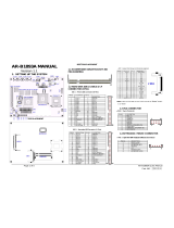
Board Layout Board Dimension
A
R
-
B1740 User'
s
Manua
l
5

A
R
-
B1740 User'
s
Manua
l
6
Jumper/Connector quick reference Jumper/Connector Quick Reference
Jumpers
Lable Function
JBAT1 Clear CMOS
JRS2 COM2 RS-232C / 422 / 485 Selection
JVLCD1 LVDS voltage selection
JSMB1 External SMB
JFRT1 Switches & Indicators
J1 CPU Type selection
Connectors
Lable Function
AUDIO1 Audio Interface Port
CFD1 Compact Flash Disk
COM1 RS-232C Serial Port
COM2 Serial Port (RS-232C/422/485)
CPUF1 CPU Fan connector
DIMM1 DDR bank 1/2 184 pin DIMM Socket
EATX1 ATX feature connector
EKB1 External Keyboard Connector
FDD1 Floppy Disk Drive Connector
IDE1 Primary IDE Connector
IDE2 Secondary IDE Connector
INV1 LCD Inverter Connector
KBM1 Keyboard and PS/2 Mouse
LAN1 10/100 LAN1 Connector
LAN2 10/100/1000 M Connector
LCD1 18bit/24bit TTL Flat Panel Connector (DF13 40 pin)
LVDS1 24bit LVDS Panel Connector (DF13 30 pin)
LPT1 Parallel Port
PWR1 4P Auxiliary Power Connector
IR1 Infrared (IR) Connector
USB1 USB Port 0,1
USB2 USB Port 2,3
USB3 USB Port 4,5
VGA1 VGA Display Connector

CMOS Jumpe
r
Settings
CMOS Operation (JBAT1)
T
yp
e : JBAT1: onboard 3-
p
in heade
r
1
2
3
JB
A
T1
If the AR-B1740 refuses to boot due to inappropriate CMOS settings, here is how to
p
roceed to clea
r
(
reset
)
the CMOS to its default values.
External SMB
T
yp
e : JSMB1: onboard 3-
p
in heade
r
1 2
L
VDS LCD P
owe
r
Selection
T
ype : JVLCD1: onboard 3-pin heade
r
The volta
g
e of LCD
p
anel could be selected b
y
JV9in5Vo
r
3.3V .
1
2
3
JVLCD1
CMOS Setup (JBAT1) JBAT1 Status
Normal Operation 1-2 ON
Clear CMOS 2-3 ON
default setting 1-2 ON
Pin Description
1 SMB DATA
2 SMB CLK
3 GND
Mode JVLCD1
3.3V 2-3
5V 1-2
default setting 3.3V
A
R
-
B1740 User'
s
Manua
l
7

A
R
-
B1740 User'
s
Manua
l
8
Serial Port Selection
(
RS232C/422/485
)
RS-232C/422/485 Mode select (JRS2)
T
ype : JRS2: onboard 6-pin(2*3) heade
r
1
3
5
2
4
6
CPU T
yp
e Selection
T
yp
e : J1: onboard 2-
p
in heade
r
The CPU VccA
(
PLL su
pp
l
y
volta
g
e
)
could be selected b
y
J1 in 1.5 V o
r
1.8
Note: Please make sure the cor
r
ect settin
g
of CPU VccA before u
p
and runnin
g
.
JRS2 Selection 1-2 3-4 5-6
RS-232C ON OFF OFF
RS-422 OFF ON OFF
RS-485 OFF OFF ON
default setting RS-232C
Mode J1
CPU VccA : 1.8V ON
CPU VccA : 1.5V OFF
default setting VccA : 1.8 V
12

Switches and Indicators
Reset Button
Connector : RESET
Pin Description
1 RESET
2 GND
1 2
PLED
RESET
HLED
ATX Soft Power Switch
ESPK
9 10
JFRT1
Power LED Connector
Connector : PLED
Power LED can be indicated when the CPU card is on or off. And keyboard lock can be
used to disable the keyboard function so the PC will not respond by any input.
Pin Description
3 Power LED+
4 Power LED-
Power LED status description
Power Type AT Power ATX Power
Power On On On
Power Suspend Fast Glittering Fast Glittering
Power Off Off Slow Glittering
Hard Disk LED Connector
Connector : HLED
Pin Description
5 Hard Disk LED+
6 Hard Disk LED-
External Speaker Connector
Connector : ESPK1
Pin Description
7 +5V
8 Speak out
A
R
-
B1740 User'
s
Manua
l
9

A
udio Interface
4321
COM Port Connector
COM1
COM2
A
R
-
B1740 User'
s
Manua
l
10
Connector : Audio1
Type : Onboard 10-pin box header
Pin Description Pin Description
1 LINE IN LEFT 2 LINE IN RIGHT
3 GND 4 GND
5 MIC 6 NC
7 GND 8 GND
9 SPEAKER LEFT 10 SPEAKER RIGHT
Connector : COM1
Type : onboard 10-pin box header
Pin Description Pin Description
1 DCD 2 RXD
3 TXD 4 DTR
5 GND 6 DSR
7 RTS 8 CTS
9 RI
2
Audio1
1
9
10
Connector : COM2
Type : onboard 10-pin box header
Pin Description Pin Description
1 DCD2 2 RXD2
3 TXD2 4 DTR2
5 GND 6 DSR2
7 RTS2 8 CTS2
9 RI 10 NC
Connector : JCOM2
Type : onboard 4-pin box header
Pin Description Pin Description
1 485DATA+(422TXD+) 2 485DATA-(422TXD-)
3 422RXD+ 4 422RXD-

A
R
-
B1740 User'
s
Manua
l
11
CPU Fan Connector
123
Connecto
r
: CPUF1
T
yp
e : onboard 3-
p
in wafe
r
connecto
r
C
PU
F
1
Pin Description
1 GND
2 +12V
3
F
ANDectect
Ke
y
boa
r
d & Mouse Connecto
r
EKB1
1
2
3
4
5
1
3
5
6
2
AT Keyboard
Connector : EKB1
Type : Onboard 5-pin header
Pin Description Pin Description
1 CLK 2 DATA
3 NC 4 GND
5 Vcc
PS/2 Keyboard & Mouse
Connector: KBM1
Type: 6-pin Mini DIN connector on bracket
Pin Description Pin Description
1 KB-DATA 2 MS-DATA
3 GND 4 VCC
5 KB-CLK 6 MS-CLK
Note: KBM1 supports PS/2 keyboard directly, and PS/2 mouse suppoted with the additional PS2 1-to-2 cable in the
standard packing.

A
R
-
B1740 User'
s
Manua
l
1
2
Enhance IDE Connecto
r
A
R
-
B1740 User'
s
Manua
l
Interface Connectors HDD, FDD
Floppy Disk Drive
Connector
Connector : FDD1
Type : onboard 34-pin box header
Pin Description Pin Description
1 GND 2 DRIVE DENSITY SELECT 0
3 GND 4 NC
5 GND 6 DRIVE DENSITY SELECT 1
7 GND 8 #INDEX
9 GND 10 #MOTOR ENABLE A
11 GND 12 #DRIVER SELECT B
13 GND 14 #DRIVER SELECT A
15 GND 16 #MOTOR ENABLE B
17 GND 18 #DIRECTION
19 GND 20 #STEP
21 GND 22 #WRITE DATA
23 GND 24 #WRITE GATE
25 GND 26 #TRACK 0
27 GND 28 #WRITE PROTECT
29 GND 30 #READ DATA
31 GND 32 #HEAD SELECT
33 GND 34 #DISK CHANGE
Interface Connectors HDD, FDD
33
34
1
2
Connector : IDE1
Type : Two onboard 40-pin box headers
Pin Description Pin Description
1 #RESET 2 GND
3 D7 4 D8
5 D6 6 D9
7 D5 8 D10
9 D4 10 D11
11 D3 12 D12
13 D2 14 D13
15 D1 16 D14
17 D0 18 D15
19 GND 20 NC/(Vcc)
21 REQ 22 GND
23 #IOW 24 GND
25 #IOR 26 GND
27 #IORDY 28 IDESEL
29 #DACK 30 GND
31 IRQ 32 NC (-IOCS16)
33 ADDR1 34 CBLID
35 ADDR0 36 ADDR2
37 #CS1 38 #CS3(#HD SELECT1)
39 #ACT 40 GND
1
2

A
R
-
B1740 User'
s
Manua
l
13
Peripheral Port
Enhance IDE Connector
1
2
Connector : IDE2
Type : One onboard 44-pin box headers
Pin Description Pin Description
1 #RESET 2 GND
3 D7 4 D8
5 D6 6 D9
7 D5 8 D10
9 D4 10 D11
11 D3 12 D12
13 D2 14 D13
15 D1 16 D14
17 D0 18 D15
19 GND 20 NC
21 REQ 22 GND
23 #IOW 24 GND
25 #IOR 26 GND
27 #IORDY 28 IDESEL
29 #DACK 30 GND
31 IRQ 32 NC (-IOCS16)
33 ADDR1 34 CBLID
35 ADDR0 36 ADDR2
37 #CS1 38 #CS3(#HD SELECT1)
39 #ACT 40 GND
41 Vcc 42 Vcc
43 GND 44 NC
Connector : LPT1
Type : onboard 26-pin box header
Pin Description Pin Description
1 #STROBE 2 #AUTO FEED
3 DATA0 4 #ERROR
5 DATA1 6 #INITIALIZE
7 DATA2 8 #SELECT INPUT
9 DATA3 10 GND
11 DATA4 12 GND
13 DATA5 14 GND
15 DATA6 16 GND
17 DATA7 18 GND
19 #ACKNOWLEDGE 20 GND
21 BUSY 22 GND
22 PAPER EMPTY 24 GND
25 SELECT 26 GND
1
LPT1
2
25
26

A
R
-
B1740 User'
s
Manua
l
14
LAN connecto
r
LCD Inverter connecto
r
Connector : INV1
Type : Onboard 5-pin mini boxheader
Pin Description Pin Description
1 +12 V 2 GND
3 on/off 4 brightness control
5 GND
12345
LAN ConnectLAN Port
Connector : LAN1(10/100Mbps)
Type : external RJ-45 on bracket
Pin 1 2 3 4 5 6 7 8
Desciption TX+ TX- RX+ NC NC RX- NC NC
Connector : LAN2(1000Mbps)
Type : external RJ-45 on bracket
Pin 1 2 3 4 5 6 7 8
Desciption MDX0+ MDX0- MDX1+ MDX2+ MDX2- MDX1- MDX3+
MDX3-
1
2
3
4
5
6
7
8
LAN1

18/24bit TTL Flat Panel Connector
Connector : LCD1
L
VDS LCD Connector
1
29
Type : Onboard DF13 40-pin
1
2
L
C
D
1
39
Type : onboard 30-pin DF-13 Connector
40
2
30
A
R
-
B1740 User'
s
Manua
l
15
LCD1 pin Assignment
Pin Description Pin Description
1 VDD 2 VDD
3 Ground 4 Ground
5 VDD 6 VDD
7 NA 8 Ground
9 R0 10 R1
11 R2 12 R3
13 R4 14 R5
15 R6 16 R7
17 G0 18 G1
19 G2 20 G3
21 G4 22 G5
23 G6 24 G7
25 B0 26 B1
27 B2 28 B3
29 B4 30 B5
31 B6 32 B7
33 Ground 34 Ground
35 FPSCLK 36 VS
37 DTMG 38 HS
39 NA 40 NA
Connector LVDS1
Pin Signal Pin Signal
1 VDD 2 VDD
3 TX1CLK+ 4 TX2CLK+
5 TX1CLK- 6 TX2CLK-
7 GND 8 GND
9 TX1D0+ 10 TX2D0+
11 TX1D0- 12 TX2D0-
13 GND 14 GND
15 TX1D1+ 16 TX2D1+
17 TX1D1- 18 TX2D1-
19 GND 20 GND
21 TX1D2+ 22 TX2D2+
23 TX1D2- 24 TX2D2-
25 GND 26 GND
27 TX1D3+ 28 TX2D3+
29
TX1D3
-
30
TX2D3
-
N
ote: VDD Voltage selected by JVLCD1 in 5
V
or 3.3V.
N
ote: VDD Voltage selected by JVLCD1 in 5V or 3.3V.

Power Connector
fer connector
Pin Description
1 +5V
2 GND
3 GND
4 +12V
PWR1
+5 V
GND
GND
+12 V
Infrared (IR) Connector
Connector : IR1
Type : onboard 5-pin header
Pin Description Pin Description
1 Vcc 2 NC
3 IRRX 4 GND
5 IRTX
Infrared
(
IR
)
Connector
12345
Connector : VGA1
Type : external 15-pin D-sub female connector
Pin Description Pin Description Pin Description
1 RED 6 GND 11 NC
2 GREEN 7 GND 12 VDDAT
3 BLUE 8 GND 13 HSYNC
4 NC 9 Vcc 14 VSYNC
5 GND 10 GND 15 VDCLK
VGA Connector
VGA1
1
2
3
4
5
11
12
13
14
15
6
10
A
R
-
B1740 User'
s
Manua
l
16

USB Connector
USB Ports
Connector: USB1, USB2, USB3
Type:onboard 2*5pin 2.0mm pitch header
Pin Description Pin Description
1 Vcc 2 Vcc
3 DATA- 4 DATA-
5 DATA+ 6 DATA+
7 GND 8 GND
9 GND 10 Key
USB
9
1
2
10
A
R
-
B1740 User'
s
Manua
l
17

System Resources
Resource Share Device Description
DMA 02 Undetermined Standard Floppy Disk Controller
DMA 04 Undetermined Direct memory access
controller IRQ 00 Undetermined System timer
IRQ 01 Undetermined Standard 101/102-Key or Microsoft Natural Keyboard
IRQ 02 Undetermined Programmable interrupt controller
IRQ 03 Exclusive Communications Port (COM2)
IRQ 04 Exclusive Communications Port (COM1)
IRQ 05 Shared Realtek AC’97 Audio
IRQ 05 Shared ACPI IRQ Holder for PCI IRQ Steering
IRQ 05 Shared Intel(R) 82801DB/DBM SMBus Controller - 24C3
IRQ 06 Undetermined Standard Floppy Disk Controller
IRQ 07 Undetermined Printer Port (LPT1)
IRQ 08 Undetermined System CMOS/real time clock
IRQ 09 Shared Intel(R) PRO/1000 MT Network Connection
IRQ 09 Shared Intel USB 2.0 Enhanced Host Controller
IRQ 09 Shared ACPI IRQ Holder for PCI IRQ Steering
IRQ 09 Shared SCI IRQ used by ACPI bus
IRQ 0A Shared Intel(R) PRO/100 VE Network Connection
IRQ 0A Shared Intel(R) 82801DB/DBM USB Universal Host Controller - 24C4
IRQ 0A Shared ACPI IRQ Holder for PCI IRQ Steering
IRQ 0A Shared ACPI IRQ Holder for PCI IRQ Steering
IRQ 0B Shared Intel(R) 82801DB/DBM USB Universal Host Controller - 24C2
IRQ 0B Shared Intel(R) 82801DB/DBM USB Universal Host Controller - 24C7
IRQ 0B Shared ACPI IRQ Holder for PCI IRQ Steering
IRQ 0B Shared ACPI IRQ Holder for PCI IRQ Steering
IRQ 0B Shared Intel(R) 82852/82855 GM/GME Graphics Controller
IRQ 0C Undetermined PS/2 Compatible Mouse Port
IRQ 0D Undetermined Numeric data processor
IRQ 0E Exclusive Primary Ultra ATA Controller
IRQ 0E Undetermined Intel(R) 82801DB Ultra ATA Storage Controller - 24CB
IRQ 0F Exclusive Secondary Ultra ATA Controller
IRQ 0F Undetermined Intel(R) 82801DB Ultra ATA Storage Controller - 24CB
Memory 00000000-0009FFFF Undetermined System board extension for ACPI BIOS
Memory 00000000-FFFFFFFF Exclusive Intel(R) 82801DB PCI Bridge - 244E
Memory 000A0000-000AFFFF Exclusive Intel(R) 82852/82855 GM/GME Graphics Controller
Memory 000B0000-000BFFFF Exclusive Intel(R) 82852/82855 GM/GME Graphics Controller
Memory 000C0000-000CC7FF Exclusive Intel(R) 82852/82855 GM/GME Graphics Controller
Memory 000D0000-000D17FF Exclusive Intel(R) PRO/100 VE Network Connection
Memory 000D1800-000D3FFF Undetermined System board extension for ACPI BIOS
AR-B1740 User's Manual
18

Memory 000E0000-000EFFFF Undetermined System board extension for ACPI BIOS
Memory 000F0000-000F7FFF Undetermined System board extension for ACPI BIOS
Memory 000F8000-000FBFFF Undetermined System board extension for ACPI BIOS
Memory 000FC000-000FFFFF Undetermined System board extension for ACPI BIOS
Memory 00100000-1DFEFFFF Undetermined System board extension for ACPI BIOS
Memory 1DFF0000-1DFFFFFF Undetermined System board extension for ACPI BIOS
Memory D0000000-D7FFFFFF Exclusive Intel(R) 82852/82855 GM/GME Graphics Controller
Memory D8000000-DFFFFFFF Exclusive Intel(R) 82852/82855 GM/GME Graphics Controller
Memory E0000000-E1FFFFFF Exclusive Intel(R) 82801DB PCI Bridge - 244E
Memory E1000000-E101FFFF Exclusive Intel(R) PRO/1000 MT Network Connection
Memory E1020000-E102FFFF Exclusive Intel(R) PRO/1000 MT Network Connection
Memory E1030000-E1030FFF Exclusive Intel(R) PRO/100 VE Network Connection
Memory E2000000-E207FFFF Exclusive Intel(R) 82852/82855 GM/GME Graphics Controller
Memory E2080000-E20FFFFF Exclusive Intel(R) 82852/82855 GM/GME Graphics Controller
Memory E2100000-E21003FF Exclusive Intel USB 2.0 Enhanced Host Controller
Memory E2101000-E21011FF Exclusive Realtek AC’97 Audio
Memory E2102000-E21020FF Exclusive Realtek AC’97 Audio
Memory FEC00000-FECFFFFF Undetermined System board extension for ACPI BIOS
Memory FEE00000-FEEFFFFF Undetermined System board extension for ACPI BIOS
Memory FFB00000-FFB7FFFF Undetermined System board extension for ACPI BIOS
Memory FFB80000-FFBFFFFF Undetermined Intel(r) 82802 Firmware Hub Device
Memory FFF00000-FFFFFFFF Undetermined System board extension for ACPI BIOS
Port 0000-000F Undetermined Direct memory access controller
Port 0010-001F Undetermined Motherboard resources
Port 0020-0021 Undetermined Programmable interrupt controller
Port 0022-003F Undetermined Motherboard resources
Port 0040-0043 Undetermined System timer
Port 0044-005F Undetermined Motherboard resources
Port 0060-0060 Undetermined Standard 101/102-Key or Microsoft Natural Keyboard
Port 0061-0061 Undetermined System speaker
Port 0062-0063 Undetermined Motherboard resources
Port 0064-0064 Undetermined Standard 101/102-Key or Microsoft Natural Keyboard
Port 0065-006F Undetermined Motherboard resources
Port 0070-0073 Undetermined System CMOS/real time clock
Port 0074-007F Undetermined Motherboard resources
Port 0080-0090 Undetermined Direct memory access controller
Port 0091-0093 Undetermined Motherboard resources
Port 0094-009F Undetermined Direct memory access controller
Port 00A0-00A1 Undetermined Programmable interrupt controller
Port 00A2-00BF Undetermined Motherboard resources
AR-B1740 User's Manual
19

Port 00C0-00DF Undetermined Direct memory access controller
Port 00E0-00EF Undetermined Motherboard resources
Port 00F0-00FF Undetermined Numeric data processor
Port 0170-0177 Exclusive Intel(R) 82801DB Ultra ATA Storage Controller - 24CB
Port 0170-0177 Exclusive Secondary Ultra ATA Controller
Port 01F0-01F7 Exclusive Intel(R) 82801DB Ultra ATA Storage Controller - 24CB
Port 01F0-01F7 Exclusive Primary Ultra ATA Controller
Port 02F8-02FF Undetermined Communications Port (COM2)
Port 0376-0376 Exclusive Intel(R) 82801DB Ultra ATA Storage Controller - 24CB
Port 0376-0376 Exclusive Secondary Ultra ATA Controller
Port 0378-037F Undetermined Printer Port (LPT1)
Port 03B0-03BB Exclusive Intel(R) 82852/82855 GM/GME Graphics Controller
Port 03C0-03DF Exclusive Intel(R) 82852/82855 GM/GME Graphics Controller
Port 03F0-03F5 Undetermined Standard Floppy Disk Controller
Port 03F6-03F6 Exclusive Intel(R) 82801DB Ultra ATA Storage Controller - 24CB
Port 03F6-03F6 Exclusive Primary Ultra ATA Controller
Port 03F7-03F7 Undetermined Standard Floppy Disk Controller
Port 03F8-03FF Undetermined Communications Port (COM1)
Port 0400-04BF Undetermined Motherboard resources
Port 04D0-04D1 Undetermined Motherboard resources
Port 0500-051F Exclusive Intel(R) 82801DB/DBM SMBus Controller - 24C3
Port 0778-077B Undetermined Printer Port (LPT1)
Port 0A78-0A7B Undetermined Motherboard resources
Port 0B78-0B7B Undetermined Motherboard resources
Port 0BBC-0BBF Undetermined Motherboard resources
Port 0CF8-0CFF Undetermined PCI bus
Port 0E78-0E7B Undetermined Motherboard resources
Port 0F78-0F7B Undetermined Motherboard resources
Port 0FBC-0FBF Undetermined Motherboard resources
Port 9000-903F Exclusive Intel(R) PRO/1000 MT Network Connection
Port 9000-9FFF Exclusive Intel(R) 82801DB PCI Bridge - 244E
Port 9400-943F Exclusive Intel(R) PRO/100 VE Network Connection
Port A000-A01F Exclusive Intel(R) 82801DB/DBM USB Universal Host Controller - 24C2
Port A400-A41F Exclusive Intel(R) 82801DB/DBM USB Universal Host Controller - 24C4
Port A800-A81F Exclusive Intel(R) 82801DB/DBM USB Universal Host Controller - 24C7
Port AC00-AC07 Exclusive Intel(R) 82852/82855 GM/GME Graphics Controller
Port B400-B4FF Exclusive Realtek AC’97 Audio
Port B800-B83F Exclusive Realtek AC’97 Audio
Port F000-F007 Undetermined Primary Ultra ATA Controller
Port F000-F00F Exclusive Intel(R) 82801DB Ultra ATA Storage Controller - 24CB
Port F008-F00F Undetermined Secondary Ultra ATA Controller
AR-B1740 User's Manual
20
/