
Assembly and
Installation
Manual
Mass Storage
Systems
(Cat. No.
1770M10, M11,
M12)
AllenBradley

Before You Begin 11. . . . . . . . . . . . . . . . . . . . . . . . . . . . . . . .
Important 11. . . . . . . . . . . . . . . . . . . . . . . . . . . . . . . . . . . . . . . . . .
Purpose 11
. . . . . . . . . . . . . . . . . . . . . . . . . . . . . . . . . . . . . . . . . .
Audience 11
. . . . . . . . . . . . . . . . . . . . . . . . . . . . . . . . . . . . . . . . . .
Vocabulary 11
. . . . . . . . . . . . . . . . . . . . . . . . . . . . . . . . . . . . . . . .
Products with Their Catalog Numbers 11
. . . . . . . . . . . . . . . . . . . . .
Important
Information
12. . . . . . . . . . . . . . . . . . . . . . . . . . . . . . . . .
Related
Publications
12. . . . . . . . . . . . . . . . . . . . . . . . . . . . . . . . . .
Hardware Features of the Mass Storage System 21. . . . . . . .
Chapter
Objectives
21. . . . . . . . . . . . . . . . . . . . . . . . . . . . . . . . . . .
Product Description 21
. . . . . . . . . . . . . . . . . . . . . . . . . . . . . . . . . .
Hardware Features for the Mass Storage System 22
. . . . . . . . . . . . .
Front View Hardware Features 23
. . . . . . . . . . . . . . . . . . . . . . . . . .
Internal Components 28
. . . . . . . . . . . . . . . . . . . . . . . . . . . . . . . . .
Cables 28
. . . . . . . . . . . . . . . . . . . . . . . . . . . . . . . . . . . . . . . . . . .
Program
Diskette
29. . . . . . . . . . . . . . . . . . . . . . . . . . . . . . . . . . . .
Chapter Summary 29
. . . . . . . . . . . . . . . . . . . . . . . . . . . . . . . . . . .
Installing
Y
our Mass Storage System 31. . . . . . . . . . . . . . . . .
Chapter
Objectives
31. . . . . . . . . . . . . . . . . . . . . . . . . . . . . . . . . . .
Receiving Your System 31
. . . . . . . . . . . . . . . . . . . . . . . . . . . . . . . .
Locating Your System 31
. . . . . . . . . . . . . . . . . . . . . . . . . . . . . . . . .
Installing Your System 31
. . . . . . . . . . . . . . . . . . . . . . . . . . . . . . . .
Product Connections 34
. . . . . . . . . . . . . . . . . . . . . . . . . . . . . . . . .
Before you Connect the 1770M1 System 34
. . . . . . . . . . . . . . . . . .
Connecting to the Advisor 2 System 36
. . . . . . . . . . . . . . . . . . . . . . .
Connecting to the PLC3 Peripheral Communication Module 37
. . . . .
Connecting
Multiple Peripheral Communication Modules
to One 1770M11 System 312. . . . . . . . . . . . . . . . . . . . . . . . . . .
Connecting to the Programmable Controller/Management System 313
.
Chapter Summary 314
. . . . . . . . . . . . . . . . . . . . . . . . . . . . . . . . . . .
System StartUp 41. . . . . . . . . . . . . . . . . . . . . . . . . . . . . . . .
Chapter
Objectives
41. . . . . . . . . . . . . . . . . . . . . . . . . . . . . . . . . . .
How to Change the Electrical Card for 220V AC Operations 41
. . . . . .
System Startup Procedure for the 1770M10 System 43
. . . . . . . . . .
System Startup Procedure for the 1770M11 System 44
. . . . . . . . . .
How to Load the Operating System Program from the Hard Disk 44
. .
System Startup procedure for the 1770M12 System 47
. . . . . . . . . .
Chapter Summary 48
. . . . . . . . . . . . . . . . . . . . . . . . . . . . . . . . . . .
Table of Contents

Table of Contentsii
Troubleshooting
Y
our System 51. . . . . . . . . . . . . . . . . . . . . .
Chapter
Objectives
51. . . . . . . . . . . . . . . . . . . . . . . . . . . . . . . . . . .
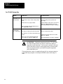
General Troubleshooting Aids 51
. . . . . . . . . . . . . . . . . . . . . . . . . . .
For 1770-M11 System Only 52
. . . . . . . . . . . . . . . . . . . . . . . . . . . .
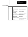
For 1770-M11 System Only 53
. . . . . . . . . . . . . . . . . . . . . . . . . . . .
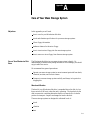
Care of Your Mass Storage System A1. . . . . . . . . . . . . . . . . .
Objectives A1. . . . . . . . . . . . . . . . . . . . . . . . . . . . . . . . . . . . . . . . .
Care
of Y
our Winchester Disk Drive A1. . . . . . . . . . . . . . . . . . . . . . .
MicroFloppy
Information
A3. . . . . . . . . . . . . . . . . . . . . . . . . . . . . .
Never A4
. . . . . . . . . . . . . . . . . . . . . . . . . . . . . . . . . . . . . . . . . . . .
Always A4
. . . . . . . . . . . . . . . . . . . . . . . . . . . . . . . . . . . . . . . . . . .
Front View Hardware Features A5
. . . . . . . . . . . . . . . . . . . . . . . . . .
Back View Hardware Features A6
. . . . . . . . . . . . . . . . . . . . . . . . . .
How to Insert Your MicroFloppy A6
. . . . . . . . . . . . . . . . . . . . . . . . .
How to Remove Your Microfloppy A8
. . . . . . . . . . . . . . . . . . . . . . . .
1770 M11 Mass Storage System B1. . . . . . . . . . . . . . . . . . . . .
Objectives B1. . . . . . . . . . . . . . . . . . . . . . . . . . . . . . . . . . . . . . . . .
Introduction B1
. . . . . . . . . . . . . . . . . . . . . . . . . . . . . . . . . . . . . . . .
Hardware Features B1
. . . . . . . . . . . . . . . . . . . . . . . . . . . . . . . . . .
File Management Features B2
. . . . . . . . . . . . . . . . . . . . . . . . . . . . .
GA Basic Command and Function Set B3
. . . . . . . . . . . . . . . . . . . . .
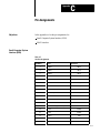
Pin Assignments C1. . . . . . . . . . . . . . . . . . . . . . . . . . . . . . . .
Objectives C1. . . . . . . . . . . . . . . . . . . . . . . . . . . . . . . . . . . . . . . . .
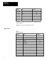
Small Computer System Interface (SCSI) C1
. . . . . . . . . . . . . . . . . . .
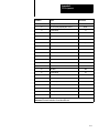
RS422 Interface C2
. . . . . . . . . . . . . . . . . . . . . . . . . . . . . . . . . . . . .
Specifications D1. . . . . . . . . . . . . . . . . . . . . . . . . . . . . . . . . .
Objectives D1. . . . . . . . . . . . . . . . . . . . . . . . . . . . . . . . . . . . . . . . .
Mass Storage Systems D1
. . . . . . . . . . . . . . . . . . . . . . . . . . . . . . . .
Winchester Hard Disk Drive (Formatted) D3
. . . . . . . . . . . . . . . . . . .
Microfloppy Disk Drive D5
. . . . . . . . . . . . . . . . . . . . . . . . . . . . . . . .
Microfloppy
Diskette
D5. . . . . . . . . . . . . . . . . . . . . . . . . . . . . . . . . .
Internal Power Supply D6
. . . . . . . . . . . . . . . . . . . . . . . . . . . . . . . .

Chapter
1
11
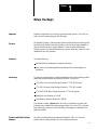
Before You Begin
Read this chapter before you install your mass storage system. It will tell you
how to use this manual properly and efficiently.
We designed a family of mass storage systems with Winchester technology that
interfaces with other Allen-Bradley products. you can store large quantities of
data on hard disk or micro-floppy diskettes. There are three unique mass
storage systems. This manual describes each system, what they connect to, and
summarizes how they interface.
We assume that you:
are familiar with fundamental computer technology
have access to our related publications through a local sales engineer or
distributor.
To make this manual easier to read and understand, we avoid repeating product
names and acronym definitions wherever possible. We refer to:
1770-M10 Universal Mass Storage System as “1770-M10 system”
1770-M11 Processor Mass Storage System as “1770-M11 system”
1770-M12 PC/M Mass Storage System as “1770-M12 system”
Random Access Memory as “RAM”
Disk Memory Interface Module as “DMIM”
This manual contains a glossary that will help you familiarize yourself with
technical terms related to the mass storage systems. For a list of PC words and
their definitions, contact your Allen-Bradley sales engineer or distributor for
publication SD60.
We refer to related products throughout this manual. Table 1.A lists each
product with its catalog number for your ordering convenience.
Important
Purpose
Audience
Vocabulary
Products with Their Catalog
Numbers

Before You Begin
Chapter 1
12
Table 1.A
AllenBradley
products W
ith Catalog Numbers
Product Catalog Number
Universal Mass Storage System 1770M10
Processor Mass Storage System 1770M11
Programmable Controller/Management 1770M12
Microfloppy Diskettes 1770MXA (box of ten)
Diagnostics Cartridge for the 1770M11 Mass
Storage System
1770MDA
Microfloppy Head Cleaning Diskette 1770MMA
Rack Mounting Hardware Kit 1770MRA
Cable (with 1770M10 system) P/N 966 18901
Twinaxial Cable (used with 1770M11 system) 1770CD
Cable (with 1770M12 system) P/N 96628901
Advisor 2
Color Graphic System
6171Series
Peripheral Communication Module 175GA
Programmable Controller/Management System
(PC/M) Ladder Diagram Translator Software
6060WAF3, WBF3
Data Cartridge Recorder 1770SB
Industrial Terminal 1770T4
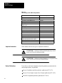
In this manual, there are two types of important information:
ATTENTION: : Inform you where personal injury may occur if
you do not follow the written procedure.
ATTENTION: : Inform you where damage to your equipment may
occur if you do not follow the written procedure.
To provide you with more information about the products associated with the
mass storage systems, we published:
Advisor 2 Installation and Start-up Guide, (publication 6171-6.7.2)
Advisor 2 Color Graphic System User’s Manual (publication 6171-6.5.2)
GRAFIX2 Programming Manual (publication 6171-6.4.2)
Important Information
Related Publications

Before You Begin
Chapter 1
13
Peripheral Communication Module User’s Manual, publication 1775-6.5.4,
(formerly 1775-808)
PC/M Ladder Diagram Translator Software, publication 1770-6.5.6 (formerly
1770- 821)
Data Cartridge Recorder User’s Manual, publication 1770-6.5.4, (formerly
1770- 806)
We will be releasing new information to add to this manual. Complete the
address card at the back of this manual to receive your publication updates.

Chapter
2
21
Hardware Features of the Mass Storage
System
In this chapter you will read about:
hardware features of the mass storage systems
internal components of the mass storage systems
cables required for the mass storage systems
Chapter 3 describes how to install your mass storage systems.
The family of mass storage systems includes three independent units with a
compatible interface system that lets you transmit and store information
between other Allen–Bradley products. There are three mass storage systems.
Table 1.B describes the type of interface system with each mass storage system.
Table 1.B
Summary
of the Mass Storage Systems
Catalog Number Storage Capacity Compatible with Type of Interface
1770-M10 Universal Mass Storage
System
One hard disk:
22.5 Mbytes
One 3-1/2 inch micro-floppy:
655,360 bytes
Advisor 2
TM
Color Graphic System
Other 1770-M10 systems
1770-M11 system
Small Computer System Interface
SCSI
1770-M11 Processor Mass Storage
System
One hard disk:
22.5 Mbytes
One 3-1/2
micro-floppy:
655,360 bytes
PLC-3 Peripheral Communication
Module
Disk Memory Interface Module DMIM
1770-M12 PC/M Mass Storage
System
One hard disk:
17.5 Mbytes
Programmable Controller/
Management System
RS422
Chapter Objectives
Product Description

Hardware Features of the Mass Storage
Systems
Chapter 2
22
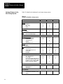
Table 2.B identifies the hardware for each mass storage system.
Table 1.C
Hardware
for Each Mass Storage System
1770-M10 1770-M11 1770-M12
Front View
Indicators
• Hard Disk
• Micro-floppy
• Power
• Restart
X
X
X
-
X
X
X
X
X
-
X
-
Pushbuttons
• Eject
• Restart
X
-
X
X
-
-
Other
• Access Slot for Micro-floppy
X X -
Back View
Communication Channels
• Parallel Channel Out J20
• Parallel Channel In J21
• Serial Channel J22
• Test J23
• RS422 Interface J24
X
X
-
-
-
X
-
X
X
-
X
-
-
-
X
Switches
• Power
• Baud Rate
X
-
X
X
X
-
Other
• Power Connect
• 120/220 V AC electrical card
• Fan and Filter
• Fuseholder
X
X
X
X
X
X
X
X
X
X
X
X
Internal Components
• Winchester Hard Disk Drive
• Micro-floppy Disk Drive
• Power Supply
• Disk Controller Module with Small Com-
puter Systems Interface Module (SCSI)
• Disk Memory Interface Module (DMIM)
• RS422 to SCSI Interface Module
X
X
X
X
-
-
X
X
X
X
X
-
X
-
X
X
-
X
Cables
• P/N 629678-01 (for power)
• P/N 966189-01
• P/N 966289-01
X
X
-
X
-
-
X
-
X
Program Diskette
• Operating System for PLC-3 Peripheral
Communication Module/Mass Storage
System
- X -
Hardware Features for the
Mass Storage System

Hardware Features of the Mass Storage
Systems
Chapter 2
23
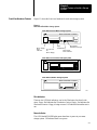
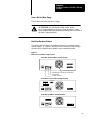
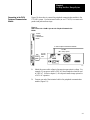
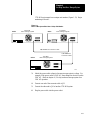
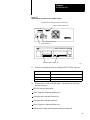
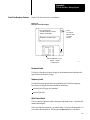
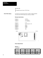
Figure 1.1 shows the front view hardware for each mass storage system.
Figure 1.1
Front
V
iew of Each Mass Storage System.
M12
M11
1770–M10 Universal Mass Storage System
1770–M11 Processor Mass Storage System
1770–M12 PC/M Mass Storage System
Micro–floppy
Disk
Indicator
Access Slot
for
Micro–floppy
Eject
Pushbutton
Winchester
Disk Indicator
Winchester
Hard Disk Storage
MASS STORAGE SYSTEM
MASS STORAGE SYSTEM
MASS STORAGE SYSTEM
11923
Disk Indicators
There are two LED disk indicators; one for the Winchester, the other for the
micro–floppy. Red indicates the Winchester of micro–floppy. Red indicates the
Winchester or micro–floppy is being accessed. Off indicates that neither are in
use.
Power Indicator
This LED labeled POWER lights green when there is power to your mass
storage system. Off indicates there is no power.
Front View Hardware Features

Hardware Features of the Mass Storage
Systems
Chapter 2
24
Restart Indicator (System Fault)
This LED labeled RESTART lights red when either:
the system cannot successfully start from the micro–floppy or Winchester
there is an internal fault detected on the Disk Memory Interface Module
(DMIM)
Or when one of the following conditions occurs:
download fault
Random Access Memory (RAM) parity error
system fault
hardware malfunction
module fault
Off indicates normal operation.
Restart Pushbutton
When you press this red pushbutton labeled RESTART, it:
causes the DMIM to load the 1770–M11 operating system program from the
micro–floppy; if there is not micro–floppy, the DMIM loads the operating
system from the Winchester disk drive
performs a power–up diagnostic check
Eject Pushbutton
Press the black eject pushbutton to release the micro–floppy from the access
slot. Then, remove the micro–floppy and store it in a vertical position inside the
original box.
We describe the care and use of micro–floppies in appendix A.

Hardware Features of the Mass Storage
Systems
Chapter 2
25
Access Slot for Micro-floppy
This is where you insert your micro–floppy.
ATTENTION: Use only double–sided, double–density,
micro–floppy diskettes in the micro–floppy disk drive. Using
single–sided diskettes may permanently damage the drive heads of
the micro–floppy disk drive.
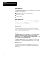
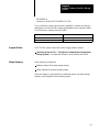
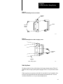
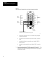
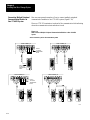
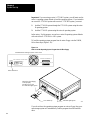
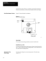
Back View Hardware Features
This section describes back view hardware features for each mass storage
system (Figure 1.2). Chapter 3 describes how to connect each mass storage
system from its communication channel to each compatible product.
Figure 1.2
Back
V
iew of each Mass Storage System
POWER
POWER
POWER
BAUD RATE
1 2 3
1770–M10 Universal Mass Storage System
1770–M11 Processor Mass Storage System
1770–M12 PC/M Mass Storage System
Fan and Filter Location
120/220V AC electrical card location
Fuseholder
Power Connect
11923A
IN OUT

Hardware Features of the Mass Storage
Systems
Chapter 2
26
Parallel Channel In J21
This communication port labeled PARALLEL CHANNEL IN J21 allows you to
connect the 1770–M10 system to:
Allen–Bradley’s Advisor 2TM Color Graphic System
Other 1770–M10 Systems
1770–M11 System
Parallel Channel Out J20
This parallel communication port, labeled PARALLEL CHANNEL OUT J20
allows you to expand memory capacity by connecting another 1770–M10
system to this port. Also, the 1770–M12 system connects to the programmable
controller/management system (PC/M) at this port.
Serial Channel J22
This communication port, labeled SERIAL CHANNEL J22 has six slotted
screws. It is where the twinaxial cable connects from the 1770–M11 system to
the PLC–3 peripheral communication module.
Test J23
Using the port labeled TEST J23, you can test the 1770–M11 system’s internal
components. Connect the data cartridge recorder to load the diagnostics
cartridge for the 1770–M11 system; then connect the industrial terminal (or any
RS–232 terminal) to monitor the program’s result.
The diagnostic cartridge for the 1770–M11 system (cat. no. 1770–MDS) can
test up to three 1770–M10 systems when connected to the 1770–M11 system.
RS422 Interface J24
This communication port, labeled RS422 INTERFACE J24 allows you to
connect the 1770–M12 system to the programmable controller/management
system (PC/M).

Hardware Features of the Mass Storage
Systems
Chapter 2
27
Power Switch
This is an on/off switch. We labeled it for international use:
If you select Then power is And POWER indicator is
1 on green
0 off off
Power Connect, 120/220V AC Electrical Card, Fuse Holder J19
This is a multi purpose module. The power connect is where you connect the
power cable to a power source. We describe cables later in this chapter.
The fuse holder houses a 5 A, 250V fuse for 120V operation.
ATTENTION: We ship this product for 120V AC operation. You
must change the electrical card if you are using a 220V AC.
Changing the electrical card protects the mass storage system from
overcurrent and overvoltage. You could damage your equipment if
you do not insert the proper side of the electrical cord.
Chapter 4 describes how to change the electrical card for 220V AC operations.
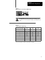
Baud Rate Switch
Baud is the rate at which communication signals from the 1770–M11 system are
transmitted to the PLC–3 peripheral communication module. The chart below
interprets the three positions on this switch labeled BAUD RATE:
Position For Communication Rate
1 57.6kbaud for 10,000 feet (max)
2 115.2kbaud for 5,000 feet (max)
3 230.4kbaud for 200 feet (max)
Notice that the faster the communication rate, the shorter the distance over
which the device can communicate.
Fan and Filter Location
An internal fan circulates air to cool the mass storage system.

Hardware Features of the Mass Storage
Systems
Chapter 2
28
The re–usable foam filter traps dirt from the air. When the filter is dirty, wash it
with warm water and a mild detergent. Do not use an abrasive detergent.
After you wash the filter, air dry it completely before replacing it.
ATTENTION: Do not operate your mass storage system without the
filter in place. Damage to your mass storage system may occur.
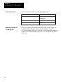
For Information About Read Appendix
Winchester hard disk specifications D
Micro-floppy media information and specifications A,D
Power supply specification D
SCSI specification
(small computer system interface)
C
DMIM specification
(disk memory interface module)
B
RS422 interface specification C
Each mass storage system comes with a cable(s) labeled with a part number
(P/N):
1770–M10 Universal Mass Storage System
P/N: 629678–01
Connects to: POWER CONNECT J19
P/N: 966189–01
Connects to: PARALLEL CHANNEL IN J21 or PARALLEL CHANNEL
OUT J20
1770–M11 Processor Mass Storage System
P/N: 629678–01
Connects to: POWER CONNECT J19
1770–M12 PC/M Mass Storage System
P/N: 629678–01
Connects to: POWER CONNECT J19
Internal Components
Cables

Hardware Features of the Mass Storage
Systems
Chapter 2
29
P/N 966289–01
Connects to: PARALLEL CHANNEL OUT J20
If you would like to make your own cables, appendix C contains the cable pin
assignments. Here are the 3M Company part numbers for the connector cables.
You will need two connectors for each cable:
3M Company Part Number Mass Storage System
3564-1002 or equivalent 1770-M10
3636-100 or equivalent 1770-M12
The 1770–M11 system comes with a micro–floppy diskette, labeled:
Operating System for PLC–3 Peripheral Communication Module/Mass
Storage Systems. It contains the software to be executed by the DMIM.
In this chapter you read about:
hardware feature of the mass storage systems
cables required for the mass storage systems
In the next chapter, we describe how to install and connect your mass storage
system to each compatible Allen–Bradley product.
Program Diskette
Chapter Summary

Chapter
3
31
Installing Your Mass Storage System
In this chapter you will read how to:
install your mass storage system
connect your mass storage system to other Allen-Bradley products
Chapter 4 describes how to operate your mass storage system.
Your mass storage system comes in a re-usable shipping box. Save this box and
foam packing material to transport your mass storage system to different
locations.
Mount your mass storage system in an area away from machines which cause
vibration and shock. Shock levels beyond those noted in the specification
(appendix A) may result in loss of oxide media or head misalignment (i.e., disk
failure), and/or permanent loss of all recorded data. See appendix A for further
information regarding shock and vibration.
There are two ways to install your mass storage system:
19 inch rack mount (must meet with EIA spacing requirements)
table top mount
Rack Mount
When you order the optional rack mounting hardware kit (cat. no. 177-MRA)
you’ll receive the following:
two mounting brackets
two handles
four flat-headed machine screws
four self-tapping screws
Chapter Objectives
Receiving Your System
Locating Your System
Installing Your System

Installing Your Mass Storage System
Chapter 3
32
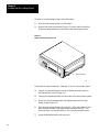
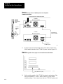
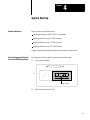
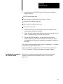
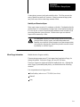
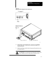
To mount your mass storage system, follow these steps:
1. Place the mass storage system on a flat surface.
2. Remove both front corner inserts (Figure 1.3) using a small screwdriver.
Double-faced tape holds this corner insert to the mass storage system.
Figure 1.3
Remove
Both Front Corner Inserts
Front corner insert
11958
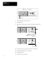
The handles are optional hardware. Skip step 3 if you do not want this option.
3. Connect each mounting bracket with each handle and secure with two
flat-head machine screws (Figure 1.4).
4. Line up each mounting bracket over the corner of the mass storage system.
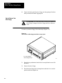
5. Secure two (per mounting bracket) self-tapping screws into the mass
storage system (Figure 1.5).
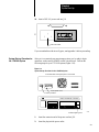
6. Place the mass storage system onto your rack. Allow four inches of clear
space between the back of the mass storage system and the wall. This
allows the fan to circulate filtered air to cool your mass storage system.
7. Secure the mounting bracket onto your rack.

Installing Your Mass Storage System
Chapter 3
33
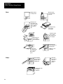
Figure 1.4
Connect
the Mounting Bracket to the Handle
Flathead
Machine
Screws
Mounting
Bracket
Handle
11959
Figure 1.5
Sure the Mounting Brackets with Selftapping Screws
Side View
of
Mass Storage System
Selftapping
Screws
11960
Table Top Mount
We place protective feet on the bottom of each mass storage system. This will
guard the mass storage system against slippage while it is on your table or desk
top.
When you place your system on the table, be sure that it is level and allow four
inches of clear space between the mass storage system and the wall. The fan
circulates filtered air to cool your mass storage system.

Installing Your Mass Storage System
Chapter 3
34
Here is a connection summary for each mass storage system.
Mass Storage System Connects to
1770M10 Universal Mass Storage System Advisor 2
TM
Color Graphic System
1770M10 System
1770M11 System
1770M11 Processor Mass Storage System PLC3 Peripheral Communication Module
1770M12 PC/M Mass Storage System Programmable Controller/Management
System
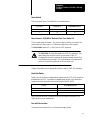
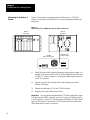
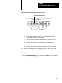
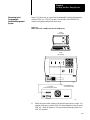
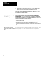
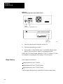
There is an internal switch assembly that contains eight switches (Figure 1.6)
located on the Small Computer Systems Interface (SCSI) module of the
1770-M10 system. Remove the top cover and set only the first three switches to
an address value corresponding to your specific 1770-M10 system unit number
(Table 1.D).
Product Connections
Before you Connect the
1770M1 System

Installing Your Mass Storage System
Chapter 3
35
Figure 1.6
Only
Set Switches 1,2, and 3 for the 1770M10 System
ATTENTION: Never set the internal switch assembly for the
1770-M11 or 1770-M12 systems. Damage to your equipment may
occur.
Table 1.D
1770M10
Switch Assembly Settings
1770M10 System Unit Number SW1 SW2 SW3
0 ON ON ON
1 OFF ON ON
2 ON OFF ON
3 OFF OFF ON
4 ON ON OFF
5 OFF ON OFF
6 ON OFF OFF
7 OFF OFF OFF
Now you are ready to connect to your Advisor 2 System.
Page is loading ...
Page is loading ...
Page is loading ...
Page is loading ...
Page is loading ...
Page is loading ...
Page is loading ...
Page is loading ...
Page is loading ...
Page is loading ...
Page is loading ...
Page is loading ...
Page is loading ...
Page is loading ...
Page is loading ...
Page is loading ...
Page is loading ...
Page is loading ...
Page is loading ...
Page is loading ...
Page is loading ...
Page is loading ...
Page is loading ...
Page is loading ...
Page is loading ...
Page is loading ...
Page is loading ...
Page is loading ...
Page is loading ...
Page is loading ...
Page is loading ...
Page is loading ...
Page is loading ...
Page is loading ...
Page is loading ...
Page is loading ...
Page is loading ...
Page is loading ...
Page is loading ...
Page is loading ...
Page is loading ...
Page is loading ...
Page is loading ...
Page is loading ...
Page is loading ...
Page is loading ...
Page is loading ...
Page is loading ...
Page is loading ...
Page is loading ...
Page is loading ...
Page is loading ...
Page is loading ...
Page is loading ...
Page is loading ...
-
 1
1
-
 2
2
-
 3
3
-
 4
4
-
 5
5
-
 6
6
-
 7
7
-
 8
8
-
 9
9
-
 10
10
-
 11
11
-
 12
12
-
 13
13
-
 14
14
-
 15
15
-
 16
16
-
 17
17
-
 18
18
-
 19
19
-
 20
20
-
 21
21
-
 22
22
-
 23
23
-
 24
24
-
 25
25
-
 26
26
-
 27
27
-
 28
28
-
 29
29
-
 30
30
-
 31
31
-
 32
32
-
 33
33
-
 34
34
-
 35
35
-
 36
36
-
 37
37
-
 38
38
-
 39
39
-
 40
40
-
 41
41
-
 42
42
-
 43
43
-
 44
44
-
 45
45
-
 46
46
-
 47
47
-
 48
48
-
 49
49
-
 50
50
-
 51
51
-
 52
52
-
 53
53
-
 54
54
-
 55
55
-
 56
56
-
 57
57
-
 58
58
-
 59
59
-
 60
60
-
 61
61
-
 62
62
-
 63
63
-
 64
64
-
 65
65
-
 66
66
-
 67
67
-
 68
68
-
 69
69
-
 70
70
-
 71
71
-
 72
72
-
 73
73
-
 74
74
-
 75
75


Allen-Bradley 1770-M10 Installation guide
- Type
- Installation guide
Ask a question and I''ll find the answer in the document
Finding information in a document is now easier with AI
Related papers
-
Allen-Bradley PLC-3 Series Quick start guide
-
-
Allen-Bradley SLC 500 Operating instructions
-
-
-
-
-
-
-
Other documents
-
HQ W7-54224-HQ Datasheet
-
Rasonic RPC-J21 User manual
-
Zenith Z-100 Series User manual
-
-
-
Audio Authority 1770 User manual
-
 Rockwell Automation PanelView Plus 1250 User manual
-
 Rockwell Automation CDN366 Specification
-
 Mitsubishi Electronics T-60 User manual
-
Ingersoll-Rand CENTAC Technical Reference Manual


