
Form CP-OPT-GMK (6-16), P/N 208831 R3, Page 1
Instructions for Installing Replacement Gear Motor Kit
Applies: Modulating Gas Control Options AG39, AG40, AG41 & AG42
on Model Series SC & Model Series RP
Form CP-OPT-GMK (6-16)
Gear Motor Replacement Kit includes a new factory-assembled ue
duct and combustion air damper with a factory-wired gear motor
installed plus three new replacement gaskets
Sizes 100, 125,
150, 175, 200,
225,250, 300
Size 400
Kit P/N 208474 208475
Components: Qty P/N P/N
Factory-assembled and Wire Flue Duct and Combustion Air
Damper Assembly with Gear Motor (See FIGURE 1)
1 207975 207976
Cover Plate Gasket 1 41996
Venter Seal Gasket 1 44695
Flue Outlet Duct Gasket 1 31900
Obsoletes RZ-NA CP-OPT-GMK (Version A)
This kit is designed to replace the solenoid actuator with a gear motor on heaters
equipped with a modulating gas control Option AG39, AG40, AG41 or AG42. To
facilitate replacement, the new ue duct, combustion air damper and gear motor is
factory-assembled and wired for change out.
Application /
Components
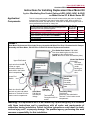
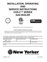
FIGURE 1
Gear Motor Replacement Kit includes Factory-Assembled & Wired Flue Duct & Combustion Air Damper
Assembly with Gear Motor, P/N 207975 or P/N 207976 & three Replacement Gaskets.
Flue Outlet Duct Gasket, P/N 31900
Use when attaching the new flue duct
assembly to the collection box.
(NOTE: Be sure to reuse the restrictor plate.)
Venter Seal Gasket
P/N 44695
Use when
re-installing
venter
housing on
side of flue
duct
Cover Plate
Gasket
P/N 41996
Use when
reattaching cover
plate
Time Delay Relay
P/N 206146
with brown wire attached to
Terminal 7 in the heater control
compartment
15 MFD
Capacitor
P/N 206145
Terminal Block
Connections 85, 86
and 87
Gear Motor
P/N 206144
with damper
linkage
Black wire from the NO
terminal on lower end-switch
attaches to Terminal 88 in the
heater control compartment
Lower End
Switch
Purple wire from the NO
terminal on upper
end-switch attaches to
Terminal 88 in the heater
control compartment
Upper End Switch
Flue Duct with
Combustion Air
Damper
Warning: This replacement kit is to be installed by a qualied agency in accordance
with these instructions and in compliance with all codes and requirements of
authorities having jurisdiction. Failure to follow instructions could result in death,
serious injury and / or property damage. The qualied agency performing this work
assumes responsibility for this installation.

Form CP-OPT-GMK (6-16), P/N 208831 R3, Page 2
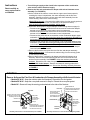
Instructions
1. Turn off the gas supply at the shutoff valve upstream of the combination
valve and turn off the electrical supply.
2. Remove the ue and combustion air damper with solenoid actuator as an
assembly (See FIGURE 2):
a. On the outside of the cabinet, remove the two upper control access panels,
revealing the control compartment, the venter assembly and the ue duct
assembly. Carefully remove the venter motor and wheel assembly from the
venter housing. Remove the venter housing.
(Model RP series only - Disconnect the rubber tubing from the sensing probe on
the venter housing. Leave other end attached to the pressure switch).
Save all venter parts including hardware, will be reused.
b. Disconnect Wires (Refer to original damper actuator wiring shown on page 4):
• Disconnect and discard the black wire that connects the combustion damper
actuator coil to Terminal C in the heater control compartment.
• Disconnect and discard the white wire that connects the combustion damper
actuator coil to Terminal L2 in the heater control compartment.
• Disconnect the yellow wire at its connection on the combustion damper upper
end-switch. (Leave the other end of the yellow wire connected to Terminal 87 in
the heater control compartment. This yellow wire will be reused.)
• Disconnect the orange wire at its connection on the combustion damper lower
end-switch. (Leave the other end of the orange wire connected to Terminal 84
in the heater control compartment. This orange wire will be reused.)
• Disconnect and discard the black wire that connects the combustion damper
lower end-switch to Terminal 88.
c. Remove the ue duct cover plate from the ue duct and damper assembly.
Model SC Series only. - Disconnect the rubber tubing from the sensing probe
on the ue duct cover plate.
d. Remove the ue duct, combustion air damper and solenoid actuator as an
assembly. Remove the screws attaching the ue duct to the collection box
and remove the assembly. See FIGURE 2. Keep the restrictor plate and all
hardware. Discard the ue outlet duct gasket.
On Model SC Series heaters - Remove and keep the sensing probe that is
attached to the side of the ue duct. Discard the remaining assembly illustrated
in FIGURE 2.
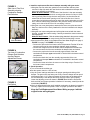
Read carefully as
many parts must be
re-installed.
Flue Duct
Keep solid
cover plate
removed from
the front of
Step 2c
Solenoid
Actuator
Model Series SC
Remove & keep the sensing
probe that was attached to
the side of the flue duct
End Switches
Remove all screws around
the flue duct to remove the
assembly from the flue
collection box
Assembly removed from a unit manufactured prior to 8/2001
End Switches
Solenoid
Actuator
Remove all screws
around the flue
duct to remove the
assembly from the
flue collection box
Flue Duct
Keep solid
cover plate
removed from
the front in
Step 2c
Model Series SC
Remove & keep the sensing
probe that was attached to
the side of the duct flue
Assembly removed from a unit manufactured beginning 8/2001
FIGURE 2
Remove & discard the Flue Duct & Combustion Air Damper Assembly with Solenoid Actuator
• Models RP & SC - Keep the restrictor plate & all hardware. Discard the ue duct gasket.
• Models RP & SC - Keep the cover plate removed in Step 2c. Discard the cover plate gasket.
• Model SC - Remove & keep the sensing probe attached to the side of the ue duct.

Form CP-OPT-GMK (6-16), P/N 208831 R3, Page 3
3. Install the replacement ue duct & damper assembly with gear motor:
a. Using the new ue outlet duct gasket from the kit and the restrictor plate
removed in Step 2d, attach the new ue duct and combustion air damper with
gear motor assembly to the heater.
Model SC Series heaters - On the side of the ue duct in the new assembly,
remove the patch plate to attach the sensing probe removed in Step 2d. Slide
the long sensing tube through the hole and position it so that the tube will
extend into the round venter opening on the side of the ue duct. Use the
screws that had held the patch plate to attach the sensing tube plate to the ue
duct. Slide the rubber tubing (attached to the pressure switch) over the metal
tubing on the side of the ue duct. Be sure tubing is secure.
b. Using the new cover plate gasket, attach the ue duct cover plate removed in
Step 2c to the front of the newly installed ue duct and combustion air damper
assembly.
c. Using the new venter seal gasket and orice plate removed with the venter
housing, re-install the venter housing. Carefully re-attach the venter motor and
wheel assembly.
Model RP Series heaters - Slide the rubber tubing (attached to the pressure switch)
onto the sensing probe on the venter housing. Be sure that the tubing is secure.
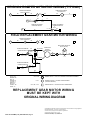
d. Connect the wires. (Refer to the Replacement Gear Motor Diagram on page 4;
FIGURE 1 on page 1 & FIGURE 3 on this page):
• Connect the yellow wire from heater control compartment Terminal 87 to the
common terminal of the new combustion damper upper-end switch.
• Connect the orange wire from the heater control compartment Terminal 84 to
the common terminal of the new combustion air damper lower end-switch.
• Connect the purple wire from the normally-open terminal of the new
combustion air damper upper end-switch to Terminal 88 in the heater control
compartment.
• Connect the black wire from the normally-open terminal of the new
combustion air damper lower end-switch to Terminal 88 in the heater control
compartment.
• Connect the brown wire from the motor run time delay relay to Terminal 7 in
the heater control compartment.
4. Check Operation:
a. Turn on the electric and the gas.
b. Set the system control to “call” for heat.
c. Vary the control settings and observe for proper opening and closing of the
damper. The gear motor was factory set to fully close the damper and to open it
with approximately 1-1/8” (29mm) between the upper edge of the damper and
the duct assembly. If the damper door does not fully close or open properly,
loosen the adjusting screws as shown in FIGURE 4 and slide the end-switch
back and forth until proper operation is obtained. If necessary, carefully bend the
metal blade (FIGURE 5).
d. After it is determined that the newly installed combustion air damper is operating
correctly, replace the access panels. Check for proper operation of the heater.
Keep the Field Replacement Gear Motor Wiring on page 4 with the
original heater wiring diagram.
Lower End-Switch
Upper End-Switch
FIGURE 3
Side view of Flue Duct
Assembly showing
Combustion Damper
End-Switches
FIGURE 4
Top view of Combustion
Damper End-Switches
showing Damper
Adjustment Screws
Loosen screws and slide
End-Switch to adjust damper
FIGURE 5
End-Switch
Metal Blade

Form CP-OPT-GMK (6-16), P/N 208831 R3, Page 4
Specications & illustrations subject to change without notice and without incurring obligations.
©Nortek Global HVAC, LLC 2016. All rights reserved.
All marks are the property of their respective organizations.
O’Fallon, MO I Printed in U.S.A. (6/16)
FORM CP-OPT-GMK (6-16), PN208831 R3
-
 1
1
-
 2
2
-
 3
3
-
 4
4


Ask a question and I''ll find the answer in the document
Finding information in a document is now easier with AI
Related papers
-
Reznor RP Installation guide
-
Reznor SSCBL Installation guide
-
-
-
-
-
-
-
-
Other documents
-
Crown Boiler Cayman Installation guide
-
Crown Boiler CWI345 User manual
-
 New Yorker Boiler CGS50CNI-H Installation guide
-
-
HTP Heavy Duty Gas Water Heater Installation guide
-
Crown Boiler BSI241 Installation guide
-
Crown Boiler BSI138ENPZZPSU Installation guide
-
-
ICP H8MPT100F14A1 Installation guide
-
