Page is loading ...

I-SC (09-18) PN207696R13, Page 1
— Do not store or use gasoline or other ammable vapors and liquids in the vicinity
of this or any other appliance.
— WHAT TO DO IF YOU SMELL GAS
• Do not try to light any appliance.
• Do not touch any electrical switch; do not use any phone in your building.
• Leave the building immediately.
• Immediately call your gas supplier from a phone remote from the building. Follow
the gas supplier’s instructions.
• If you cannot reach your gas supplier, call the re department.
— Installation and service must be performed by a qualied installer, service agency,
or the gas supplier.
I-SC (09-18) PN207696R13
Supersedes I-SC (05-15) PN207696R12
Applies to: Model SC,
Separated-Combustion
Duct Furnace
INSTALLATION/OPERATION/MAINTENANCE
Model SC
!
WARNING:
FIRE OR EXPLOSION HAZARD
Failure to follow safety warnings exactly could result in serious injury, death, or
property damage.
Be sure to read and understand the installation, operation, and service instructions in
this manual.
Improper installation, adjustment, alteration, service, or maintenance can cause
serious injury, death, or property damage.

I-SC (09-18) PN207696R13, Page 2
Denitions of HAZARD INTENSITY LEVELS used in this Manual
1. DANGER: Failure to comply will result in severe personal injury or
death and/or property damage.
2. WARNING: Failure to comply could result in severe personal injury
or death and/or property damage.
3. CAUTION: Failure to comply could result in minor personal injury
and/or property damage.
WARNING
Gas-red appliances are not designed for use in hazardous atmo-
spheres containing ammable vapors or combustible dust, in atmo-
spheres containing chlorinated or halogenated hydrocarbons, or in
applications with airborne silicone substances (refer to Hazard Levels,
above).
WARNING
Improper installation, adjustment, alteration, service, or maintenance
can cause property damage, injury or death. Read the installation,
operation, and maintenance instructions thoroughly before installing
or servicing this equipment.
WARNING
To ensure safety, follow lighting instructions located on the outlet box
cover (refer to Hazard Levels, above).
1.1 Hazard Labels and Notices
There are warning labels on the unit and throughout this manual. For your safety, read
the denitions below and comply with all boxes labeled CAUTION, WARNING, and
DANGER during installation, operation, maintenance, and service of this heater.
1.0 General
1.0 General .............................................................. 2
1.1 Hazard Labels and Notices............................. 2
1.2 General Installation Information .................... 3
1.3 Warranty ........................................................... 3
1.4 Installation Codes ........................................... 3
2.0 Furnace Location ............................................. 4
3.0 Uncrating and Preparation .............................. 4
3.1 Uncrating and Inspecting ............................... 4
3.2 Preparing for Installation ................................ 4
4.0 Clearances and Dimensions ........................... 5
4.1 Clearances ....................................................... 5
4.2 Dimensions ...................................................... 6
5.0 Suspension and Mounting .............................. 6
6.0 Mechanical ........................................................ 7
6.1 Optional Condensation Drain ......................... 7
6.2 Gas Piping and Pressures .............................. 8
6.3 Venting and Combustion Air .......................... 9
6.4 Duct Furnace Airow .................................... 20
7.0 Electrical Supply and Connections .............. 24
7.1 General ........................................................... 24
7.2 Supply Voltage and Wiring ........................... 24
7.3 Typical Wiring Diagrams ............................... 25
7.4 Thermostat and Control Wiring ................... 27
8.0 Controls ..........................................................27
8.1 Combustion Air Proving Switch .................. 27
8.2 Fan Control .................................................... 27
8.3 Limit Control ................................................. 27
8.4 Gas Controls .................................................. 28
8.5 Pilot Ignition Systems ................................... 31
8.6 Burners, Orices, and Carryover System ... 32
9.0 Commissioning and Startup ......................... 33
9.1 Check the installation prior to startup ........ 33
9.2 Startup ............................................................ 33
9.3 Check installation after startup: .................. 34
10.0 Maintenance and Service ............................ 34
10.1 Maintenance Schedule................................ 34
10.2 Maintenance Procedures ............................ 35
10.3 Troubleshooting .......................................... 37
INDEX .................................................................... 39
INSTALLATION RECORD ..................................... 40
Table of Contents

I-SC (09-18) PN207696R13, Page 3
1.2 General
Installation
Information
Installation should be done by a qualied agency in accordance with the instructions
in this manual and in compliance with all codes and requirements of authorities having
jurisdiction. The instructions in this manual apply to duct furnace Model SC.
WARRANTY: Warranty is void if......
a. Furnaces are used in atmospheres containing ammable vapors or
atmospheres containing chlorinated or halogenated hydrocarbons or any
contaminant (silicone, aluminium oxide, etc.) that adheres to the spark
ignition ame sensing probe.
b. Wiring is not in accordance with the diagram furnished with the heater.
c. Unit is installed without proper clearances to combustible materials.
d. Furnace air throughput is not adjusted within the range specied on the
rating plate.
e. Duct furnace is installed in a process or drying application without factory
authorization. Any use in a process or drying application voids agency
certication.
1.4 Installation
Codes
1.3 Warranty
Refer to the limited warranty form in the "Literature Bag".
The indoor duct furnace models in this manual are design-certied to ANSI and CSA
standards by the Canadian Standards Association. All models are approved for instal-
lation in the United States and in Canada. All furnaces are approved for use with either
natural gas or propane. The type of gas for which the furnace is equipped and the
correct ring rate are shown on the rating plate attached to the unit. Electrical charac-
teristics are shown on the unit rating plate.
These units must be installed in accordance with local building codes. In the absence
of local codes, in the United States, the unit must be installed in accordance with the
National Fuel Gas Code NFPA/ANSI Z223.1 (latest edition). A Canadian installation
must be in accordance with the CSA B149.1 Natural Gas and Propane Installation
Code. These codes are available from CSA Information Services, 1-800-463-6727.
Local authorities having jurisdiction should be consulted before installation is made to
verify local codes and installation procedure requirements.
These separated combustion units are designed and manufactured in accordance with
the ANSI denition of separated combustion. That denition reads, "Separated Com-
bustion System Appliance: A system consisting of an appliance and a vent cap(s) sup-
plied by the manufacturer, and (1) combustion air connections between the appliance
and the outside atmosphere, and (2) ue gas connections between the appliance and
vent cap, of a type(s) specied by the manufacturer but supplied by the installer, con-
structed so that, when installed in accordance with the manufacturer's instructions, air
for combustion is obtained from the outside atmosphere and ue gases are discharged
to the outside atmosphere."
Separated combustion units are designed to separate air for combustion and ue prod-
ucts from the environment of the building in which the unit is installed. Separated com-
bustion appliances are recommended for use in dust laden and some corrosive fume
environments.
Special Installations
(Aircraft Hangars/
Garages)
Installations in aircraft hangars should be in accordance with NFPA No. 409 (latest
edition), Standard for Aircraft Hangars; in public garages in accordance with NFPA
No. 88A (latest edition), Standard for Parking Structures; and for repair garages in
accordance with NFPA No. 88B (latest edition), Standard for Repair Garages. In Can-
ada, installations in aircraft hangars, repair garages, and parking garages should be in
accordance with the requirements of the enforcing authorities and in accordance with
CSA B149 codes.
All Installations
These gas-red products are certied by ANSI Z83 family of standards governing
the safe usage of heating equipment in the industrial/commercial marketplace. This
includes using the heaters in makeup air applications to supply corridor pressurization
in commercial buildings such as oce structures and apartment complexes.

I-SC (09-18) PN207696R13, Page 4
2.0 Furnace
Location
A duct furnace is designed for connection to an inlet and an outlet duct and depends
on an external air handler. Location must comply with the clearances listed in Para-
graph 4.1. There are a variety of factors, such as system application, building structure,
dimensions, and weight, that contribute to selecting the location. Read the installation
information in this manual and select a location that complies with the requirements.
CAUTION: Do not locate the heater where it may be exposed to
water spray, rain or dripping water.
1.0 General
(Continued)
1.4 Installation
Codes
(Continued)
The heaters are not certied as residential heating equipment and should not be used
as such.
Clearances from the heater and vent to combustible construction or material in stor-
age must conform with the National Fuel Gas Code ANSI Z223.1a (latest edition) per-
taining to gas-burning devices, and such material must not attain a temperature over
160°F by continued operation of the heater.
WARNING
These duct furnaces are not certied or approved for use in drying
or process applications. If a duct furnace is to be used in a drying or
process application, contact the factory for application guidelines and
manufacturer's authorization. Without factory authorization, the war-
ranty is void, and the manufacturer disclaims any responsibility for the
duct furnace and/or the application.
Hazards of Chlorine
The presence of chlorine vapors in the combustion air of gas-red heating equipment
presents a potential corrosion hazard. Chlorine will, when exposed to ame, precipitate
from the compound, usually Freon or degreaser vapors, and go into solution with any
condensation that is present in the heat exchanger or associated parts. The result is
hydrochloric acid which readily attacks all metals including 300 grade stainless steel.
Care should be taken to separate these vapors from the combustion process. This may
be done by wise location of the furnace with regard to exhausters or prevailing wind
direction. Remember, chlorine is heavier than air. This fact should be kept in mind when
determining installation locations of heating equipment and building exhaust systems.
3.0 Uncrating and
Preparation
3.1 Uncrating and Inspecting
This furnace was test operated and inspected at the factory prior to crating and was in
operating condition. If the furnace has incurred any damage in shipment, document the
damage with the transporting agency and immediately contact an authorized Reznor
®
distributor. If you are an authorized Distributor, follow the FOB freight policy procedures
as published by Reznor for Reznor
®
products.
Check the rating plate for the gas specications and electrical characteristics of the
furnace to be sure that they are compatible with the gas and electric supplies at the
installation site.
The bottom corners are fastened to the crate with angle clips. Remove the lag screws
from the shipping clips. Remove the clips and return the bolts to the heater legs to
support the corner leg and the heater bottom. Putting the bolts back in the heater
is required.
3.2 Preparing for
Installation
3.2.1 Shipped-Separate Components
Read this booklet and become familiar with the installation requirements of your par-
ticular furnace. If you do not have knowledge of local requirements, check with the
local gas company or any other local agencies who might have requirements concern-
ing this installation. Before beginning, make preparations for necessary supplies, tools,
and manpower.
Vent/Combustion Air
Terminal Kit: Required
on ALL Installations
A vent/combustion air kit (Option CC2 or CC6) including a concentric adapter box is
required for all installations. See page 14 (Option CC6) or page 17 (Option CC2) for a
component list. Be sure all of the factory-supplied and eld-supplied parts needed are
at the job site.

I-SC (09-18) PN207696R13, Page 5
Application Option Shipped Separate Components
Heating/Gas Control
AG7
Thermostat, PN 48033
Makeup Air/Gas Control
NOTE: If an optional
remote console is ordered,
the control switch and
temperature selector
may be mounted on the
console.
AG3 Control Switch, PN 29054
AG8
Control Switch, PN 29054
Sensor & Mixing Tube, PN 48041
AG9
Control Switch, PN 29054
Remote Temperature Selector, PN 48042
Sensor & Mixing Tube, PN 48041
AG15
Control Switch, PN 29054
Remote Temperature Selector, PN 115848
Stage Adder Module, PN 115849
Discharge Air Sensor Holder, PN 115850
Discharge Air Sensor Holder Bracket, PN 213612
AG39
Remote Temperature Selector, PN 174849
Temperature Sensor, PN 133228
Mixing Tube, PN 90323
Some gas control options will have parts either shipped loose with the heater or
shipped separately. If your unit is equipped with any of the gas control options in the
table below, be sure these parts are available at the job site.
Other shipped-separate
options could include a gas
shuto valve, a vertical vent
terminal, a thermostat, an
optional control, and/or a
disconnect switch.
Check to see if there are
any eld-installed options
that need to be assembled
to the furnace prior to
installation.
Top Baffle
Support
Screws B
Bottom
Baffle Support
Brackets
Air Discharge
Direction of Airflow
Screw C
Right
Left
Screws A
Screw C
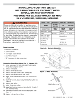
FIGURE 1. Model SC Heat Exchanger Baes
3.2.2 Reversing
Airow by Changing
Direction of Heat
Exchanger Air Baes
Instructions for Reversing Airow through the Heat
Exchanger
1. Remove screws "A". Lift each bae slightly and slide forward,
removing each completely from the heat exchanger.
2. Remove screws "B" and the rear top bae support
assembly. Re-position the assembly on the opposite end
of the heat exchanger and attach.
3. Remove screws "C" and the assembled bottom bae
support and brackets. Plug the holes in the heat
exchanger bottom by re-inserting the screws in the holes.
Position the assembly on the opposite end of the heat
exchanger and attach using eld-supplied sheetmetal
screws.
4. Re-install all of the individual baes by reversing Step 1.
Option Parts
All furnaces are equipped with directional air baes in the heat exchanger area. Fac-
ing the control compartment of the furnace, the standard direction of airow is from left
to right. If the installation requires airow from right to left (when facing the control com-
partment), the position of the directional air baes may be reversed. Refer to FIGURE
1 and follow the instructions to reverse the direction of the airow through the furnace.
4.0 Clearances
and
Dimensions
4.1 Clearances
For safety and convenience, provide clearances as shown in the following table.
Clearance to combustibles is dened as the minimum distance from the heater to a
surface or object that is necessary to ensure that a surface temperature of 90°F above
the surrounding ambient temperature is not exceeded. Minimum clearances are also
listed on the heater rating plate.
Minimum Clearances (Inches (Millimeters))
Top
Sides Bottom
Control Side Side Opposite Controls
To
Combustibles
To
Non-Combustibles
6 (152) 6 (152) plus width of unit 6 (152) 6 (152) 0 (0)

I-SC (09-18) PN207696R13, Page 6
FIGURE 2. Model SC Dimensions (Inches ±1/8 (Millimeters ±3))
NOTE: For duct connection dimensions, see FIGURE 21,
Paragraph 6.4.4.
4.2 Dimensions
5.0 Suspension
and Mounting
Before installing, check the supporting structure to be sure that it has sucient load-
carrying capacity to support the weight.
Net Weight (lb and kg)
Weights
Suspension
SC A B C D E
Dimensions (Inches)
100 22-15/32 13-9/16 32-1/4 8-1/8 6-15/16
125 25-7/32 16-5/16 32-1/4 8-1/8 6-15/16
150/175 30-23/32 21-13/16 32-1/4 8-1/8 6-15/16
200/225 36-7/32 27-5/16 35-1/4 10-3/4 9-15/16
250/300 44-15/32 35-9/16 35-1/4 10-3/4 9-15/16
350 49-31/32 41-1/16 35-1/4 10-3/4 9-15/16
400 55-15/32 46-9/16 35-1/4 10-3/4 9-15/16
Dimensions (Millimeters)
100 571 344 819 206 176
125 641 414 819 206 176
150/175 780 554 819 206 176
200/225 920 694 895 273 252
250/300 1130 903 895 273 252
350 1269 1043 895 273 252
400 1409 1183 895 273 252
Size 100 125 150–175 200–225 250–300 350 400
lb 158 178 203 283 321 350 410
kg 72 81 92 128 146 159 186
Model SC duct furnaces have two-point suspension. See hanger center line dimen-
sions in FIGURE 2, Paragraph 4.2.
At each suspension point, the unit is factory-equipped with a free-turning, female, 1ʺ
NPT pipe hanger. Suspend by connecting the pipe hanger to a 1ʺ threaded pipe. See
suspension method on the left in FIGURE 3. As an alternative method, the factory-
installed pipe hanger may be removed and the heater suspended as illustrated on the
right in FIGURE 3.
4.0 Clearances and Dimensions (Continued)

I-SC (09-18) PN207696R13, Page 7
FIGURE 3. Suspension
Methods
Mounting Supports
Most furnaces will be suspended. If the installation requires that the furnace be
mounted, FIGURE 4 illustrates the requirements for eld-fabricating support feet.
FIGURE 4. Model SC
Mounting Supports
WARNING
Units must be supported level for proper operation. Do not place or add
additional weight to the suspended unit (refer to Hazard Levels, page 2).
6.0 Mechanical
6.1 Optional Condensation Drain for Duct Furnaces
Model SC furnaces are certied for installation upstream or downstream from a cooling
coil. When installed downstream from a refrigeration system, condensation will form;
and therefore, adequate provision must be made to dispose of condensate.
Periodic cleaning of the condensate collection and disposal system is required.
Install drain connection, Option CS1, on the furnace casing; see FIGURE 5.
Seal holes in bottom pan with RTV sealant. Terminate drain outside of the building.
Provide a trap to prevent air from entering the combustion zone. Periodic cleaning of
the condensate collection and disposal system is required. NOTE: Requires a four-
inch (102 mm) minimum clearance under the furnace if a 90° street elbow is used.
FIGURE 5. Option
CS1, PN 31765,
Optional Condensate
Drain Connection
#10-32 x 1”Lg Machine
Screw & Nut
3/4” Pipe Waste Nut
RTV Sealant

I-SC (09-18) PN207696R13, Page 8
6.2 Gas Piping and
Pressures
Gas Connection
Sizing Gas Supply
Lines
WARNING
This appliance is equipped for a maximum gas supply pressure of 1/2 psi, 3.5 kPa,
or 14 inches water column. NOTE: Supply pressures higher than 1/2 psi require
installation of an additional service regulator external to the unit.
Pressure Testing Supply Piping
Test Pressure Above 1/2 PSI: Disconnect the heater and manual valve from the gas
supply which is to be pressure tested. Cap or plug the supply line.
Test Pressure Below 1/2 PSI: Before testing, close the manual valve on the heater.
WARNING
Manifold gas pressure must never exceed 3.5 IN WC for natural gas or
10 IN WC for propane gas.
All piping must be in accordance with requirements outlined in the National Fuel Gas
Code ANSI/Z223.1 (latest edition) or CSA B149.1 and B149.2 (refer to Paragraph
1.4). Gas supply piping installation should conform with good practice and with local
codes.
These separated-combustion units for natural gas are oriced for gas having a heating
value of 1000 (±50) BTU per cubic ft. If the gas at the installation does not meet this
specication, consult the factory for proper oricing.
Seal the opening for the gas supply pipe with the grommet provided.
Pipe joint compounds (pipe dope) shall be resistant to the action of liqueed petroleum
gas or any other chemical constituents of the gas being supplied.
Install a ground joint union and manual shuto valve upstream of the unit control sys-
tem. The 1/8ʺ plugged tapping in the shuto valve provides connection for supply line
pressure test gauge. The National Fuel Gas Code requires the installation of a trap
with a minimum 3ʺ drip leg. Local codes may require a longer drip leg, typically 6ʺ.
WARNING
All components of a gas supply system must be leak tested prior to
placing the equipment in service. NEVER TEST FOR LEAKS WITH AN
OPEN FLAME (refer to Hazard Levels, page 2).
Model SC Sizes 100–250 300–400
Natural Gas 1/2ʺ 3/4ʺ
Propane 1/2ʺ 1/2ʺ
NOTE: The above are gas connection
sizes; not supply line sizes.
After all connections are made, discon-
nect the pilot supply at the control valve
and bleed the system of all air. Reconnect
the pilot line and leak test all connections
by brushing on a soap solution.
Capacity of Piping
Cubic Feet per Hour based on 0.3 IN WC Pressure Drop
Specic Gravity for Natural Gas: 0.6 (1000 BTU/Cubic Feet)
Specic Gravity for Propane Gas: 1.6 (2550 BTU/Cubic Feet)
Pipe
Length
(FT)
Pipe Diameter (IN)
1/2 3/4 1 1-1/4 1-1/2 2
Natural Propane Natural Propane Natural Propane Natural Propane Natural Propane Natural Propane
20 92 56 190 116 350 214 730 445 1100 671 2100 1281
30 73 45 152 93 285 174 590 360 890 543 1650 1007
40 63 38 130 79 245 149 500 305 760 464 1450 885
50 56 34 115 70 215 131 440 268 670 409 1270 775
60 50 31 105 64 195 119 400 244 610 372 1105 674
70 46 28 96 59 180 110 370 226 560 342 1050 641
80 43 26 90 55 170 104 350 214 530 323 990 604
90 40 24 84 51 160 98 320 195 490 299 930 567
100 38 23 79 48 150 92 305 186 460 281 870 531
125 34 21 72 44 130 79 275 168 410 250 780 476
150 31 19 64 39 120 73 250 153 380 232 710 433
175 28 17 59 36 110 67 225 137 350 214 650 397
200 26 16 55 34 100 61 210 128 320 195 610 372
NOTE: When sizing supply lines, consider possibilities of future expansion and increased requirements.
Refer to National Fuel Gas Code for additional information on line sizing.
Manifold or Orice
(Valve Outlet) Pressure
Settings
Measuring manifold gas pressure cannot be done until the heater is in operation. It
is included in the steps of the "Check-Test-Start" procedure in Paragraph 9.0. The
following warnings and instructions apply.
6.0 Mechanical
(Continued)

I-SC (09-18) PN207696R13, Page 9
WARNING
Manifold gas pressure
must never exceed
3.5 IN WC for natural
gas and 10 IN WC for
propane.
CAUTION: DO NOT
bottom out the gas
valve regulator
adjusting screw.
This can result
in unregulated
manifold pressure
causing excess
overre and heat
exchanger failure.
6.3 Venting and
Combustion Air
All separated combustion, power vented units MUST BE equipped with both combus-
tion air and exhaust piping to the outdoors. The unique concentric adapter assembly
designed for use with this heater allows for both combustion air and exhaust piping
with only one horizontal or vertical penetration hole in the building.
These instructions apply to installation and use of the concentric adapter and vent/
combustion air kit (Option CC2 or CC6) designed for use with all Reznor
®
separated-
combustion products. The systems illustrated in this manual are the only venting/com-
bustion air systems approved for these separated combustion units. Do not use this
concentric adapter box with any other products.
WARNING
Do not use an existing venting system. This heater requires installation
of the combustion air/vent system ordered with the unit (either Option
CC2 or Option CC6). Vent installation to be any listed vent system
manufacturer. Do not intermix dierent vent system parts from dierent
manufacturers in the same venting system.
Installation should be done by a qualied agency in accordance with these instructions.
The qualied service agency installing this separated-combustion system is responsible
for the installation.
WARNING
SC Series separated combustion units are not designed or approved
for use in atmospheres containing ammable vapors or atmospheres
highly laden with chlorinated vapors (refer to Hazard Levels, page 2,
and to Hazards of Chlorine in Paragraph 2.0).
For Natural Gas: When the heater leaves the factory, the combination valve is set so
that the outlet gas pressure of a single-stage valve or high re of a two-stage valve is
regulated to 3.5 IN WC Low re on a two-stage valve is set to 1.8 IN WC Inlet supply
pressure to the valve must be a minimum of 5 IN WC or as noted on the rating plate
and a maximum of 14 IN WC NOTE: Always check the rating plate for minimum
gas supply pressure. Minimum supply pressure requirements vary based on size of
burner and the gas control option. Most units require a minimum of 5 IN WC of natural
gas as stated above, but sizes 350 and 400 with electronic modulation require a mini-
mum of 6 IN WC natural gas supply pressure.
For Propane: When the heater leaves the factory, the combination valve is set so that
the outlet gas pressure of a single-stage valve or high re of a two-stage valve is 10 IN
WC Low re on a two-stage valve is set to 5 IN WC Inlet pressure to the valve must be
a minimum of 11 IN WC and a maximum of 14 IN WC
Before attempting to measure or adjust manifold gas pressure, the inlet (supply) pres-
sure must be within the specied range for the gas being used both when the heater is
in operation and on standby. Incorrect inlet pressure could cause excessive manifold
gas pressure immediately or at some future time.
Instructions to Check Valve Outlet (Manifold) Pressure:
1) With the manual valve (on the combination valve) positioned to prevent ow to the
main burners, connect a manometer to the 1/8ʺ pipe outlet pressure tap in the valve.
NOTE: A manometer (uid-lled gauge) is recommended rather than a spring type
gauge due to the diculty of maintaining calibration of a spring type gauge.
2) Open the valve and operate the heater. Measure the gas pressure to the manifold.
To measure the low stage pressure on units equipped with a two-stage valve, discon-
nect the wire from the "HI" terminal on the valve. Be sure to reconnect the wire.
Normally adjustments should not be necessary to the factory preset regulator. If adjust-
ment is necessary, set pressure to correct settings by turning the regulator screw IN
(clockwise) to increase pressure. Turn regulator screw OUT (counterclockwise) to
decrease pressure. Consult the valve manufacturer's literature provided with the fur-
nace for more detailed information.

I-SC (09-18) PN207696R13, Page 10
2) Venter Outlet and
Combustion Air Inlet
NOTE: If using 7ʺ pipe, use a taper type enlarger to attach vent pipe and 7ʺ reducer to
attach combustion air pipe.
Because all separated combustion units MUST BE equipped with both combustion air
and exhaust piping to the outdoors, all have inlet and outlet connections. Combustion
air inlet has a 6ʺ ID collar. Venter outlet has a 6ʺ OD collar.
A minimum of 12ʺ (305 mm) of straight pipe is required at the venter outlet.
The diameter of the venter outlet and combustion air inlet connections for model SC
(all sizes) is 6" (152 mm).
Diameters of Outdoor
Concentric Pipes
3) Pipe Length and
Diameter
Pipe diameter and length requirements listed for the indoor sections of pipe (between
the heater and the concentric adapter box) are in the table below. Vent pipe diameters
and maximum indoor vent lengths apply to both horizontal and vertical vents. Add
all straight sections and equivalent lengths for elbows. The total length of the straight
sections and elbows must not exceed the Maximum Length.
The diameters of the outside (terminal) concentric pipes are shown in the concentric
box connection illustrations in FIGURES 9A and 9B, page 13. The outdoor lengths
depend on the installation. Outdoor vent length requirements are listed in the installa-
tion instructions for the horizontal and vertical vent/combustion air kits on pages 14–20.
6.0 Mechanical
(Continued)
Model SC All Sizes
Inlet Air Pipe Diameter 8ʺ (203 mm)
Vent Pipe Diameter 5ʺ (127 mm)
6.3 Venting and
Combustion Air
(Continued)
• Minimum length between
the heater and the
concentric adapter box is
5 feet (1.5M).
Pipe Diameter and
Maximum Pipe Length
Between the Heater and
the Concentric Adapter
Box
Pipe Diameter and Maximum Pipe Length from Heater to Concentric Adapter
Size
Pipe Diameter
Maximum
Length
Equivalent Straight Length for a
Vent Pipe Inlet Air Pipe 90° Elbow 45° Elbow
inches mm inches mm feet M feet M feet M
100 6 152 6 152 40 12 8 2.4 4 1.2
125 6 152 6 152 50 15 8 2.4 4 1.2
150 6 152 6 152 50 15 8 2.4 4 1.2
175 6 152 6 152 50 15 8 2.4 4 1.2
200
6 152 6 152 50 15 8 2.4 4 1.2
7 178 7 178 70 21 8 2.4 4 1.2
225
6 152 6 152 50 15 8 2.4 4 1.2
7 178 7 178 70 21 8 2.4 4 1.2
250
6 152 6 152 50 15 8 2.4 4 1.2
7 178 7 178 70 21 8 2.4 4 1.2
300
6 152 6 152 50 15 8 2.4 4 1.2
7 178 7 178 70 21 8 2.4 4 1.2
350
6 152 6 152 30 9 8 2.4 4 1.2
7 178 7 178 70 21 8 2.4 4 1.2
400
6 152 6 152 30 9 8 2.4 4 1.2
7 178 7 178 70 21 8 2.4 4 1.2
WARNING
Do not use an existing venting system. This heater requires installation
of the combustion air/vent system ordered with the unit (either Option
CC2 or Option CC6). Vent installation to be any listed vent system
manufacturer. Do not intermix dierent vent system parts from dierent
manufacturers in the same venting system.
All pipe is eld supplied. Requirements are listed for both the vent pipe and the com-
bustion air inlet pipe.
Specic Venting Requirements
Vent Pipe: Vent pipe approved for a Category III appliance OR single-wall, 26-gauge
or heavier galvanized (or a material of equivalent durability and corrosion resistance)
vent pipe is required between the heater and the concentric adapter box.
Double-wall (Type B) vent pipe is required for vent terminal section. The length of vent
pipe that extends through the box and runs concentric through the combustion air pipe
must be one-piece with no joints.
Combustion Air Pipe: Sealed, single-wall galvanized pipe is recommended for com-
bustion air.
1) Type of Pipe

I-SC (09-18) PN207696R13, Page 11
4) Joints and Sealing
Provide pipes as specied in Requirement No. 1, pages 9–10, and seal joints as fol-
lows:
• If using Category III vent pipe run, follow the pipe manufacturer’s instructions for
joining and sealing Category III vent pipe sections.
• If using single-wall vent pipe run, secure slip-t pipe connections using
sheetmetal screws or rivets. Seal all joints with aluminum tape or silicone sealant.
• To seal joints in the single-wall combustion air pipe, secure slip t pipe
connections using sheetmetal screws or rivets. Seal all joints with aluminum tape
or silicone sealant.
• To seal joint in the terminal section of double-wall vent pipe (allowed
ONLY ABOVE the concentric pipes on a VERTICAL vent, follow the pipe
manufacturer’s instructions for joining and sealing double-wall vent pipe sections.
• When joining the terminal section of double-wall vent pipe to the vent cap,
follow the illustrated step-by-step instructions in FIGURE 6.
When joining the terminal section of double-wall vent pipe to a single-wall
or Category III vent pipe run, follow the illustrated step-by-step instructions in
FIGURE 7.
FIGURE 6. Follow
STEPS to join Double-
Wall (Type B) Pipe and
Vent Terminal Cap
(Horizontal or Vertical)
STEP 1:
Place a continual 3/8ʺ bead of silicone sealant
around the circumference of the vent cap col-
lar. This will prevent any water inside the vent
cap from running down the double-wall pipe.
Perform STEP 2 immediately following
STEP 1.
STEP 2:
Insert the collar on the vent cap inside
the inner wall of the double-wall pipe.
Insert as far as possible. Add addi-
tional silicone sealant to fully close
any gaps between the vent cap and
the double wall pipe. This is neces-
sary to prevent water from entering
the double wall pipe.
Secure the vent cap to the double-wall
pipe by drilling and inserting a 3/4ʺ long sheetmetal screw into the vent cap collar.
Do not overtighten screw.
STEP 3:
NOTE: Pipes and vent caps
may not look exactly as
shown in the illustrations.
Instructions apply to both
horizontal and vertical vent
kits.
FIGURE 7. Follow
STEPS to Join Double-
Wall (Type B) Pipe to
Taper-Type Reducer
that Joins It to Single-
Wall or Category III
Vent Run
STEP 1:
On the taper-type reducer, place a
continual 1/4ʺ bead of silicone seal-
ant around the circumference.
STEP 2:
Insert the collar of the reducer into the
inner pipe of the double-wall pipe until
the bead of sealant contacts the inner
pipe creating a sealed joint.
STEP 3:
Spaced equally around the double-
wall pipe, drill three small holes
below the sealant ring. Insert 3/4
inch long sheetmetal screws to
secure the joint. Do not overtighten
screws.
Make this connection a maximum of 6ʺ (152 mm) from the concentric adapter box.
6ʺ to 5ʺ
or 7ʺ to
5ʺ Taper-
Type
Reducer
Perform
STEP 2
immediately
following
STEP 1.
5ʺ ID
Double-
Wall
Pipe

I-SC (09-18) PN207696R13, Page 12
6.3 Venting and Combustion Air (Continued)
Specic Venting Requirements (Continued)
5) Support
Support horizontal runs every 6 feet (1.8M). Support vertical runs of type "B" double-
wall or Category III vent pipe in accordance with the requirements of the pipe manufac-
turer. Support single-wall vertical pipe in accordance with accepted industry practices.
Do not rely on the heater or the adapter box for support of either horizontal or vertical
pipes. Use non-combustible supports on vent pipe.
NOTE: The double-wall vent terminal pipe does not attach to the concentric adapter
box and must be supported during installation.
6) Clearance
All separated combustion installations require a concentric adapter box as illustrated
in FIGURE 8. The concentric adapter box is included in the vent/combustion air kit.
Installation instructions depend on whether the vent system is horizontal (Option CC6)
or vertical (Option CC2).
7) Concentric Adapter
Box
FIGURE 8. Concentric Adapter Box Is Required Part of All Model SC Installations
View of Heater Connection Side
View of Vent Terminal Connection Side
Concentric Adapter
Box Airow
Collar for connecting
indoor portion of the
combustion air pipe
Opening for
double-wall vent
pipe to pass
through the box
Collar for
attaching outside
concentric portion
of the combustion
air pipe
Do not enclose the vent pipe or place pipe closer than 6ʺ (152 mm) to combustible
material.
6.0 Mechanical
(Continued)

I-SC (09-18) PN207696R13, Page 13
When pipe diameters dier, depending on direction of airow, join the pipes with either
a taper-type reducer or enlarger. Refer to illustrations in FIGURE 9A and 9B for pipe
connection requirements at the concentric adapter box.
Do NOT make actual connections until after reading the instructions and length
requirements for installing the vent/combustion air kit. The box connection require-
ments are the same for both vertical and horizontal systems, but the length of
the double-wall pipe varies by installation.
Pipe Connections at the
Concentric Adapter Box
FIGURE 9A.
Concentric Adapter Box
Connections (6ʺ Pipe)
• If using 6ʺ diam-
eter pipes, Model SC
100–400 always require
a 6–5ʺ (152–127 mm)
reducer in the vent pipe.
• If using 7ʺ diameter
pipes (allowed on sizes
200–400), Models SC
200–400 always require
a 7–5ʺ (178–127 mm)
reducer in the vent pipe
and a 6–7ʺ (152–178
mm) enlarger for attach-
ing the combustion air
pipe.
FIGURE 9B. Concentric Adapter Box Connections (7ʺ Pipe)
Horizontal,
Option CC6,
instructions
begin on page 14.
Vertical,
Option CC2,
instructions
begin on
page 17.
Follow the
instructions for
the Vent Terminal
being installed:
Is the Vent Terminal HORIZONTAL OR VERTICAL?

I-SC (09-18) PN207696R13, Page 14
Qty PN Description
1 205883 Complete Horizontal Vent Kit (same as Option CC6)
1 205885 Concentric Adapter Box Assembly (see FIGURE 8, page 12)
1 53316 Screened Exhaust Assembly (illustrated below)
1 205894 Inlet Guard (illustrated below)
4 37661 Screws, #10-16 × 1/2ʺ long, to attach inlet guard
2 207232 Brackets for attaching Concentric Adapter Box (see FIGURE 11, page 15)
1 53335 Tube of High Temperature (450°F) Silicone Sealant
HORIZONTAL VENT
INSTRUCTIONS
Components Required—Factory and Field
FIGURE 10. Parts
in Horizontal Vent
Terminal/Combustion
Air Package
(Option CC6)
Field-supplied
installation
requirements:
• Vent pipes: refer to requirements, page 10
• Combustion air pipes: refer to requirements, page 10
• Taper-type vent pipe diameter reducers and/or increasers as required
• Thimble (not required if wall is of non-combustible construction)
• Flashing
• Sheetmetal screws, tape, and sealant as required
Installation Instructions
for Horizontal Vent Kit
Option CC6
1. Determine the location on the outside wall for the vent terminal. Location must
comply with vent length requirements, Requirement No. 3 on page 10. In most applica-
tions, the terminal would be on a level with the heater mounting height. Allow 1/4ʺ per
foot (6 mm per 305 mm) downward pitch for condensate drain.
The distance of the termination of the horizontal vent from adjacent public walkways,
adjacent buildings, openable windows, and building openings must be in accordance
with local codes or, in the absence of local codes, must conform with National Fuel
Gas Code Z223.2. Local codes supersede all provisions in these instructions and in
the National Fuel Gas Code. Minimum clearances for the horizontal vent terminal are
shown below. Also, select a location that complies with adjoining building clearances
as shown in FIGURE 12, page 16.
Products of combustion can cause discoloring of some building nishes and deteriora-
tion of masonry materials. Applying a clear silicone sealant that is normally used to pro-
tect concrete driveways can protect masonry materials. If discoloration is an esthetic
problem re-locate the vent or install a vertical vent.
Clearances to a
Horizontal Vent
Terminal
Screened
Exhaust
Assembly,
PN 53316
Inlet Guard,
PN 205894
6.3 Venting and Combustion Air (Continued)
6.0 Mechanical (Continued)
Structure
Minimum Clearances for Vent Terminal Location,
All Directions Unless Specied (Feet (Meters))
United States Canada
Forced air inlet within 10 feet (3.1 meters)* 3 (0.9) above
Combustion air inlet of another appliance 6 (1.8)
Door, window, or gravity air inlet
(any building opening)
4 (1.2) horizontal
4 (1.2) below
1 (0.305) above
Electric meter, gas meter, and relief
equipment**
4 (1.2) horizontal 6 (1.8) horizontal
Gas regulator** 3 (0.9) horizontal 6 (1.8) horizontal)
Adjoining building or parapet 6 (1.8)
Adjacent public walkways 7 (2.1) above
Grade (ground level)*** 3 (0.9) above
*Does not apply to the inlet of a direct vent appliance.
**Do not terminate the vent directly above a gas meter or service regulator.
***Consider local snow depth conditions. Vent must be at least 6ʺ (152 mm) higher than anticipated snow depth.

I-SC (09-18) PN207696R13, Page 15
2. Install the Vent Pipe and Combustion Air Pipe Runs: Use the type of pipe speci-
ed in Requirement No. 1, pages 9–10. Comply with requirements in Requirement No.
2, page 10, when attaching pipes to the heater.
Seal all joints. Due to the high temperature, do not enclose the exhaust pipe or place
pipe closer than 6ʺ (152 mm) to combustible material. Extend the runs close to the wall
location selected in Step 1. Support pipes as required in Requirement No. 5, page 12.
3. Prepare a hole through the outside wall for the 8ʺ (203 mm) diameter combus-
tion air pipe. Outside wall construction thickness should be between 1ʺ (25 mm) mini-
mum and 48ʺ (1143 mm) maximum. The larger diameter combustion air pipe serves
as clearance for the vent pipe on non-combustible construction. A thimble may be
required depending on wall construction and/or local codes.
4. Prepare the Concentric Adapter Box
a) Attach the brackets to the box. Follow the instructions in FIGURE 11.
WARNING
All vent terminals must be positioned or located away from fresh air intakes, doors and windows
to preclude combustion products from entering occupied space. Failure to comply could result in
severe personal injury or death and/or property damage.
FIGURE 11. Brackets
for Attaching
Concentric Adapter
Box to Wall
b) Attach the outside portion of the combustion air pipe to the box. Determine
the length by measuring the bracket length from box to wall, plus the wall
thickness, plus 2ʺ (51 mm). The inlet air pipe should extend beyond the outside wall
approximately 2ʺ (51 mm).
Attach the inlet air pipe to the collar of the concentric adapter with sheetmetal screws
and seal.
5. Attach the concentric adapter box to the wall. Insert the combustion air pipe
through the wall. Attach the brackets (FIGURE 11) to the wall. On the outside, caulk or
ash the inlet air pipe. Flashing is eld-supplied.
6. Position the inlet guard over the end of the combustion air pipe. See FIGURE 12,
page 16. Attach the guard to the inlet air pipe with the four 1/2ʺ long screws provided.
7. Determine length and install the double-wall terminal vent pipe.
a) Determine length of pipe. The length of the vent pipe is determined by the instal-
lation within the maximum and minimum requirements. See FIGURE 12, to determine
lengths of each segment and calculate the total length required. The vent pipe extend-
ing through the box and the inlet air pipe must be one piece of double-wall vent pipe
without joints. The transition to the single-wall or Category III vent pipe run, must be
a maximum of 6ʺ (152 mm) from the heater side of the box.
b) Install double-wall terminal vent pipe. Being sure the vent pipe is in the proper
ow direction, slide the end through the box. Position the vent pipe so that it will extend

I-SC (09-18) PN207696R13, Page 16
HORIZONTAL VENT INSTRUCTIONS (Continued)
Top View
FIGURE 12. Installation
of Typical Separated-
Combustion Unit with
Horizontal Vent and
Combustion Air Pipes
(Option CC6)
6.3 Venting and
Combustion Air
(Continued)
6.0 Mechanical
(Continued)
between 16ʺ (406 mm) and 24ʺ (610 mm) past the end of the combustion air pipe and
no more than 6ʺ (152 mm) out of the box toward the heater.
Use a taper-type reducer to attach the 5ʺ double-wall vent pipe to the 6ʺ or 7ʺ single-
wall or Category III vent pipe run. Follow the instructions in FIGURE 7, page 11.
8. Attach the exhaust (vent) cap to the end of the vent pipe. Align the cap so that
its bae strips are positioned on the horizontal and vertical centerlines (see FIGURE
12). Follow the instructions in FIGURE 6, page 11, to attach the exhaust cap.
NOTE: If vent pipe is inserted from outside, cap may be attached before the double-
wall vent pipe is installed. If cap is attached rst, be sure the bae strips are posi-
tioned correctly when attaching the vent terminal pipe to the vent run.
9. Seal the vent pipe. Verify that the double-wall section of vent pipe has a slight
downward drop (1/4ʺ per foot/6 mm per 305 mm) toward the vent terminal end. Use
silicone sealant and seal the circumference of the pipe and the opening of the box.
Seal the area around the pipe completely.
Side View

I-SC (09-18) PN207696R13, Page 17
Qty PN Description
1 205896 Complete Vertical Vent Kit (same as Option CC2)
1 205885 Concentric Adapter Box Assembly (see FIGURE 8, page 12)
1 110052 Exhaust (Vent) Terminal (illustrated below)
1 53330 Combustion Air (illustrated below)
2 207232 Brackets for attaching Concentric Adapter Box (see FIGURE 14, page 18)
1 53335 Tube of High Temperature Silicone Sealant
10. Attach the indoor combustion air pipe. If using 6ʺ pipes, attach the single-wall
combustion air pipe run to the collar on the concentric adapter box with sheetmetal
screws. If using 7ʺ pipe on sizes 200–400, install a taper type enlarger as illustrated In
FIGURE 9B, page 13.
Seal joints with tape or sealant.
Installation of the horizontal vent and combustion air system on your separated-com-
bustion unit is complete. Verify compliance with all venting installation require-
ments, pages 9–13, and illustrated in FIGURE 12.
FIGURE 13. Parts in
Vertical Vent
Terminal/Combustion
Air Package
(Option CC2)
Components Required
(Factory and Field)
VERTICAL VENT
INSTRUCTIONS
Field-supplied
installation
requirements:
• Vent pipes: see requirements, page 10
• Combustion air pipes: see requirements, page 10
• Taper-type pipe diameter reducers and/or increasers as required
• Thimble (not required if wall is of non-combustible construction)
• Flashing
• Sheetmetal screws, tape, and sealant as required
Exhaust
(Vent)
Terminal,
PN 110052
Combustion
Air Inlet,
PN 53330
Installation Instructions
for Vertical Vent/
Combustion Air Kit
(Option CC2)
1. Determine the location of the vent terminal.
Select a location away from fresh air intakes, allowing space for the concentric adapter
box inside. Vent terminal must be located from adjacent buildings as shown in FIGURE
18, page 20.
If more than one vertical concentric vent/combustion air terminal (Option CC2) is being
installed, the minimum spacing between vent centerlines is determined by the mini-
mum outdoor design temperature (most extreme outdoor condition at the site).
Minimum Outdoor Design
Temperature
Minimum Spacing Between Center Lines
of Vent Pipes in Vertical Combustion
Air/Vent Terminals (Option CC2)
°F °C Inches Millimeters
31 or warmer 0 or warmer 36 914
−10 to 30 −23 to −1 60 1524
less than −10 less than −23 84 2134
2. Install the Vent Pipe and Combustion Air Pipe Run: Use the type of pipe speci-
ed (Requirement No. 1, pages 9–10), and comply with the attachment requirements
in Requirement No. 2, page 10. Length must comply with Requirement No. 3, page 10.
Seal all joints. Due to the high temperature, do not enclose the exhaust pipe or place
pipe closer than 6ʺ (152 mm) to combustible material. Provide supports for the pipes.
Extend the runs to close to the roof at the location selected in Step 1 above.
WARNING
All vent terminals must be positioned or located away from fresh air
intakes, doors and windows to preclude combustion products from
entering occupied space. Failure to comply could result in severe
personal injury or death and/or property damage.

I-SC (09-18) PN207696R13, Page 18
FIGURE 14. Brackets
for Attaching
Concentric Adapter
Box to Roof
4. Prepare the Concentric Adapter Box
a) Attach the brackets to the box. Follow the instructions in FIGURE 14.
5. Attach the concentric adapter box to the roof. On the inside, insert the combus-
tion air pipe up through the opening and attach brackets to the roof (see FIGURES
15 and 16). On the outside, ash the combustion air pipe to the roof. Flashing is eld
supplied.
6. Determine the length and install the double-wall vent pipe.
a) Determine the length. See FIGURE 15 to determine the required length of the vent
pipe. The vent pipe extending through the box and the inlet air pipe must be one piece
of double-wall vent pipe without joints.
Determine the minimum length by adding the requirements. Starting at the bottom, the
maximum the vent pipe can extend below the box is 6ʺ (152 mm); plus 6ʺ (152 mm)
through the box; plus length of bracket extending above the box; plus the width of the
roof; plus the height of the outside combustion air pipe above the roof; plus a mini-
mum of 3ʺ (76 mm) beyond the top of the inlet air pipe. Total is the minimum length of
the vent pipe section. If the actual piece of vent pipe is longer, extend it further above
the combustion air pipe. Do not extend it more than 6ʺ (152 mm) below the box.
b) Install the pipe. Being sure the pipe is in the proper ow direction, slide the end into
the box and out through the combustion air pipe. Position the vent pipe so that the end
is no more than 6ʺ (152 mm) below the box. The upper end should extend at least 3ʺ
(76 mm) above the combustion air pipe. NOTE: The double-wall vent pipe does not
attach to the box. The installer must provide support.
Follow the instructions in FIGURE 7, page 11 for connecting the double-wall pipe to the
single-wall pipe or Category III vent pipe run. A taper-type reducer is required.
Seal the circumference of the pipe and the opening of the box with silicone sealant.
Seal the area around the pipe completely.
7. On the outside, slide the combustion air inlet over the vent pipe and fasten the
collar to the combustion air pipe with sheetmetal screws (see FIGURE 17). Seal the
opening at the top between the vent pipe and the combustion air inlet with silicone
sealant to prevent water leakage.
8. Attach the exhaust (vent) cap. See FIGURE 17 and follow the illustrated instruc-
tions in FIGURE 6, page 11.
b) Attach the outside portion of the combustion air pipe to the box. Determine
the length of the combustion air pipe so that dimension ”X” in FIGURE 15 is equal to
the bracket length, plus the roof thickness, plus anticipated snow depth, but does not
exceed 48ʺ (1219 mm) or have less than 18ʺ (457 mm) of pipe above the roof. Attach
the inlet air pipe to the collar of the concentric adapter box with sheetmetal screws.
6.3 Venting and
Combustion Air
(Continued)
6.0 Mechanical
(Continued)
VERTICAL VENT INSTRUCTIONS (CONTINUED)
3. Prepare a hole through the roof for the 8ʺ (203 mm) diameter combustion air
pipe. A thimble may or may not be required depending on building construction and/or
local codes. The larger diameter combustion air pipe serves as clearance for the vent
pipe on non-combustible construction.

I-SC (09-18) PN207696R13, Page 19
FIGURE 15. Assemble Concentric Adapter Box, Outdoor Combustion Air Pipe,
and Double-Wall Vent Pipe
FIGURE 17. Install Combustion Air Inlet and Vent Terminal
FIGURE 16. Slide Attached
Combustion Air Pipe Up
Through Roof
9. Attach the indoor combustion air pipe. Use sheetmetal screws to attach the sin-
gle-wall combustion air pipe run to the collar on the concentric adapter box. Seal with
tape or sealant. If using 7ʺ pipe on sizes 200–400, install a taper type enlarger as illus-
trated in FIGURE 9B, page 13.
SECOND, Install the Exhaust (Vent) Terminal.
Follow the instructions in FIGURE 2, page 3.
FIRST, Install Combustion Air Inlet.
1) Slide the combustion air inlet over the vent pipe.
2) Fasten bottom of inlet to the combustion air pipe
with sheetmetal screws. Be sure not to penetrate
the vent pipe.
3) At the top, completely seal the space between the
vent pipe and the air inlet with silicone.
Double-wall Vent Pipe
Cold Climate NOTE: In geographic
areas where the design ambient is
-10°F or lower, this minimum height
is 24” (610 mm)
Single-wall Combustion Air Pipe

I-SC (09-18) PN207696R13, Page 20
Installation of the vertical vent and combustion air system on
your separated-combustion unit is complete. Verify compliance
with all venting installation requirements, pages 9–13, and in
FIGURE 18.
FIGURE 18. Installation of Unit with Vertical Vent Terminal/Combustion Air Inlet (Option CC2)
Rear
View
Side View
6.3 Venting and Combustion Air (Continued)
6.0 Mechanical
(Continued)
VERTICAL VENT INSTRUCTIONS (CONTINUED)
6.4 Duct Furnace
Airow
6.4.1 Pressure Drop and Temperature Rise by Size
The following chart shows the approved temperature rise range with the required CFM
and the internal Pressure Drop (PD) for each size. Maximum static pressure is 2 IN WC
To determine temperature rise, measure the inlet and outlet temperatures at points not
aected by heat radiating from the heat exchanger.
The duct furnace must be installed on the positive pressure side of the eld supplied
blower. The air throughput must be within the CFM range stated on the heater rating
plate. The air distribution must be even over the entire heat exchanger. Turning vanes
Model SC Series 6 (80% Thermal Ecient)
Size 100 125 150 175 200 225 250 300 350 400
Temp Rise CFM PD CFM PD CFM PD CFM PD CFM PD CFM PD CFM PD CFM PD CFM PD CFM PD
30°F 2465 1.38 3085 1.39 3700 1.00 4320 1.49 4935 1.14 5555 1.48 6170 1.17 7400 1.61 8640 1.87 9875 1.87
40°F 1850 0.78 2310 0.78 2775 0.56 3240 0.81 3700 0.64 4165 0.83 4630 0.66 5555 0.91 6480 1.05 7400 1.05
50°F 1480 0.50 1850 0.50 2220 0.36 2590 0.52 2960 0.41 3330 0.53 3700 0.42 4440 0.58 5185 0.67 5925 0.67
55°F 1345 0.34 1680 0.41 2020 0.30 2355 0.43 2690 0.34 3030 0.44 3365 0.35 4040 0.48 4710 0.55 5385 0.55
60°F 1235 0.29 1540 0.34 1850 0.26 2160 0.36 2465 0.28 2775 0.37 3085 0.30 3700 0.40 4320 0.46 4935 0.46
70°F 1055 0.21 1320 0.25 1585 0.19 1850 0.26 2115 0.21 2380 0.27 2645 0.22 3175 0.30 3700 0.34 4230 0.34
80°F 925 0.16 1155 0.19 1385 0.14 1620 0.20 1850 0.17 2080 0.21 2315 0.20 2775 0.23 3240 0.26 3700 0.26
85°F 870 0.14 1085 0.18 1305 0.13 1525 0.18 1740 0.15 1960 0.19 2175 0.20 2610 0.22 3050 0.23 3485 0.23
90°F 820 0.12 1025 0.16 1235 0.12 1440 0.16 1645 0.13 1850 0.17 2055 0.18 2465 0.20 2880 0.21 3290 0.21
/