Reznor RPB Installation guide
- Category
- Split-system air conditioners
- Type
- Installation guide

Form I-RPB, P/N 131782 R13, Page 1
Form I-RPB (Version F.3)
Obsoletes Form I-RPB (Version F.2)
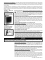
Applies to: Model Series RPB
Outdoor Packaged
Duct Furnace and Blower
Installation / Operation / Maintenance
Model RPB
!
WARNING:
FIRE OR EXPLOSION HAZARD
Failure to follow safety warnings exactly could result in serious injury, death, or
property damage.
Be sure to read and understand the installation, operation, and service instructions in
this manual.
Improper installation, adjustment, alteration, service, or maintenance can cause
serious injury, death, or property damage.
— Do not store or use gasoline or other ammable vapors and liquids in the vicinity
of this or any other appliance.
— WHAT TO DO IF YOU SMELL GAS
• Do not try to light any appliance.
• Do not touch any electrical switch; do not use any phone in your building.
• Leave the building immediately.
• Immediately call your gas supplier from a phone remote from the building. Follow
the gas supplier’s instructions.
• If you cannot reach your gas supplier, call the re department.
— Installation and service must be performed by a qualied installer, service agency,
or the gas supplier.

Form I-RPB, P/N 131782 R13, Page 2
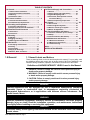
Denitions of HAZARD INTENSITY LEVELS used in this Manual
1. DANGER: Failure to comply will result in severe personal injury or
death and/or property damage.
2. WARNING: Failure to comply could result in severe personal injury
or death and/or property damage.
3. CAUTION: Failure to comply could result in minor personal injury
and/or property damage.
1.1 Hazard Labels and Notices
There are warning labels on the unit and throughout this manual. For your safety, read
the denitions below and comply with all boxes labeled CAUTION, WARNING, and
DANGER during installation, operation, maintenance, and service of this heater.
1.0 General
1.0 General................................................................. 2
1.1 Hazard Labels and Notices .............................2
1.2 General Installation Information .....................3
1.3 Warranty ...........................................................3
1.4 Installation Codes ............................................3
2.0 Furnace Location ................................................ 3
2.1 General Recommendations ............................3
2.2 Combustion Air Requirements .......................3
3.0 Uncrating and Preparation ................................. 3
3.1 Uncrating and Inspecting ................................3
3.2 Preparing the Furnace for Installation ...........4
4.0 Dimensions and Clearances ............................. 4
4.1 Dimensions ......................................................4
4.2 Clearances........................................................5
5.0 Mounting .............................................................. 5
5.1 Weights .............................................................5
5.2 Rigging and Lifting ..........................................5
5.3 Mounting Base and Methods ..........................6
6.0 Mechanical........................................................... 8
6.1 Gas Piping and Pressures ..............................8
6.2 Venting ...........................................................10
6.3 Unit Inlet Air ...................................................11
6.4 Supply Air Discharge ....................................20
6.5 Blowers, Belts, and Drives............................22
7.0 Electrical Supply and Connections ................. 24
7.1 General ...........................................................24
7.2 Supply Voltage and Supply Wiring ..............24
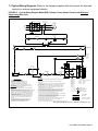
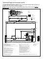
7.3 Typical Wiring Diagrams ...............................25
7.4 Thermostat, Other Optional Controls,
and Control Wiring ........................................27
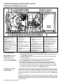
7.5 Electrical Operating Components ................28
8.0 Controls ............................................................. 29
8.1 Gas Controls .................................................29
8.2 Pilot and Ignition Systems ............................33
8.3 Burners and Carryover System ....................34
8.4 Burner Air Adjustment ..................................34
9.0 Check Installation and Startup ........................ 34
9.1 Check the installation prior to startup: ........34
9.2 Startup ...........................................................35
9.3 Check Installation After Startup ...................35
10.0 Maintenance and Service ............................... 36
10.1 Maintenance Schedule ................................36
10.2 Maintenance Procedures ............................36
10.3 Troubleshooting ...........................................38
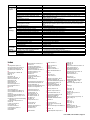
Index......................................................................... 39
INSTALLATION RECORD ...................................... 40
TABLE OF CONTENTS
WARNING
Gas-red appliances are not designed for use in hazardous atmospheres containing
ammable vapors or combustible dust, in atmospheres containing chlorinated or
halogenated hydrocarbons, or in applications with airborne silicone substances. See
Hazard Levels, above.
WARNING
Improper installation, adjustment, alteration, service, or maintenance can cause property
damage, injury or death. Read the installation, operation, and maintenance instructions
thoroughly before installing or servicing this equipment.
WARNING
To ensure safety, follow lighting instructions located on the outlet box cover. See Hazard
Levels, above.

Form I-RPB, P/N 131782 R13, Page 3
1.2 General
Installation
Information
Installation should be done by a qualied agency in accordance with the instructions
in this manual and in compliance with all codes and requirements of authorities having
jurisdiction. The instructions in this manual apply to packaged duct furnace and blower
Model Series RPB.
WARRANTY: Warranty is void if......
a. Furnaces are used in atmospheres containing ammable vapors or
atmospheres containing chlorinated or halogenated hydrocarbons or any
contaminant (silicone, aluminium oxide, etc.) that adheres to the spark
ignition ame sensing probe.
b. Wiring is not in accordance with the diagram furnished with the heater.
c. Unit is installed without proper clearances to combustible materials or
without proper ventilation and air for combustion. (Paragraphs 2.2 & 4.2.)
d. Furnace air throughput is not adjusted within the range specied on the
rating plate.
1.4 Installation
Codes
1.3 Warranty
Refer to the limited warranty form in the "Literature Bag".
The outdoor packaged systems in this manual are design-certied to ANSI and CSA
standards by the Canadian Standards Association. These models are approved for
installation in the United States and in Canada. The furnaces are approved for use
with either natural gas or propane. The type of gas for which the furnace is equipped
and the correct ring rate are shown on the rating plate attached to the unit. Electrical
characteristics are shown on the unit rating plate.
These units must be installed in accordance with local building codes. In the absence
of local codes, in the United States, the unit must be installed in accordance with the
National Fuel Gas Code NFPA/ANSI Z223.1 (latest edition). A Canadian installation
must be in accordance with the CSA B149.1 Natural Gas and Propane Installation
Code. These codes are available from CSA Information Services, 1-800-463-6727.
Local authorities having jurisdiction should be consulted before installation is made to
verify local codes and installation procedure requirements.
2.0 Furnace
Location
2.1 General Recommendations
Location must comply with the clearances listed in Paragraph 4.2. There are a variety
of factors, such as system application, building structure, dimensions, and weight, that
contribute to selecting the location. If equipped with an outside air hood, it is recom-
mended that the inlet to the hood not be facing into the prevailing wind.
Read the installation information in this manual and select a location that complies with
the requirements.
2.2 Combustion Air
Requirements
The combustion air and ue gas openings are carefully designed screened openings
located on the side of each unit just above the control access panel. Location of the
ue opening directly above the air intakes discourages recirculation of combustion
products.
Hazards of Chlorine - The presence of chlorine vapors in the combustion air of gas-
red heating equipment presents a potential corrosion hazard. Chlorine will, when
exposed to ame, precipitate from the compound, usually freon or degreaser vapors,
and go into solution with any condensation that is present in the heat exchanger or
associated parts. The result is hydrochloric acid which readily attacks all metals includ-
ing 300 grade stainless steel.
Care should be taken to separate these vapors from the combustion process. This
may be done by wise location of the furnace with regard to exhausters or prevailing
wind direction. Remember, chlorine is heavier than air. This fact should be kept in mind
when determining installation locations of heating equipment and building exhaust sys-
tems.
3.0 Uncrating and
Preparation
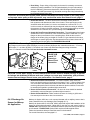
3.1 Uncrating and Inspecting
This furnace was test operated and inspected at the factory prior to crating and was in
operating condition. If the furnace has incurred any damage in shipment, document the
damage with the transporting agency and immediately contact an authorized Reznor
®

Form I-RPB, P/N 131782 R13, Page 4
4.0 Dimensions
and
Clearances
3.2 Preparing the
Furnace for
Installation
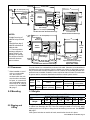
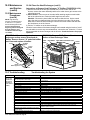
FIGURE 1 -
Dimensions,
Outdoor/ Power-
Vented Model
Series RPB
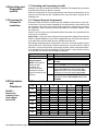
4.1 Dimensions
Size A B C D
Gas Connection
Natural Propane
125
inches
28-5/8 17-3/8 25-7/8 15-1/4 1/2 1/2
mm
727 441 657 387 13 13
150, 175
inches
34-1/8 22-7/8 31-3/8 20-3/4 1/2 1/2
mm
867 581 797 527 13 13
200, 225
inches
39-5/8 28-3/8 36-7/8 26-1/4 1/2 1/2
mm
1006 721 937 667 13 13
250
inches
47-7/8 36-5/8 45-1/8 34-1/2 1/2 1/2
mm
1216 930 1146 876 13 13
300
inches
47-7/8 36-5/8 45-1/8 34-1/2 3/4 1/2
mm
1216 930 1146 876 19 13
350
inches
53-3/8 42-1/8 50-5/8 40 3/4 1/2
mm
1362 1070 1286 1016 19 13
400
inches
58-7/8 47-5/8 56-1/8 45-1/2 3/4 1/2
mm
1470 1210 1426 1156 19 13
Air Openings: Dimensions
Standard Horizontal Air Inlet 19-1/2 (495) x B
Optional Return Air Opening (bottom) 19-1/2 (495) x B
Standard Horizontal Discharge Air Opening 18 (457) x D
Optional Vertical Discharge Air Opening (w/Option AQ5 or AQ8 Plenum) 19-1/2 (495) x B
distributor. If you are an authorized Distributor, follow the FOB freight policy procedures
as published by Reznor for Reznor
®
products.
Check the rating plate for the gas specications and electrical characteristics of the
furnace to be sure that they are compatible with the gas and electric supplies at the
installation site.
3.2.1 Shipped-Separate Components
Read this booklet and become familiar with the installation requirements of your par-
ticular furnace. If you do not have knowledge of local requirements, check with the local
gas company or any other local agencies who might have requirements concerning
this installation. Before beginning, make preparations for necessary supplies, tools,
and manpower.
Check to see if there are any eld-installed options that need to be assembled to the
furnace prior to installation.
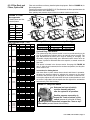
Option Parts - Some gas control options will have parts either shipped loose with the
heater or shipped separately. If your unit is equipped with any of the gas control options
in the table below, be sure these parts are available at the job site.
Other shipped-separate options could include a roof curb, a screened outside air hood,
a gas shutoff valve, a thermostat, a different control switch, a remote console, a manual
fan switch, a vertical vent terminal, a gas supply regulator, and/or a disconnect switch.
Or, if equipped with an optional evaporative cooling module, a water hammer arrestor
or ll and drain or freeze kit could be shipped separately.
3.0 Uncrating and
Preparation
(cont'd)
3.1 Uncrating and Inspecting (cont'd)
Application Option Shipped Separate Components
Heating -- Gas Control AG7 Thermostat, P/N 48033
Makeup Air -- Gas
Control Options
(NOTE: If an optional
remote console
is ordered, the
control switch and
temperature selector
may be mounted on the
console.)
AG3 Control Switch, P/N 29054
AG8
Control Switch, P/N 29054; Sensor & Mixing Tube,
P/N 48041
AG9
Control Switch, P/N 29054; Remote Temperature
Selector, P/N 48042; Sensor & Mixing Tube, P/N 48041
AG15
Control Switch, P/N 29054; Remote Temperature
Selector, P/N 115848; Stage Adder Module, P/N
115849; Discharge Air Sensor Holder, P/N 115850;
Discharge Air Sensor Holder Bracket, P/N 213612
AG39 Remote Temperature Selector, P/N 174849;
Temperature Sensor, P/N 133228; Mixing Tube,
P/N 90323

Form I-RPB, P/N 131782 R13, Page 5
4.2 Clearances
REQUIRED CLEARANCES
Model
Series
Top
Sides Bottom
Control Opposite
To
Combustibles
To Non-
Combustibles
RPB
36"
(915mm)
Width of furnace
plus 6" (152mm)
6"
(152mm)
0 * 0
* When installed on a roof
curb on a combustible
roof, the roof area
enclosed within the curb
must be either ventilated,
left open, or covered with
non-combustible material
which has an "R" value of
at least 5.0. See FIGURE
3A, page 7.
NOTES:
*Height from top of
cabinet to top of curb
cap.
**Height from top of
cabinet to bottom of
cabinet side.
**** The two-position
discharge dampers in
Option AQ8 t in the
discharge air opening.
The damper motor ts
inside the downturn
plenum cabinet.
Provide clearance to combustibles as shown in the table. Clearance to combustibles is
dened as the minimum distance from the heater to a surface or object that is neces-
sary to ensure that a surface temperature of 90°F above the surrounding ambient tem-
perature is not exceeded. Clearance is also required to sides of furnace for combustion
air space and for convenient installation and burner control system service.
5.0 Mounting
Approximate Net Weight (lbs/kg) - Model RPB Series Systems
(blower and furnace sections only)
Size 125 150, 175 200, 225 250, 300 350 400
Weight
lbs 482 520 534 588 630 662
kg 219 236 242 267 286 300
5.1 Weights
5.2 Rigging and
Lifting
Lifting holes are provided for rigging. Use spreader bars when lifting to prevent chains
or cables from damaging the unit. If the unit is being mounted on a roof curb, apply
caulking to the roof curb prior to lifting the unit and setting it on the curb. See FIGURE
3A, page 7.
If the system includes an outside air hood, attach it after the unit is in place.

Form I-RPB, P/N 131782 R13, Page 6
5.3.1 Curb Cap Base
Outdoor systems are equipped with a load bearing curb cap which forms an integral
part of the unit. This curb cap has welded joints and has a "skirt" which ts over a roof
curb to provide a weatherproof installation. Four holes are provided at the curb cap
corners for lifting the unit. These holes do not interfere with unit weatherproong. The
curb cap is not designed to be placed directly on the roof surface. The system
may be mounted on an optional roof curb purchased with the unit, a eld-supplied roof
curb, or eld-supplied supports. If the system has a downturn plenum and/or a bottom
return air opening, a roof curb is recommended to provide a weatherproof installation
as well as more workable clearances for ductwork.
5.3 Mounting Base
and Methods
5.3.2 Mounting
on Field-Supplied
Supports (without a
roof curb)
Prior to installation, be sure that the method of support is in agreement with all local
building codes and is suited to the climate. If considering this type of installation in
snow areas, it is recommended that the 4x4 wooden rails underneath the system be
on cross-support structure at least 12" higher than the roof surface (see support loca-
tions in FIGURE 2B).
Whether the supports are being mounted directly on the roof or being placed "up" on
additional structure, the horizontal length of the system should be supported by two
4x4 treated wooden rails. Cut the rails to the appropriate length (Dimension "A") in FIG-
URE 2A. (NOTE: Although dimensions are included for units with a downturn plenum
cabinet, it is strongly recommended that a full roof curb be used on an installation with
a downturn plenum cabinet and/or a bottom return air duct.)
Space the 4x4 wooden rails (See "B" Dimension, FIGURE 2A) so that the curb cap
"skirt" will t over the edge of the boards with the rails setting inside the horizontal
length of the curb cap.
If the rails are being laid directly on the roof, position them as shown in FIGURE 2A.
Set the system on the rails, leaving the "ends" underneath open for ventilation.
If the treated wooden rails are not being placed directly on the roof surface, cross-
supports should be placed underneath the rails at the ends of the unit and at all cabinet
"joints" (between the blower cabinet and the furnace section and between the furnace
and the optional downturn plenum). See FIGURE 2B.
The eld-supplied, weather-resistant cross-support structure must be adequate for the
weight of the system. Cross-supports should run the entire width of the system sup-
porting the 4x4 wooden rails at the recommended locations (FIGURE 2B).
Blower
Cabinet
Furnace
Section
Field
Supplied
Duct
4x4 Treated
Lumber
= Cross Support Locations
Field
Supplied
Duct
FIGURE 2B - Cross-Support Locations
Whether using an optional roof curb available with the system or a eld-supplied curb,
the curb must be secure, square and level. The top surface of the roof curb must be
caulked with 1/4" x 1-1/4" sealant tape or two 1/4" beads of suitable sealant. The unit
must be sealed to the curb to prevent water leakage into the curb area due to wind
blown rain and capillary action. Except for the curb assembly details which are specic
to the optional roof curb available with the system, the information and requirements
FIGURE 2A - Mounting Support Dimensions (inches/mm)
Model
Series
RPB Size
Standard Heater
and Blower
Package
With Factory-Installed
Downturn Plenum
Cabinet (Option AQ)
All
"A" "A" "B"
125 60-5/8" 84-9/16" 24-5/16"
150, 175 60-5/8" 84-9/16" 29-13/16"
200, 225 60-5/8" 84-9/16" 35-5/16"
250, 300 60-5/8" 84-9/16" 43-9/16"
350 60-5/8" 84-9/16" 49-1/16"
400 60-5/8" 84-9/16" 54-1/2"
125 1540mm 2148mm 618mm
150, 175 1540mm 2148mm 757mm
200, 225 1540mm 2148mm 897mm
250, 300 1540mm 2148mm 1106mm
350 1540mm 2148mm 1246mm
400 1540mm 2148mm 1384mm
5.3.3 Mounting on a
Roof Curb
5.0 Mounting
(cont'd)

Form I-RPB, P/N 131782 R13, Page 7
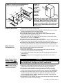
IMPORTANT: Top surface of curb MUST be sealed.
See instructions.
* Illustration is shown with an Option AQ5
or AQ8 downturn plenum. The system
can have a variety of congurations
which affect installation.
• If the system does not have a
downturn plenum, the discharge is
horizontal.
• Downturn plenum Options AQ5 and
AQ8 are factory installed to be lifted
to the roof and set on the roof curb
as part of the packaged system.
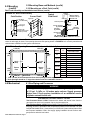
FIGURE 3A - Optional
Roof Curb
IMPORTANT: Area enclosed by the roof curb must comply
with clearance to combustible materials. If roof is constructed
of combustible materials, area within curb must be either ven-
tilated, left open, or covered with non-combustible material
which has an "R" value of at least 5.0. If area within curb is
left open, higher radiated sound levels may result.
Roof Curb Dimensions (mm)
Size 125 150, 175 200, 225 250, 300 350 400
Option CJ1 - Roof Curb for (H)RPB
A 60-5/8 60-5/8 60-5/8 60-5/8 60-5/8 60-5/8
B 24-5/16 29-13/16 35-5/16 43-9/16 49-1/16 54-1/2
C** 56-15/16 56-15/16 56-15/16 56-15/16 56-15/16 56-15/16
D** 20-9/16 26-1/16 31-9/16 39-13/16 45-5/16 50-13/16
Option CJ2 - Roof Curb with Factory-Installed Downturn Plenum
Option AQ5 or AQ8
A 84-9/16 84-9/16 84-9/16 84-9/16 84-9/16 84-9/16
B 24-5/16 29-13/16 35-5/16 43-9/16 49-1/16 54-1/2
Size 125 150, 175 200, 225 250, 300 350 400
C** 80-13/16 80-13/16 80-13/16 80-13/16 80-13/16 80-13/16
D** 20-9/16 26-1/16 31-9/16 39-13/16 45-5/16 50-13/16
E 25-7/8 31-3/8 36-7/8 45-1/8 50-5/8 56-1/8
F 99-5/32 104-21/32 110-5/32 118-7/16 123-15/16 129-7/16
Size 125 150, 175 200, 225 250, 300 350 400
Option CJ1 - Roof Curb for (H)RPB
A 1540 1540 1540 1540 1540 1540
B 618 757 897 1106 1246 1384
C** 1446 1446 1446 1446 1446 1446
D** 522 662 802 1011 1151 1291
Option CJ2 - Roof Curb with Factory-Installed
Downturn Plenum Option AQ5 or AQ8
A 2148 2148 2148 2148 2148 2148
B 618 757 897 1106 1246 1384
Size 125 150, 175 200, 225 250, 300 350 400
C** 2053 2053 2053 2053 2053 2053
D** 522 662 802 1011 1151 1291
Roof Curb Dimensions (inches)
** C and D are roof opening dimensions.
Roof Curb Assembly
and Installation
Instructions
(FIGURES 3A and 3B)
Curbs are shipped unassembled. Field assembly and mounting on the roof are the
responsibility of the installer. All required hardware necessary to complete the assem-
bly is supplied.
Before installing roof curb, verify that the size is correct for the system being
installed.
1. Position curb cross rails and curb side rails as illustrated in FIGURE 3A. Join the
corners as illustrated in the corner detail (FIGURE 3B).
2. Check the assembly for squareness. Adjust the roof curb so that the diagonal
measurements are equal within a tolerance of ± 1/8" (3mm).
3. Level the roof curb. To ensure a good weather tight seal between the curb cap and
the roof curb, the roof curb must be leveled in both directions with no twist end to
end. Shim level as required and secure curb to roof deck before proceeding with
ashing.
4. Install eld-supplied ashing.
5. Before placing the unit into position, apply furnished 1/4" x 1-1/4" foam sealant
tape to top surface of curb, making good butt joint at corners. The unit must be
sealed to the curb to prevent water leakage into the curb area due to blown rain
and capillary action.
in this section apply to all curbs. See FIGURES 3A and 3B and the curb installation
instructions below.

Form I-RPB, P/N 131782 R13, Page 8
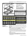
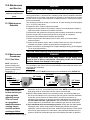
Bottom Duct Connections - The blower section and optional downturn plenum have duct anges for connection to
return air and supply air ducts. Duct opening sizes and curb spacing shown in FIGURE 4 is for currently manufactured
curbs that are available from the system manufacturer.
FIGURE 4 - Duct Opening Dimensions in Relation to Roof Curb Option - inches (mm)
1-5/8
(41)
1-5/8
(41)
1-5/8 (41)
1-5/8 (41)
1-5/8 (41)
1-5/8 (41)
19-1/2
(495)
19-1/2
(495)
H
H
G
Return
Duct
Supply
Duct
Roof Curb
1-5/8
(41)
1-5/8
(41)
• 1-5/8" (41mm) is the measurement from duct opening to inside edge of roof curb.
• Duct openings should be 1" larger than the duct size for installation clearance.
5.0 Mounting
(cont'd)
5.3 Mounting Base and Methods (cont'd)
5.3.3 Mounting on a Roof Curb (cont'd)
Sizes H
G
With Downturn Plenum,
Option AQ5 or AQ8
125
17-3/8" 38-5/8"
441mm 981mm
150, 175
22-7/8 38-5/8
581mm 981mm
200, 225
28-3/8 38-5/8
721mm 981mm
250, 300
36-5/8 38-5/8
930mm 981mm
350
42-1/8 38-5/8
1070mm 981mm
400
47-5/8 38-5/8
1210mm 981mm
6.0 Mechanical
WARNING
This appliance is equipped for a maximum gas supply pressure
of 1/2 psi, 3.4 kPa, or 14 inches water column. Supply pressure
higher than 1/2 psi requires installation of an additional service
regulator external to the unit.
PRESSURE TESTING SUPPLY PIPING
Test Pressures Above 1/2 PSI: Disconnect the heater and manual valve from the
gas supply line which is to be tested. Cap or plug the supply line.
Test Pressures Below 1/2 PSI: Before testing, close the manual valve on the heater.
6.1 Gas Piping and Pressures
Roof Curb Assembly and Installation Instructions (cont'd)
All piping must be in accordance with requirements outlined in the National Fuel Gas
Code NFPA54/ANSI Z223.1 (latest edition) or CSA-B149.1 (latest edition) Natural Gas
and Propane Installation Code. Gas supply piping installation should conform with
good practice and with local codes.
Corner Detail
Curb Section
Typical
Curb Detail
FIGURE 3B - Roof Curb Assembly

Form I-RPB, P/N 131782 R13, Page 9
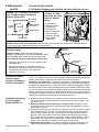
Gas Supply
Entrance
5
-3/4
(146mm)
Condensate
Weep Holes
Install the gas supply piping so that when
the union is disconnected, the supply pipe
will not interfere with the removal of the
burner rack. (The burner rack slides out of
the control side of the furnace.)
FIGURE 5 - Gas Connection Location and Requirements
Gas Connection to Single-Stage
Valve (Not Gas Supply Line Size)
RPB 125-250 300-400
Natural Gas 1/2" 3/4"
Propane 1/2" 1/2"
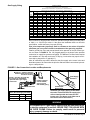
Gas Supply Sizing
Capacity of Piping
Cubic Feet per Hour based on 0.3" w.c. Pressure Drop
Specic Gravity for Natural Gas -- 0.6 (Natural Gas -- 1000 BTU/Cubic Ft)
Specic Gravity for Propane Gas -- 1.6 (Propane Gas -- 2550 BTU/Cubic Ft)
Length Diameter of Pipe
of 1/2" 3/4" 1" 1-1/4" 1-1/2" 2"
Pipe Natural Propane Natural Propane Natural Propane Natural Propane Natural Propane Natural Propane
20' 92 56 190 116 350 214 730 445 1100 671 2100 1281
30' 73 45 152 93 285 174 590 360 890 543 1650 1007
40' 63 38 130 79 245 149 500 305 760 464 1450 885
50' 56 34 115 70 215 131 440 268 670 409 1270 775
60' 50 31 105 64 195 119 400 244 610 372 1105 674
70' 46 28 96 59 180 110 370 226 560 342 1050 641
80' 43 26 90 55 170 104 350 214 530 323 990 604
90' 40 24 84 51 160 98 320 195 490 299 930 567
100' 38 23 79 48 150 92 305 186 460 281 870 531
125' 34 21 72 44 130 79 275 168 410 250 780 476
150' 31 19 64 39 120 73 250 153 380 232 710 433
175' 28 17 59 36 110 67 225 137 350 214 650 397
200' 26 16 55 34 100 61 210 128 320 195 610 372
Note: When sizing supply lines, consider possibilities of future expansion and increased requirements.
Refer to National Fuel Gas Code for additional information on line sizing.
Duct furnaces for natural gas are oriced for operation with gas having a heating value
of 1000 (+ or - 50) BTU per cubic ft. If the gas at the installation does not meet this
specication, consult the factory for proper oricing.
Pipe joint compounds (pipe dope) shall be resistant to the action of liqueed
petroleum gas or any other chemical constituents of the gas being supplied.
Install a ground joint union and manual shutoff valve upstream of the unit control sys-
tem, as shown in FIGURE 5. The 1/8" plugged tapping in the shutoff valve provides
connection for supply line pressure test gauge. The National Fuel Gas Code requires
the installation of a trap with a minimum 3" drip leg. Local codes may require a mini-
mum drip leg longer than 3" (typically 6").
After all connections are made, disconnect the pilot supply at the control valve and
bleed the system of air. Reconnect the pilot line and leak-test all connections by brush-
ing on a soap solution.
WARNING
All components of a gas supply system must be leak tested prior
to placing equipment in service. NEVER TEST FOR LEAKS WITH
AN OPEN FLAME. Failure to comply could result in personal
injury, property damage or death.

Form I-RPB, P/N 131782 R13, Page 10
6.0 Mechanical
(cont'd)
6.1 Gas Piping
and Pressures
(cont'd)
Measuring manifold gas pressure cannot be done until the heater is in operation. It is
included in the steps of the "Check-Test-Start" procedure in Paragraph 9.0. The follow-
ing warnings and instructions apply.
WARNING
Manifold gas pressure must never exceed 3.5" w.c. for natural gas
and 10" w.c. for propane gas.
For Natural Gas: When the heater leaves the factory, the combination valve is set so
that the outlet gas pressure of a single-stage valve or high re of a two-stage valve is
regulated to 3.5" w.c. Low re on a two-stage valve is set to 1.8" w.c. Inlet supply pres-
sure to the valve must be a minimum of 5" w.c. or as noted on the rating plate and a
maximum of 14" w.c. NOTE: Always check the rating plate for minimum gas sup-
ply pressure. Minimum supply pressure requirements vary based on size of burner
and the gas control option. Most units require a minimum of 5" w.c. of natural gas as
stated above, but Sizes 350 and 400 with electronic modulation require a minimum of
6" w.c. natural gas supply pressure. Sizes 300 and 350 with mechanical modulation
require 7" w.c.
For Propane: When the heater leaves the factory, the combination valve is set so that
the outlet gas pressure of a single-stage valve or high re of a two-stage valve is 10"
w.c. Low re on a two-stage valve is set to 5" w.c. Inlet pressure to the valve must be a
minimum of 11" w.c. and a maximum of 14" w.c.
Before attempting to measure or adjust manifold gas pressure, the inlet (supply) pres-
sure must be within the specied range for the gas being used both when the heater is
in operation and on standby. Incorrect inlet pressure could cause excessive manifold
gas pressure immediately or at some future time.
Manifold or Orice (Valve Outlet) Pressure Settings
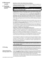
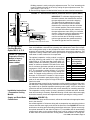
6.2 Venting
Locate power-vented furnaces so that ue discharge is not directed at fresh air inlets.
The ue discharge openings are located on the side of the furnace just above the con-
trol access panel. The position of this opening discourages recirculation of combustion
products and provides for furnace operation in all normal weather conditions.
Optional Vertical Flue
Discharge (Option CC3)
These power vented furnaces are certied with four feet of vertical pipe attached as
shown in FIGURES 6A and 6B. The distance is measured from the top of the unit to
the bottom of the vent cap. The option package includes the 5" vent cap, the adapter
assembly and the seal plate. The vent pipe and supports are eld supplied.
Optional vertical vent piping provides compliance with local codes that require either
10-ft horizontal or 4-ft vertical clearance between the ue outlet and fresh air intake of
the heating system and/or the building.
Instructions to Check Valve Outlet (Manifold) Pressure:
1) With the manual valve (on the combination valve) positioned to prevent ow to the
main burners, connect a manometer to the 1/8" pipe outlet pressure tap in the valve.
NOTE: A manometer (uid-lled gauge) is recommended rather than a spring type
gauge due to the difculty of maintaining calibration of a spring type gauge.
2) Open the valve and operate the heater. Measure the gas pressure to the manifold.
To measure the low stage pressure on units equipped with a two-stage valve, discon-
nect the wire from the "HI" terminal on the valve. (Be sure to reconnect the wire.)
Normally adjustments should not be necessary to the factory preset regulator. If adjust-
ment is necessary, set pressure to correct settings by turning the regulator screw IN
(clockwise) to increase pressure. Turn regulator screw OUT (counterclockwise) to
decrease pressure. Consult the valve manufacturer's literature provided with the fur-
nace for more detailed information.
CAUTION: DO NOT bottom out the gas valve regulator adjusting screw.
This can result in unregulated manifold pressure causing overre and
heat exchanger failure.

Form I-RPB, P/N 131782 R13, Page 11
Oval Adapter Assy,
PN/ 103025
Venter Seal Plate,
P/N 43446
FIGURE 6A - Installation of Adapter
for Optional Vertical Flue Discharge
(Option CC3, P/N 45021)
Attach the venter seal plate and oval
adapter assembly with sheetmetal screws.
Use venter seal plate as drill template.
FIGURE 6B -
Installation of
the Vent Cap
(included in the
option pkg) and
the eld-supplied
piping and
supports
6.3 Unit Inlet Air
Depending on how the unit was ordered, the blower cabinet can have a variety of
outside air and return air inlets. The cabinet end can be open requiring a eld-installed
hood , Option AS2, (See Paragraph 6.3.1), or the cabinet end can have a duct ange
(see dimensions in Paragraph 4.1, FIGURE 1). With either a hood or duct ange, the
inlet can have a damper. Dampers are available in a variety of congurations with a
variety of controls (AR Options). Options AR 6 and 7 have a 30% outside air hood and
a one-louver damper.
When ordered, a lter rack with a variety of lter options, is factory-installed in the
blower cabinet.
If the unit is ordered with an evaporative cooling module (Option AS 3, 4, 5, or 8), it is
factory-attached to the blower cabinet and is the point of entry for outside air.
Check the unit to be aware of the inlet air requirements of your installation.
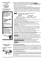
6.3.1 Field-Installed
Outside Air Hood
Outside air hood (Option AS2) is a weatherized, screened hood designed to be eld
assembled and installed around the horizontal inlet air opening of the blower cabinet.
The air hood includes factory-assembled louvers designed to help eliminate moisture
from the inlet air. Complete installation instructions are packaged with the air hood
option.
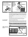
CAUTION: It is recommended that the inlet to the outside air
hood NOT be facing into the prevailing wind. Allow 14" (356mm)
minimum clearance from the bottom of the air hood to the mounting
surface.
Option AS2, 100% Outside Air Hood
NOTE: The width of the outside air hood
is the same as the width of the blower
cabinet.
FIGURE 7 - Dimensions
of Option AS2, Outside
Air Hood
RPB Size
Width of Outside Air Hood
inches mm
125 53-3/8 1356
150,175 34-1/8 867
200,225 39-5/8 1006
250,300 47-7/8 1216
350 53-3/8 1356
400 58-7/8 1495

Form I-RPB, P/N 131782 R13, Page 12
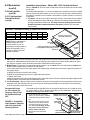
Installation Instructions - Option AS2, 100% Outside Air Hood
Refer to FIGURE 8. All screw ends except those across the bottom should be inside
the air hood.
To avoid possible damage, it is recommended that the outside air hood be installed
after the system has been placed on the roof. The air hood should be installed before
the heater is operated. Do not install the hood while the system (furnace or blower) is
in operation.
1. Top Panel - On the air inlet side of the blower cabinet, remove the factory-installed
screws attaching the blower cabinet top. Slide the air hood top panel underneath
the edge of the blower cabinet top. The edge of the air hood top panel must be
between the blower cabinet top and the end panel. Reinsert all of the sheet-
metal screws.
NOTE: Either a manufacturer
designed optional air inlet
hood as shown here or an
evaporative cooling module as
shown in Paragraph 6.3.4 is
required to ensure complete
weather resistance.
FIGURE 8 - Assembly Drawing of Option AS2 Outside Air Hood
6.3.1 Field-Installed
Outside Air Hood
(cont'd)
6.3 Unit Inlet Air
(cont'd)
6.0 Mechanical
(cont'd)
2. Side Panels - Slide the air hood right side panel into the groove in the blower cabinet end panel. Be sure that the
side panel is underneath and to the inside of the air hood top panel. Attach to the blower cabinet and the air hood
top using the required number of sheetmetal screws. Repeat with the left side panel.
3. Bottom Panel - Position the air hood bottom panel so that it is to the inside of the two side panels and above the
factory-installed support angle. Attach to the side panels.
If the bottom panel does not rest tightly against the support angle, follow these instructions to adjust the position of
the support angle:
a) Slightly loosen (do not remove the screws).
b) Slide the support angle up so that it is against the bottom panel.
c) Tighten the screws.
Attach the support angle to the air hood bottom panel. The bottom panel of the air hood and the support angle should
be tight together; do not draw with the sheetmetal screws.
4. Louver Assembly - With the intake screen toward the inside of the hood position the pre-assembled vertical louver
assembly in the inlet opening of the air hood. Using the remaining sheetmetal screws, attach the louver assembly
to the air hood side panels at the holes.
RPB Size 125 150,175 200,225 250,300 350 400
Top Panel 100227 100228 100229 100230 100231 100232
Bottom Panel 100234 100235 100236 100237 100238 100239
Louver Assy 103773 103774 103775 103776 103777 103778
Screened Air Hood
for 30% Outside Air
Opening, Part of Inlet
Air Options AR6 and
AR7
The outside air hood included in the air inlet options that have a 30% outside air open-
ing (Option AR6 or AR7) is shipped separately for eld installation. Instructions for
attaching are packaged with the air hood.
FIGURE 9 - Installation
of Air Hood on Cabinets
with 30% Outside Air
Opening Options
1. On the inlet air side of the blower
cabinet, remove the factory installed
screws attaching the blower cabinet
top.
2. Slide the air hood top ange under-
neath the lip of the blower cabinet
top and the sides into the vertical
slots. The air hood ange must be
between the blower cabinet top
and the cabinet end panel.
3. Reinsert all of the sheetmetal
screws.

Form I-RPB, P/N 131782 R13, Page 13
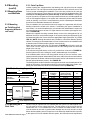
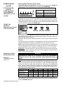
6.3.2 Filter Rack and
Filters, Option AW
Filter rack and lters are factory installed optional equipment. Refer to FIGURE 10, for
lter arrangements.
Tested in accordance with ASHRAE 52-76 Test Standard, the lters provided have the
specications shown in the table below.
Size, quantity, and pressure drops of lters for outdoor models shown below.
FIGURE 10 - Filter
Arrangements
Shaded areas are lter
blockoff plates.
Filter
Code
Filter
Size
A 16 x 20
B 20 x 20
C 16 x 25
D 20 x 25
E 25 x 25
Average Efciency and Arrestance by Filter Type
Type of Filter Average Efciency Average Arrestance
Disposable 2" Less than 20% 80%
Permanent 2" Less than 20% 64% to 67%
Pleated Disposable 2" 30% to 35% 90% to 93%
Filter Pressure Drops (" w.c.)
RPB
Size
Qty & Size
of Filters
CFM Disposable Permanent Pleated
125
(1) 20x25;
(1) 25x25
575 0.00 0.01 0.01
1000 0.01 0.03 0.04
1500 0.02 0.06 0.08
2000 0.02 0.11 0.15
2500 0.03 0.17 0.23
3000 N/A 0.24 0.33
3500 N/A 0.34 0.45
4000 N/A 0.43 N/A
150,
175
(2) 16x20;
(2) 16x25
1175 0.01 0.03 0.03
1500 0.01 0.06 0.05
2000 0.02 0.08 0.09
2500 0.03 0.14 0.14
3000 0.04 0.20 0.23
3500 0.05 0.28 0.27
4000 0.07 0.36 0.36
4500 N/A 0.45 0.45
5000 N/A 0.54 0.56
200,
225
(1) 16x20;
(1) 16x25;
(1) 20x20;
(1) 20x25
1550 0.01 0.04 0.04
2000 0.01 0.07 0.07
2500 0.02 0.11 0.11
3000 0.03 0.16 0.16
3500 0.04 0.22 0.21
4000 0.05 0.28 0.27
4500 0.06 0.36 0.35
5000 N/A 0.44 0.43
5400 N/A 0.52 0.50
250,
300
(1) 20x20;
(3) 20x25
1950 0.02 0.05 0.05
2500 0.03 0.08 0.08
3000 0.04 0.12 0.11
3500 0.05 0.16 0.15
4000 0.07 0.21 0.20
4500 0.09 0.26 0.25
5000 0.11 0.32 0.31
5500 N/A 0.39 0.37
6000 N/A 0.46 0.44
6500 N/A 0.54 0.52
350
(2) 16x25;
(3) 20x25
2750 0.03 0.08 0.08
3500 0.04 0.13 0.13
4000 0.06 0.17 0.17
4500 0.07 0.21 0.22
5000 0.09 0.26 0.27
5500 0.10 0.32 0.33
6000 0.12 0.38 0.39
6500 N/A 0.44 0.46
7000 N/A 0.51 0.53
3100 0.04 0.08 0.08
400
(1) 16x20;
(1) 16x25;
(2) 20x20;
(2) 20x25
3500 0.06 0.11 0.11
4000 0.07 0.14 0.14
4500 0.09 0.18 0.18
5000 0.12 0.22 0.22
5500 0.14 0.27 0.27
6000 0.17 0.32 0.32
6500 0.20 0.38 0.37
7000 0.23 0.44 0.43
7400 N/A 0.49 0.48
Optional Dirty Filter Switch
The optional dirty lter pressure switch is used to provide warning to the
user by energizing an indicator light on an optional remote console. The
light indicates that the lters are in need of cleaning or changing. The
adjustable, single-pole/normally open differential switch closes when an
increase in pressure differential above the setpoint, is sensed across the
lter bank.
This switch is located in the furnace section. See page 28, FIGURE 29
Item 17. After the unit is started, before continuous operation, the dirty lter
switch must be set.
Instructions for Setting Switch
With clean lters in place, blower doors closed, and blower in operation,
decrease the pressure setting by adjusting the setscrew on the switch
clockwise until the lter light is energized or the screw is bottomed out.
At that point, adjust the set screw three full turns counterclockwise or until
the screw is top-ended. At that setpoint the lter light will be activated at
approximately 50% lter blockage.
FIGURE 11 - Dirty Filter Switch
Setscrew (on front of switch)
must be manually adjusted
after the system is in operation.
Negative pressure connection is toward the "front or top"
of the switch (senses blower side of lters)
Positive pressure connection is
toward the "back or bottom" of the
switch (senses air inlet side of lters)

Form I-RPB, P/N 131782 R13, Page 14
6.3 Unit Inlet Air (cont'd)
6.0 Mechanical
(cont'd)
6.3.3 Optional Dampers and Controls (See Wiring Diagram on unit.)
NOTE: Damper controls are illustrated in
FIGURE 12A and 12B. These illustrations are intended to show location only of various air control accessories
and do not represent suggested combinations of accessories.
Furnace
Section
Blower
Blower Cabinet
30% Outside
Air Damper
30% Outside
Air Hood
Damper Motor
Return Air
FIGURE 12A - Location of Controls for
30% Outside Air Hood and Damper
Options (AR6 or AR7)
FIGURE 12B - Control
Locations for 100%
Outside Air and 100%
Return Air Damper
Options
1 Damper Motor
2 Return Air Damper
3 Potentiometer
4 Potentiometer
5 Mixed Air Controller
6 Warmup Control
7 Outside Air Damper
8 Damper Motor
Transformer
Damper Linkage - When units are equipped with
dampers, the dampers are closed during shipment. When
there are both return air and outside air dampers, the
return damper linkage must be adjusted prior to use.
1. Loosen the set screw on the return air damper rod at
the damper arm.
2. Manually open the return air dampers. While the
dampers are opening, the damper rod and arm will
automatically move to their correct positions.
3. Tighten the set screw.
Outside Air
Damper
CLOSED
Return Air
Damper OPEN
Rod for Outside
Air Damper
Setscrew
Outside Air
Damper Arm
Return
Air
Damper
Arm
Rod for Return
Air Damper
Damper
Motor
FIGURE 12C - Example of Outside Air and Return Air
Damper Linkage
Pressure Null Switch
(Used to control
Outside Air Dampers in
Inlet Air Option AR23)
The pressure null switch used in Option AR23 is a Dwyer #1640-0 with a range of .01-
.20" w.c. It is shipped separately for eld installation. Refer to the following paragraphs
and the manufacturer's installation instructions included with the switch.
Description and Application - The pressure null switch is a diaphragm operated dif-
ferential pressure switch used in makeup air applications to control building pressure.
It maintains a selected positive or negative pressure setpoint by changing the amount
of outside air being introduced to the building through the modulating outside air damp-
ers. As more pressure is required in the building, the pressure null switch activates the
damper motor driving the outside air damper towards the full open position and the
recirculated air damper towards the closed position. Conversely, as less pressure is
required, the switch drives the dampers in the opposite direction.
1. Select an indoor location free from excessive vibration where oil or water will not
drip onto the switch and where ambient temperature will be within a range of -30°F
(dry air) to 110°F.
2. Mount the switch with the diaphragm in a vertical plane. The switch is posi-
tion sensitive and is calibrated to operate properly when the diaphragm is vertical.
Mount switch securely.
3. Connect the pressure taps on the top of the switch to sources of air pressure differ-
ential. Metal tubing with 1/4" O.D. is recommended, but any tubing system which
will not unduly restrict the air ow may be used. To maintain a positive building
pressure, vent the low pressure tap to the outdoors and allow the high pressure
tap to monitor building pressure. To maintain a negative building pressure, reverse
the functions of the high and low pressure taps. In either case, be sure that the
outdoor vent is protected from the wind and screened from insects.
4. Adjustment of the Switch - The "HIGH" actuation point of the null switch is indi-
cated on a calibrated scale secured to the transparent range screw enclosure.
Installation Instructions
for Pressure Null
Switch (FIGURE 13)

Form I-RPB, P/N 131782 R13, Page 15
FIGURE 13 - Pressure Null Switch (used with Inlet Air Option AR23)
IMPORTANT: To eliminate shipping damage to
the switch contacts, the manufacturer reduced
the span adjustment to zero before shipping.
The span should be adjusted prior to using
the switch. (If the switch has been installed,
disconnect the vent tube so that the null switch
is in a neutral position.) Remove the electrical
box cover and while observing the contacts, turn
the span adjustment screw slowly in a clockwise
direction. Continue turning the adjustment screw
until you are able to see gaps between the
common and both the low and high contacts. A
minimum gap provides the greatest sensitivity.
The wider the gap the lower the sensitivity.
Building pressure is set by turning the adjustment screw. The "Low" actuation point
is set by adjusting the span of the null by turning the span adjustment screw. The
span range is .01 to .03" w.c.
5. See the wiring diagram included with the furnace to make electrical connections.
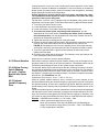
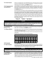
6.3.4 Evaporative
Cooling Module,
Option AS 3, 4, 5, 8
General - Evaporative cooling provides excellent comfort cooling at low initial equip-
ment and installation costs and low operating and maintenance costs. Direct evapo-
rative cooling works solely on the principle that water in direct contact with a moving
airstream will eventually evaporate if the droplets have long enough exposure. This
evaporative cooling module uses wetted rigid cellulose or rigid glass ber media to
retain water in order to allow time for evaporation.
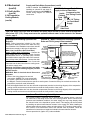
FIGURE 14 - Optional
Evaporative Cooling
Module is factory-
installed on the
blower cabinet
The optional evaporative cooling module is equipped
with high efciency pad media of 12" rigid cellulose
(Option AS4) or 12" rigid glass ber (Option AS8). 12"
media provides 90% efciency. Efciency values are
stated at maximum allowable CFM without the addi-
tion of a moisture elimination pad with an inlet dry bulb
temperature of 95°F and inlet wet bulb temperature of
65°F. The evaporative cooling efciency is a function
of inlet temperature and of face velocity through the
media. The stated cooling efciency will rise with the
decrease of CFM and the increase of inlet tempera-
ture. Moisture elimination pads (Option ASA1) may be
used on all units but are required on high CFM units as
listed in the table.
The standard water controls for the evaporative cooling module include the oat valve,
the oat switch, and pump assembly illustrated in the following paragraphs. If the cool-
ing module has an optional AquaSaver
metering water system, it will not have these
controls but will have a solenoid valve with a timer assembly for controlling water ow.
RPB
Size
Moisture Elimina-
tion Pad Required
on Evaporative
Cooling Module
125 2601 - 3800 CFM
150 3201 - 4700 CFM
175 3201 - 5000 CFM
200 3701 - 5100 CFM
225 3701 - 5150 CFM
250 4501 - 5800 CFM
300 4501 - 6300 CFM
350 5101 - 6800 CFM
400 5601 - 7100 CFM
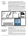
Supply and Drain Water
Connections
Installation Instructions
- Evaporative Cooling
Module
The evaporative cooling module is factory assembled, installed and wired. No addi-
tional roof mounting is necessary. Read the following to eld connect the water supply
and make necessary checks and adjustments before operating the cooling module.
Float Valve (FIGURE 15)
In a module with pump and oat controls, a oat valve maintains the appropriate water
level in the reservoir.
Use a eld-supplied 1/4" diameter tubing with a compression nut and tubing ferrule to
connect the fresh water supply to the inlet of the oat valve. See FIGURE 15. Place nut
and ferrule over tubing and insert tubing into the oat valve stem. Tighten nut securely.
An optional automatic ll and drain kit (Option CT) is available that will automatically
release supply water to the cooling module when a call for cooling is made and drain
all water from the reservoir when the cooling switch is deactivated or a cooling ther-

Form I-RPB, P/N 131782 R13, Page 16
6.3 Unit Inlet Air
(cont'd)
6.0 Mechanical
(cont'd)
FIGURE 15 - Connect Fresh Water
Supply to Inlet of Float Valve
Simulates
Side Panel
Use 1/4" Tubing
for Fresh Water
Supply
Compression Nut
and Tubing Ferrule
(Inside
Cabinet)
Float
Valve Rod
Instructions for Installing Optional Fill &
Drain Kit
NOTE: Follow instructions included in the valve
packages for attaching valves to the water line only.
The remainder of the installation instructions with the
valves does not apply to this type of application.
Water Line Connections (See illustration):
Supply (3-Way Valve) Connections - Connect the
water supply line to "B" (normally closed). Connect
the water drain line to "A" (normally open). Connect
the middle outlet to supply the water to the reservoir.
Drain (2-Way Valve) Connections - Connect the drain
pipe from the reservoir to the valve inlet. Connect the
outlet side into the drain lines from the cooling reser-
voir and the supply valve.
Electrical Connections (requires black and white
14-gauge wire) Refer to Wiring Diagram provided
with the furnace:
WARNING: Risk of electrical shock. Disconnect
the power.
1. Refer to the wiring diagram for terminal
connections. (NOTE: If kit is not ordered with
the system, connections will not be shown on
FIGURE 16 - Water Connections including Optional
Drain and Fill Kit (pump & oat controls)
the diagram. Terminal connections are specic to each system. Contact the factory for terminal connections. Be
prepared to provide all model information.)
2. Run eld-supplied black wire from the electrical compartment (terminal on the wiring diagram) of the evaporative
cooling module and connect to the black wire on both the 3-way and the 2-way valve.
3. Run eld-supplied white wire from the electrical compartment (terminal on the wiring diagram) of the evaporative
cooling module and connect to the white wire on both the 3-way and the 2-way valve.
mostat is satised. See FIGURE 16. If
installing an optional ll and drain kit,
follow the instructions with FIGURE 16.
Consult wiring diagram for electrical
connections.
6.3.4 Evaporative
Cooling Module,
(cont'd)
AquaSaver Timed Metering Control System
If the cooling module is equipped with an optional timed metering system, connect a
1/2" water line to the tting on the side of the cooling module. Due to various water
pressures and installation conditions, the water supply line may bang abruptly when
the solenoid valve in the AquaSaver system closes. This banging can be minimized
by installing an optional water hammer arrestor in the supply line. When installing an
optional water hammer arrestor, select an indoor (above 32°F) location, either horizon-
tal or vertical, in line with and as close to the solenoid valve as possible. Follow the
manufacturer's instructions to install and maintain the water hammer arrestor.
A freeze protection kit (Option CT5) is also available.
CAUTION: Water reservoir must be drained and pump motor turned off when outside temperature
falls below 32°F (0°C). Pump must never be operated without water in the reservoir. See Hazard
Levels, page 2.
Supply and Drain Water Connections (cont'd)

Form I-RPB, P/N 131782 R13, Page 17
Bleed Line Connection (Does not apply to module with optional timed metering sys-
tem.) - Shipped in the evaporative cooling module bottom pan, nd a 1/4" I.D. x 1/2"
N.P.T. nylon bleed line tting (hose barb). Thread the tting into the female adapter
located opposite the pump/inlet side of the water distribution line. The hose barb will
protrude from the side of the cabinet (See FIGURE 17). Attach a 1/4" I.D. hose to the
barb and run the hose to the nearest drain.
Discharging a quantity of water by "bleed off" will limit the concentration of undesirable
minerals in the water being circulated through the cooling module. Minerals buildup
because evaporation only releases "pure water vapor" causing the concentration of
contaminants in the water to increase as the evaporation process continues. The min-
erals accumulate on the media, in the water lines, on the pump, and in the reservoir.
Adequate bleed off is important to maintaining an efciently operating evaporative
cooling system.
Install the hose barb
and attach bleed line.
FIGURE 17 - Bleed Line
Connection
Filling and Adjusting the Water Level in the Reservoir
Float and Pump Control System - Turn on the water supply. Check for good ow.
When the oat valve (FIGURE 15) shuts off the water supply, measure the water
depth. The depth of the water should be approximately 3". It may be necessary to
adjust the oat valve to obtain the proper water level or to free the oat valve from
obstructions. To adjust the oat valve, simply bend the rod upward to raise the water
level or downward to decrease the water level.
Adjusting Water Flow Over Pads
Proper water ow over the evaporative cooling media is critical to extend the life and
maintain the efciency of the pads. Follow the instructions to adjust water ow.
CAUTION: Do not ood the media pads with extreme quantities of water
for long periods as this will cause premature breakdown of the media.
An even ow from top to bottom of the media with the least amount of
water is all that is required to assure maximum efciency and media life
span. More water does not provide more evaporation or more cooling.
FIGURE 18 -
Disconnect the power
and use ball valve to
adjust water ow.
Ball
Valve
All Evaporative Cooling Modules - A manual water shutoff valve should be installed upstream of the cooling module
inlet, at a convenient non-freezing location, to allow the water supply to be turned on and off. If necessary, install a bleed
line between the manual valve and the cooling module to allow drainage of the line between the shutoff valve and the
cooling module.
All cooling modules are equipped with an overow and drain tting. The ttings are in the cabinet bottom and come
complete with a lock nut and a sealing gasket. Check these ttings for tightness before installing the overow and drain
piping. The drain and overow tting will accommodate a 3/4" garden hose thread and is tapped with a 1/2" female pipe
thread for iron pipe.
WARNING
Adjust ball valve only when the power is disconnected from the system. Failure to do so
can cause electrical shock, personal injury or death.
Float and Pump Control System - Using the ball valve, located in the middle of the
length of hose running from the pump to the distribution line inlet (FIGURE 18), adjust
the valve handle to allow the ow to completely dampen the media pads from top to
bottom.
Operate the unit watching the water ow. After 15 minutes with the blower in operation,
the water should have completely dampened the pads but should not be owing off the
entering side of the media. If water is owing off the entering side of the media, turn the
system off, disconnect the power, and reduce the entering water ow.
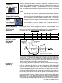
AquaSaver Timed Metering Control System - NOTE: Water ow and pad wetting
time should be adjusted at maximum airow and wet bulb depression to assure com-
plete wetting of the media at the extreme operating conditions.
In addition to adjusting water ow, the timing of the water on/off cycle can be adjusted.
Adjustments are correct when 1) the water rises from the holes in the sprinkler pipe
(See FIGURE 19A) consistently along the entire pipe length, 2) the media pads wet
evenly after a few "ON" cycles (no dry spots or dry streaks), and 3) a slight amount of
excess water collects at the drain at the completion of the "ON" cycle.

Form I-RPB, P/N 131782 R13, Page 18
6.3 Unit Inlet Air
(cont'd)
6.0 Mechanical
(cont'd)
FIGURE 19A - Adjust Water Flow with the Ball Valve in FIGURE 18
Sprinkler Pipe
Pad
Height
A=Water Rise from
PVC Sprinkler Pipe
24" (610mm) 1/8" to 1/2" (3 to 13mm)
48" (1219mm) 1/4" to 1/2" (6 to 13mm)
FIGURE 19B -
AquaSaver
Microprocessor Control
in the Junction Box
J2
1 2 3 4 1 2 3 4 1 2 3 4 1 2 3 4
S
M
L
12-36
(305-914mm)
Media Height
37-48
(940-1219mm)
Media Height
49-72
(1245-1829mm)
Media Height
2) AquaSaver Timer Adjustment - At any given temperature, the media pads should
completely wet from top to bottom during the ON cycle. The microprocessor has three
preset timing settings based on media size. The appropriate setting is selected by
changing the position of the suitcase jumper at J2 on the microprocessor. Remove the
cover and check the setting (See FIGURE 19B).
If the jumper is at the appropriate location for the media, replace the cover. If the
jumper needs to be moved, move it to the appropriate setting. The setting will go into
effect when the power is restored.
Check the "ON" timing; the media pads should be wet from top to bottom during the
ON cycle.
If the preset timing is not suitable for the application, follow the instructions supplied
with the microprocessor to change the calibration of the "On" and/or "Off" cycle.
NOTE: Prior to 2003 the AquaSaver timed cycle was controlled by a mechanical timer.
Turn the adjustment screw clockwise to increase the ON time or counterclockwise to
decrease the ON time. One complete turn will adjust the cycle by 12 to 14 seconds.
All Modules - Check the reservoir for any water leaks. The reservoir was water tested,
but if any small leaks are present, drain the reservoir and apply a waterproof silicone
sealer around corners and welds.
Reference:
Troubleshooting Guide
on page 20.
1) AquaSaver Water Flow Adjustment - Using the ball valve illustrated in FIGURE 18,
adjust the water ow depending on the pad height. See FIGURE 19A.
6.3.4 Evaporative
Cooling Module,
Option AS 3, 4, 5, 8
(cont'd
)
Evaporative Cooling
Module Maintenance
Adjusting Water Flow Over Pads (cont'd)
WARNING
Disconnect all power to the unit before doing any maintenance.
Failure to do so can cause electrical shock, personal injury or
death.
Media - Over time, excessive amounts of mineral deposits may begin to build up on the
media. Annually, scale and dirt should be washed off the entering surface of the media.
Remove the pad retainers and screen (See Steps 1-3 and 6-8 of Media Replacement
Instructions). Clean the media using a garden hose, mild cleaner, and a soft bristled
brush. When the media becomes too clogged with mineral deposits and dirt that it
cannot be cleaned, the pads should be replaced. The average pad life expectancy is
approximately three cooling seasons.
RPB Size 125 150, 175 200, 225 250, 300 350 400
12" Media Pads - dimen-
sions and (Qty)
(2) 24x12 (3) 24x12 (4) 24x12
(1) 24x2-3/8 (1) 24x7-7/8 (1) 24x1-3/8 (1) 24x9-5/8 (1) 24x2-7/8 (1) 24x8-5/8
Cellulose Fiber Media
Replacement P/N's & (Qty)
(2) 106021;
(1) 106022
(2) 106021;
(1) 106023
(3) 106021;
(1) 106024
(3) 106021;
(1) 106025
(4) 106021;
(1) 106026
(4) 106021;
(1) 106027
Glass Fiber Media
Replacement P/N's & (Qty)
(2) 106029;
(1) 106030
(2) 106029;
(1) 106031
(3) 106029;
(1) 106032
(3) 106029;
(1) 106033
(4) 106029;
(1) 106034
(4) 106029;
(1) 106035
Select the correct replacement part numbers and order replacement media pads from
your distributor. Follow the instructions that follow and remove and replace pads as
shown in FIGURES 20 and 21.

Form I-RPB, P/N 131782 R13, Page 19
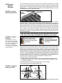
FIGURE 20 - Removal and Replacement of
Evaporative Cooling Module Media
FIGURE 21 -
Media must
be installed
with 45°
angle sloping
downward
toward the
incoming
outside air.
IMPORTANT: The media is made up of two different
sheets of cooling material. Each sheet has its own
unique angle. When replacing the cooling media,
BE CERTAIN that the 45° angle slopes downward
toward the incoming outside air. If the media is not
installed properly, water blowoff from the media
pads will occur.
Instructions for
Replacing Media Pads
1. Remove the three sheetmetal screws that hold the top pad retainer. Release the
top pad retainer from the cooling module.
2. Remove the three sheetmetal screws that hold the bottom pad retainer. Release
the bottom pad retainer from the cooling module.
3. Disengage the inlet screen from media pads and remove.
4. Slide all media pads horizontally away from the cooling module until clear of
bottom reservoir pan. Dispose of properly.
5. Slide media pads over both support rails until back stop is encountered. Media
must be placed as shown in FIGURE 21.
6. Center screen on the incoming air side of the media.
7. Replace the bottom pad retainer by securing the retainer between the pad and the
reservoir pan. Fasten with the three sheetmetal screws removed in Step 2.
8. Replace the top pad retainer by securing the retainer between the pad and top of
the cooling module. Fasten with the three sheetmetal screws removed in Step 1.
Water Feed and
Distribution Line
Annually, the water supply line and the water distribution line (either PVC pipe or water
sock) should be ushed of debris and contaminants.
1. Remove the media pads.
2. Remove the water feed line from the downstream side of the ball valve and
unscrew the water bleed line barbed hose tting.
3. Force a fresh water supply through the water inlet hose and thoroughly ush the
distribution line.
4. Reassemble being careful to install media with air ow direction as shown in
FIGURE 21.
Water Pump and Inlet
Basket Screen (Does
not apply to module with
optional timed metering sys-
tem.) - Annually, the pump
and inlet basket screen
should be removed, disas-
sembled, and cleaned.
WARNING
Do not expose pump motor or any part of the electrical box to
water. Evaporative cooling pump is NOT submersible.
1. Disconnect the power supply to the unit.
2. Remove the service panel and the junction box door. Disconnect the two-line
voltage power supply wires from the terminal block inside the junction box.
3. Disconnect the water feed line hose from the upstream side of the ball valve.
4. Unscrew the four sheetmetal screws holding the junction box to the cooling
module. Remove the junction box-pump-oat switch assembly (See FIGURE 22).
5. Dislodge the inlet basket screen from the pump and clean any buildup of debris
and dirt. Carefully remove the base cover plate from the bottom of the pump.
Using a mild soap solution, wash all deposits from the inside of the pump and
remove all debris from the impeller.
6. Reassemble the pump. Replace the parts in exact reverse order, being careful that
everything is returned to its proper position.

Form I-RPB, P/N 131782 R13, Page 20
6.3.4 Evaporative Cooling Module, Option AS 3, 4, 5, 8 (cont'd)
6.3 Unit Inlet Air (cont'd)
6.0 Mechanical
(cont'd)
WARNING
Disconnect the power before servicing the cooling module. Failure to
do so can cause electrical shock, personal injury or death.
Troubleshooting
Evap Cooler
Problem Probable Cause Remedy
Pump does not run.
Unit is calling for cooling
(control switch is in cooling
position) and reservoir is full.
1. Electrical connections 1. Verify all electrical connections. See Wiring Diagram.
2. Electric oat switch on pump 2. Check position of the actuators on the electric oat switch.
3. Dirty pump 3. Clean pump. See FIGURE 22.
4. Defective pump 4. Replace pump.
Required water level (3")
not maintained (pump
and oat control system)
1. Float valve 1. Adjust oat valve. See Filling and Adjusting Water Level.
2. Optional drain and ll valves 2. Check valve for proper operation. See FIGURE 16.
3. Incorrect overow pipe nipple - should be 3-1/2" 3. Replace pipe nipple.
4. Drain leaking 4. Tighten drain plug.
Water running off of
media pads
1. Excessive water ow 1. See adjust water ow instructions.
2. Media needs cleaned or replaced. 2. Clean or replace media pads.
Water not distributing
evenly
1. Distribution line clogged 1. Flush distribution line. See Evap Cooling Module Maintenance.
2. Holes in distribution line turned 2. Check position of distribution line. Holes should be spraying
upward. If not positioned with holes up, adjust position of line.
3. Incorrect voltage to pump 3. Check voltage at pump terminal in cooling module junction box.
Media pads becoming
clogged & discolored
(scale/salt deposits) and/
or rapid deterioration of
the oat switch
1. Bleed off line clogged or inadequate bleed off
(pump and oat control system)
1. Clean bleed line (See FIGURE 17). A uniform build-up of
minerals on the entering air face of the media indicates insufcient
bleed off. Increase the rate until the mineral deposits dissipate.
2. Excessive water ow 2. See Adjusting Water Flow.
Water blowoff from
media pads
1. Media pads installed incorrectly 1. Install media pads correctly. See Cooling Module Maintenance.
2. Requires moisture elimination pad (over 600 FPM) 2. Install moisture elimination pad. Consult factory.
3. Water level not 3 inches (pump and oat control ) 3. See second problem listed above (Required water level)
6.4 Supply Air
Discharge
6.4.1. Duct
Connections
Requirements & Suggestions for Connecting and Installing Ducts
•
Type of Ductwork - The type of duct installation to be used depends in part on the
type of construction of the roof (whether wood joist, steelbar joist, steel truss, pre-
cast concrete) and the ceiling (whether hung, ush, etc.).
• Ductwork Material - Rectangular duct should be constructed of not lighter than
No. 26 U.S. gauge galvanized iron or No. 24 B & S gauge aluminum.
• Ductwork Structure - All duct sections 24 inches or wider, and over 48 inches
in length, should be cross broken on top and bottom and should have standing
seams or angle-iron braces. Joints should be S and drive strip, or locked.
• Through Masonry Walls - No warm air duct should come in contact with masonry
walls. Insulate around all air duct through masonry walls with not less than 1/2" (1"
is recommended) of insulation.
• Through Unheated Space - Insulate all exposed warm air ducts passing through
an unheated space with at least 1/2" (1" is recommended) of insulation.
• Duct Supports - Suspend all ducts securely from adjacent buildings members. Do
not support ducts from unit duct connections.
System has either a horizontal or vertical discharge air opening with a duct ange.
If the discharge outlet is vertical, the system was ordered with either a factory-installed
downturn plenum (AQ Option).
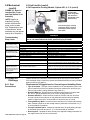
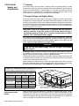
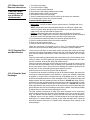
Pump
Inside View of the
Junction Box
(Note: Only 208V
unit will have a
transformer in the
junction box.)
Float
Switch
Pump
Motor
To clean the pump, carefully
remove the mesh screening
(or basket) and the snap-on
cover plate.
FIGURE 22 - Remove
Junction Box, Pump
and Float Switch as an
Assembly
(NOTE: Applies to
evaporative cooling
module with oat and
pump control system
only. Depending on date
of manufacture, actual
assembly may not appear
exactly as in the photo.)
Page is loading ...
Page is loading ...
Page is loading ...
Page is loading ...
Page is loading ...
Page is loading ...
Page is loading ...
Page is loading ...
Page is loading ...
Page is loading ...
Page is loading ...
Page is loading ...
Page is loading ...
Page is loading ...
Page is loading ...
Page is loading ...
Page is loading ...
Page is loading ...
Page is loading ...
Page is loading ...
-
 1
1
-
 2
2
-
 3
3
-
 4
4
-
 5
5
-
 6
6
-
 7
7
-
 8
8
-
 9
9
-
 10
10
-
 11
11
-
 12
12
-
 13
13
-
 14
14
-
 15
15
-
 16
16
-
 17
17
-
 18
18
-
 19
19
-
 20
20
-
 21
21
-
 22
22
-
 23
23
-
 24
24
-
 25
25
-
 26
26
-
 27
27
-
 28
28
-
 29
29
-
 30
30
-
 31
31
-
 32
32
-
 33
33
-
 34
34
-
 35
35
-
 36
36
-
 37
37
-
 38
38
-
 39
39
-
 40
40


Reznor RPB Installation guide
- Category
- Split-system air conditioners
- Type
- Installation guide
Ask a question and I''ll find the answer in the document
Finding information in a document is now easier with AI
Related papers
Other documents
-
Broan Blower Baffle for E2 Installation guide
-
Wing Enterprises IOMWDF-1 User manual
-
Applied Air Camera Lens SDRIOM-2 User manual
-
Goodmans CPG SERIES User manual
-
GOODMAN Commercial Heating and Cooling Gas Unit CPG SERIES User manual
-
Daikin DCG0601404BXXX Installation guide
-
Daikin DSG0480903BXXX Installation guide
-
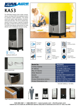 KuulAire PACKA53 Installation guide
-
 GOODMAN CPG SERIES User manual
-
Hastings COUNTERFLO CF SERIES Installation and Service Manual

