Page is loading ...

Contents
Introduction to VLT 2800
4
Software version 4
High voltage warning 5
These rules concern your safety 5
Warning against unintended start 5
Technology 6
CE labelling 8
Motor coils 12
Ordering numbers for VLT 2800 200-240 V 16
Ordering numbers for VLT 2800 380-480V 17
PC Software tools 21
Accessories for the VLT 2800 22
Control unit 29
Manual initialisation 29
Hand Auto 30
Automatic motor tuning 31
The LCP 2 Control unit, option 32
Parameter selection 35
Installation
37
Mechanical dimensions 37
Mechanical installation 41
General information about electrical installation 42
EMC-correct electrical installation 44
Earthing of screened/armoured control cables 46
Diagram 47
Electrical installation 48
Safety clamp 50
Pre-fuses 50
Mains connection 50
Motor connection 51
RFI switch 51
Direction of motor rotation 51
Parallel connection of motors 52
Motor cables 52
Motor thermal protection 53
Brake connection 53
Earth connection 53
Load sharing 54
Tightening Torque, Power Terminals 54
Control of mechanical brake 54
Access to control terminals 54
Electrical installation, control cables 55
Tightening torques, control cables 56
Electrical installation, control terminals 56
Relay connection 56
VLT Software Dialog 56
VLT
®
2800 Series
MG.27.E3.02 - VLT
®
is a registered Danfoss trademark 1

Connection examples 57
Use of internal PID-controller - closed loop process control 59
Programming
61
Operation & Display 61
Setup configuration 62
Load and Motor 69
DC Braking 74
References & Limits 80
Handling of references 81
Reference function 84
Inputs and outputs 88
Special functions 98
PID functions 101
Handling of feedback 102
Enhanced Sleep Mode 110
Serial communication for VLT 2800 115
Control Word according to FC protocol 119
Status Word according to FC Profile 121
Control word according to Fieldbus Profile 122
Status word according to Profidrive protocol 123
Serial communication 126
Technical functions 134
All about VLT 2800
139
Special conditions 139
Galvanic Isolation (PELV) 139
Earth leakage currentand RCD relays 139
Extreme operating conditions 139
dU/dt on motor 140
Switching on the input 140
Peak voltage on motor 140
Acoustic noise 141
Temperature-dependent switch frequency 142
Derating for air pressure 142
Derating for running at low speed 142
Derating for long motor cables 142
Derating for high switching frequency - VLT 2800 142
Vibration and shock 143
Air humidity 143
UL Standard 143
Efficiency 143
Mains supply interference/harmonics 144
Power factor 144
Generic EMC standards/product standards 145
EMC emission 145
EMC Immunity 146
Harmonic Current Emission 147
Aggressive environments 147
VLT
®
2800 Series
2 MG.27.E3.02 - VLT
®
is a registered Danfoss trademark

Display readout 149
Warnings/alarm messages 149
Warning words, extended status words and Alarmwords 153
General technical data 154
Technical data, mains supply 1 x 220 - 240 V/3 x 200-240V 159
Technical data, mains supply 3 x 380 - 480 V 160
Available literature 161
Supplied with the unit 161
Index
169
VLT
®
2800 Series
MG.27.E3.02 - VLT
®
is a registered Danfoss trademark 3

VLT 2800
Design Guide
Software version: 3.1x
This Design Guide can be used for all VLT 2800 Series frequency converters with software version 3.1x.
The software version number can be seen from parameter 640.
NB!
This symbol indicates something that
should be noted by the reader.
Indicates a general warning.
This symbol indicates a warning of high
voltage.
VLT
®
2800 Series
4 MG.27.E3.02 - VLT
®
is a registered Danfoss trademark

High voltage warning
The voltage of the frequency converter is
dangerous whenever the converter is con-
nected to mains. Incorrect fitting of the
motor or frequency converter may cause
damage to the equipment, serious injury
or death. Consequently, it is essential to
comply with the instructions in this manual
as well as local and national rules and
safety regulations.
The Protective Extra Low Voltage (PELV)
requirements stated in IEC 61800-5-1 are
not fulfilled at altitudes above 2000 m
(6562 ft.). For 200V frequency converters
the requirements are not fulfilled at alti-
tudes above 5000 m (16 404 ft.). Please
contact Danfoss Drives for further infor-
mation.
These rules concern your safety
1. The frequency converter must be disconnec-
ted from the mains if repair work is to be
carried out. Check that the mains supply has
been disconnected and that the prescribed
time has passed before removing motor and
mains plugs.
2. The [STOP/RESET] key on the control panel
of the frequency converter
does not discon-
nect the equipment from mains and is thus
not to be used as a safety switch.
3. The unit must be properly connected to the
earth, the user must be protected against the
supply voltage and the motor must be pro-
tected against overloading pursuant to pre-
vailing national and local regulations.
4. The earth leakage currents are higher than
3.5 mA.
5. Protection against motor overload is not in-
cluded in the factory setting. If this function is
required, set parameter 128 Motor thermal
protection to data value ETR trip or data value
ETR warning. For the North American market:
The ETR functions provide overload protec-
tion of the motor, class 20, in accordance with
NEC.
6. Do
not remove the plugs for the motor - and
mains supply while the frequency converter
is connected to mains. Check that the mains
supply has been disconnected and that the
prescribed time has passed before removing
motor and mains plugs.
7. Note that the frequency converter has more
voltage inputs than L1, L2 and L3 when the
DC bus terminals are used. Check that all
voltage inputs are disconnected and that the
prescribed time has passed before repair
work is commenced.
Warning against unintended start
1. The motor can be brought to a stop by means
of digital commands, bus commands, refer-
ences or a local stop, while the frequency
converter is connected to mains. If personal
safety considerations make it necessary to
ensure that no unintended start occurs,
these
stop functions are not sufficient.
2. While parameters are being changed, the
motor may start. Consequently,
the stop key
[STOP/RESET] must always be activated,
following which data can be modified.
3. A motor that has been stopped may start if
faults occur in the electronics of the frequen-
cy converter, or if a temporary overload or a
fault in the supply mains or the motor con-
nection ceases.
Use on isolated mains
See section RFI Switch regarding use on isolated
mains.
It is important to follow the recommendations regard-
ing installation on IT-mains, since sufficient protection
of the complete installation must be observed. Not tak-
ing care using relevant monitoring devices for IT-
mains may result in damage.
VLT
®
2800 Series
MG.27.E3.02 - VLT
®
is a registered Danfoss trademark 5
Introduction to VLT 2800

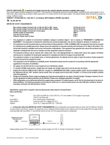
Technology
Control principle
A frequency converter rectifies AC voltage from the
mains supply into DC voltage, following which it
changes this voltage to an AC voltage with variable
amplitude and frequency.
The motor thus receives a variable voltage and fre-
quency, which enables infinitely variable speed control
of three-phase, standard AC motors.
1. Mains voltage
1 x 220 - 240 V AC, 50 / 60 Hz
3 x 200 - 240 V AC, 50 / 60 Hz
3 x 380 - 480 V AC, 50 / 60 Hz
2. Rectifier
Three-phase rectifier bridge which rectifies AC voltage
into DC voltage.
3. Intermediate circuit
DC voltage 2 x mains voltage [V].
4. Intermediate circuit coils
Evens out the intermediate circuit current and limits the
load on mains and components (mains transformer,
cables, fuses and contactors).
5. Intermediate circuit condenser
Evens out the intermediate circuit voltage.
6. Inverter
Converts DC voltage into a variable AC voltage with a
variable frequency.
7. Motor voltage
Variable AC voltage depending on supply voltage.
Variable frequency: 0.2 - 132 / 1 - 1000 Hz.
8. Control card
Here is the computer that controls the inverter which
generates the pulse pattern by which the DC voltage
is converted into variable AC voltage with a variable
frequency.
VLT 2800 control principle
A frequency converter is an electronic unit which is
able to infinitely variably control the rpm of an AC mo-
tor. The frequency converter governs the motor speed
by converting the regular voltage and frequency from
mains, e.g. 400 V / 50 Hz, into variable magnitudes.
Today the frequency converter controlled AC motor is
a natural part of all types of automated plants.
The frequency converter has an inverter control sys-
tem called VVC (Voltage Vector Control). VVC con-
trols an induction motor by energizing with a variable
frequency and a voltage suitable for it. If the motor load
changes, so do its energizing and speed. That is why
the motor current is measured on an ongoing basis,
and a motor model is used to calculate the actual volt-
age requirement and slip of the motor.
Programmable inputs and outputs in four Setups
In the frequency converter is possible to program the
different control inputs and signal outputs and to select
four different user-defined Setups for most parame-
ters. It is easy for the user to program the required
functions on the control panel or via serial communi-
cation.
Mains protector
The frequency converter is protected against the tran-
sients that occur on the mains sometimes, e.g. if cou-
pling with a phase compensation system, or if fuses
blow when lightning strikes.
Rated motor voltage and full torque can be maintained
down to approx. 10% undervoltage in the mains sup-
ply.
As all 400 V units in the VLT 2800 Series have inter-
mediate circuit coils, there is only a low amount of
harmonic mains supply interference. This gives a good
power factor (lower peak current), which reduces the
load on the mains installation.
Frequency converter protections
The current measurement in the intermediate circuit
constitutes perfect protection of the frequency in case
there is a short-circuit or an earth fault on the motor
connection.
Constant monitoring of the intermediate circuit current
enables switching on the motor output, e.g. by means
of a contactor.
Efficient monitoring of the mains supply means that the
unit will stop in the case of a phase drop-out. In this
VLT
®
2800 Series
6 MG.27.E3.02 - VLT
®
is a registered Danfoss trademark

way, the inverter and the condensers in the intermedi-
ate circuit are not overloaded, which would dramati-
cally reduce the service life of the frequency converter.
The frequency converter offers temperature protection
as standard. If there is a thermal overload, this function
cuts out the inverter.
Reliable galvanic isolation
In the frequency converter all digital inputs/outputs,
analogue inputs/outputs and the terminals for serial
communication are supplied from or in connection with
circuits that comply with PELV requirements. PELV is
also complied with in relation to relay terminals, so that
they can be connected to the mains potential.
For further information see the section entitled Gal-
vanic Isolation (PELV).
Advanced motor protection
The frequency converter has integral electronic motor
protection.
The frequency converter calculates the motor temper-
ature on the basis of current, frequency and time.
As opposed to traditional, bimetallic protection, elec-
tronic protection takes account of reduced cooling at
low frequencies because of reduced fan speed (mo-
tors with internal fan). This function cannot protect the
individual motors when motors are connected in par-
allel. Thermal motor protection can be compared to a
protective motor switch, CTI.
To give the motor maximum protection against over-
heating when it is covered or blocked, or if the fan
should fail, you can install a thermistor and connect it
to the frequency converter's thermistor input (Digital
input), see parameter 128 Thermal motor protection.
See also the section entitled Galvanic Isolation (PELV)
for further information.
NB!
This function cannot protect the individual
motors in the case of motors linked in par-
allel.
VLT
®
2800 Series
MG.27.E3.02 - VLT
®
is a registered Danfoss trademark 7
Introduction to VLT 2800

CE labelling
What is CE labelling?
The purpose of CE labelling is to avoid technical ob-
stacles to trade within EFTA and the EU. The EU has
introduced the CE label as a simple way of showing
whether a product complies with the relevant EU di-
rectives. The CE label says nothing about the specifi-
cations or quality of the product. Frequency converters
are regulated by three EU directives:
•The machinery directive (98/37/EEC)
All machines with critical moving parts are covered by
the machinery directive, which came into force on 1
January 1995. Since a frequency converter is largely
electrical, it does not fall under the machinery directive.
However, if a frequency converter is supplied for use
in a machine, we provide information on safety aspects
relating to the frequency converter. We do this by
means of a manufacturer's declaration.
•The low-voltage directive (73/23/EEC)
Frequency converters must be CE labelled in accord-
ance with the low-voltage directive, which came into
force on 1 January 1997. The directive applies to all
electrical equipment and appliances used in the 50 -
1000 Volt AC and the 75 - 1500 Volt DC voltage
ranges. Danfoss CE labels in accordance with the di-
rective and issues a declaration of conformity upon
request.
•The EMC directive (89/336/EEC)
EMC is short for electromagnetic compatibility. The
presence of electromagnetic compatibility means that
the mutual interference between different compo-
nents/appliances is so small that the functioning of the
appliances is not affected.
The EMC directive came into force on 1 January 1996.
Danfoss CE labels in accordance with the directive
and issues a declaration of conformity upon request.
In order that EMC-correct installation can be carried
out, this manual gives detailed instructions for instal-
lation. In addition, we specify the standards which our
different products comply with. We offer the filters that
can be seen from the specifications and provide other
types of assistance to ensure the optimum EMC result.
In the great majority of cases, the frequency converter
is used by professionals of the trade as a complex
component forming part of a larger appliance, system
or installation. It must be noted that the responsibility
for the final EMC properties of the appliance, system
or installation rests with the installer.
VLT
®
2800 Series
8 MG.27.E3.02 - VLT
®
is a registered Danfoss trademark

Order form
This section makes it easier for you to specify and
order a VLT 2800.
Choice of frequency converter
The frequency converter must be chosen on the basis
of the present motor current at maximum loading of
the unit. The frequency converter's rated output cur-
rent I
INV.
must be equal to or greater than the required
motor current.
Mains voltage
VLT 2800 is available for two mains voltage ranges:
200-240 V and 380-480 V.
Select whether the frequency converter is connected
to a mains voltage of:
-
1 x 220 - 240 V single-phase AC voltage
-
3 x 200 - 240 V three-phase AC voltage
-
3 x 380 - 480 V three-phase AC voltage
1 x 220 - 240 Volt mains voltage
Typical shaft output
P
INV.
Max. constant output current I
INV.
Max. constant output power at
230 V S
INV.
Type [kW] [HP] [A] [kVA]
2803 0.37 0.5 2.2 0.9
2805 0.55 0.75 3.2 1.3
2807 0.75 1.0 4.2 1.7
2811 1.1 1.5 6.0 2.4
2815 1.5 2.0 6.8 2.7
2822 2.2 3.0 9.6 3.8
2840 3.7 5.0 16 6.4
3 x 200 - 240 Volt mains voltage
Typical shaft output
P
INV.
Max. constant output current I
INV.
Max. constant output power at
230 V S
INV.
Type [kW] [HP] [A] [kVA]
2803 0.37 0.5 2.2 0.9
2805 0.55 0.75 3.2 1.3
2807 0.75 1.0 4.2 1.7
2811 1.1 1.5 6.0 2.4
2815 1.5 2.0 6.8 2.7
2822 2.2 3.0 9.6 3.8
2840 3.7 5.0 16.0 6.4
VLT
®
2800 Series
MG.27.E3.02 - VLT
®
is a registered Danfoss trademark 9
Introduction to VLT 2800

3 x 380 - 480 Volt mains voltage
Typical shaft output
P
INV.
Max. constant output current I
INV.
Max. constant output power at
400 V S
INV.
Type [kW] [HP] [A] [kVA]
2805 0.55 0.75 1.7 1.1
2807 0.75 1.0 2.1 1.7
2811 1.1 1.5 3.0 2.0
2815 1.5 2.0 3.7 2.6
2822 2.2 3.0 5.2 3.6
2830 3.0 4.0 7.0 4.8
2840 4.0 5.0 9.1 6.3
2855 5.5 7.5 12.0 8.3
2875 7.5 10.0 16.0 11.1
2880 11 15 24 16.6
2881 15 20 32 22.2
2882 18.5 25 37.5 26.0
Enclosure
All VLT 2800 units are supplied with IP 20 enclosure
as standard.
This enclosure level is ideal for panel mounting in
areas where a high degree of protection is required; at
the same time IP 20 enclosures allow side-by-side in-
stallation without any need for extra cooling equip-
ment.
IP 20 units can be upgraded with IP 21 / top cover and/
or NEMA 1 by fitting a terminal cover. See ordering
number for terminal cover under Accessories for VLT
2800 .
In addition, VLT 2880-82 and 2840 PD2 units are sup-
plied with Nema 1 enclosure as standard.
Brake
VLT 2800 is available with or without an integral brake
module. See also the section entitled Brake resistors
for ordering a Brake resistor.
RFI filter
VLT 2800 is available with or without an integral 1A
RFI-filter. The integral 1A RFI filter complies with EMC
standards EN 55011-1A.
With an integral RFI filter there is compliance with EN
55011-1B with a max. 15-metre screened/armoured
motor cable on VLT 2803-2815 1 x 220-240 Volt.
VLT 2880-82 with integral 1B filter comply with EMC
standard EN 50011 - 1B
Harmonic filter
The harmonic currents do not affect power consump-
tion directly, but they increase the heat losses in the
installation (transformer, cables). That is why, in a sys-
tem with a relatively high percentage of rectifier load,
it is important to keep the harmonic currents at a low
level so as to avoid a transformer overload and high
cable temperature. For the purpose of ensuring low
harmonic currents, VLT 2822-2840 3 x 200-240 V and
VLT 2805-2882 380-480 V are fitted with coils in their
intermediate circuit as standard. This reduces the in-
put current I
RMS
by typically 40 %.
Please note that 1 x 220-240 V units up to 1.5 kW are
not supplied with coils in their intermediate circuit.
VLT
®
2800 Series
10 MG.27.E3.02 - VLT
®
is a registered Danfoss trademark

Control unit
The frequency converter is always supplied with an
integral control unit.
All displays are in the form of a six-digit LED display
capable of showing one item of operating data contin-
uously during normal operation. As a supplement to
the display, there are three indicator lamps for voltage
(ON), warning (WARNING) and alarm (ALARM). Most
of the frequency converter's parameter Setups can be
changed immediately via the integral control panel.
An LCP 2 control panel to be connected via a plug to
the front of the frequency converter is available as an
option. The LCP 2 control panel can be installed up to
3 metres away from the frequency converter, e.g. on
a front panel, by means of the accompanying mounting
kit.
All displays of data are via a 4-line alpha-numerical
display, which in normal operation is able to show 4
operating data items and 3 operation modes continu-
ously. During programming, all the information re-
quired for quick, efficient parameter Setup of the
frequency converter is displayed. As a supplement to
the display, there are three indicator lamps for voltage
(ON), warning (WARNING) and alarm (ALARM). Most
of the frequency converter's parameter Setups can be
changed immediately via the LCP 2 control panel. See
also the section entitled The LCP 2 control unit in the
Design Guide.
FC protocol
Danfoss frequency converters are able to fulfill many
different functions in a monitoring SYSTEM. The fre-
quency converter can be integrated directly in an over-
all surveillance SYSTEM, which will allow detailed
process data to be transferred via serial communica-
tion.
The protocol standard is based on an RS 485 bus
SYSTEM with a maximum transmission speed of 9600
baud. The following Drive profiles are supported as
standard:
-
FC Drive, which is a profile adapted to Dan-
foss.
-
Profidrive, which supports the profidrive pro-
file.
See Serial communication for further details of tele-
gram structure and Drive profile.
Fieldbus option
The increasing information requirements in industry
make it necessary to collect or visualize many different
process data. Important process data help the system
technician with the daily monitoring of the system. The
large amounts of data involved in major systems make
a higher transmission speed than 9600 baud desira-
ble.
Fieldbus option
Profibus
Profibus is a fieldbus system, which can be used for
linking automation devices such as sensors and ac-
tuators with the controls by means of a two-conductor
cable. Profibus DP is a very fast communication pro-
tocol, made specially for communication between the
automation system and various types of equipment.
Profibus is a registered trade mark.
DeviceNet
DeviceNet fieldbus systems can be used for linking
automation devices such as sensors and actuators
with the controls by means of a four-wire conductor
cable.
DeviceNet is a medium speed communication proto-
col, made specially for communication between the
automation system and various types of equipment.
Units with DeviceNet protocol cannot be controlled by
FC protocol and Profidrive protocol.
VLT Software Dialog can be used on the Sub D plug.
VLT
®
2800 Series
MG.27.E3.02 - VLT
®
is a registered Danfoss trademark 11
Introduction to VLT 2800

Motor coils
By fitting the motor coil module between the frequency
converter and the motor it is possible to use up to 200
metres of unscreened/unarmoured motor cable or 100
metres of screened/armoured motor cable. The motor
coil module has an enclosure of IP 20 and can be in-
stalled side-by-side.
NB!
To have long motor cables and still comply
with EN55011-1A, motor coil and EMC fil-
ter for long motor cables are needed.
NB!
To comply with EN55011-1A the EMC filter
for long motor cables can only be fitted to
a VLT 2800 with integral 1A filter (R1 op-
tion).
See also the section EMC Emission.
Technical data for VLT 2803-2875 Motor coils
Max. cable length (unscreened/unarmoured)
1)
200 m
Max. cable length (screened/armoured)
1)
100 m
Enclosure IP 20
Max. rated current
1)
16 A
Max. voltage
1)
480 V AC
Min. distance between VLT and motor coil Side-by-side
Min. distance above and below motor coil 100 mm
Mounting Vertical mounting only
Dimensions H x W x D (mm)
2)
200 x 90 x 152
Weight 3.8 kg
1)
Parameter 411 Switching frequency = 4500 Hz.
2)
For
mechanical dimensions see under Mechanical dimen-
sions.
See ordering number for motor coil module under Ac-
cessories for VLT 2800.
VLT
®
2800 Series
12 MG.27.E3.02 - VLT
®
is a registered Danfoss trademark

RFI 1B filter
All frequency converters will cause electromagnetic
noise in the mains supply when they are operating. An
RFI (Radio Frequency Interference) filter will reduce
the electromagnetic noise in the mains supply.
Without an RFI filter there is a risk that a frequency
converter will disrupt other electrical components that
are connected to the mains and might thus cause op-
erating disruption.
By fitting an RFI 1B filter module between the mains
supply and the VLT 2800, the VLT 2800 complies with
the EMC norm EN 55011-1B.
NB!
To comply with EN 55011-1B the RFI 1B
filter module must be fitted together with a
VLT 2800 with integral 1A RFI filter.
Technical data for VLT 2803–2875 RFI 1B filter
Max. cable length (screened/armoured) 200-240 V 100 m (At 1A: 100 m)
Max. cable length (screened/armoured) 380-480 V 25 m (At 1A: 50 m)
Enclosure IP 20
Max. rated current 16 A
Max. Voltage 480 V AC
Max. voltage to earth 300 V AC
Min. distance between VLT and RFI 1B filter Side-by-Side
Min. distance above and below RFI 1B filter 100 mm
Mounting Vertical mounting only
Dimensions H x W x D (mm) 200 x 60 x 87
Weight 0.9 kg
See ordering number for RFI 1B filter module under
Accessories for VLT 2800.
VLT
®
2800 Series
MG.27.E3.02 - VLT
®
is a registered Danfoss trademark 13
Introduction to VLT 2800

RFI 1B/LC filter
The RFI 1B/LC filter contains both an RFI module that
complies with EN 55011-1B and an LC filter that re-
duces the acoustic noise.
LC filter
When a motor is controlled by a frequency converter,
at times you will be able to hear the acoustic noise from
the motor. The noise, which is caused by the design of
the motor, is generated every time one of the inverter
contacts in the frequency converter is activated. The
frequency of the acoustic noise therefore corresponds
to the frequency converter's connection frequency.
The filter reduces the voltage's du/dt, the peak voltage
U
peak
and ripple current I to the motor, so that the
current and voltage are almost sine-shaped. The
acoustic motor noise is thus reduced to a minimum.
Because of the ripple current in the coils some noise
will be emitted by the coils. This problem can be solved
completely by fitting the filter inside a cabinet or equiv-
alent.
Danfoss can supply an LC filter for the VLT series
2800, which muffles the acoustic motor noise . Before
the filters are put into use you must ensure that:
-
rated current is observed
-
mains voltage is 200-480 V
- parameter 412 Variable switching frequency
is set to LC filter attached [3]
-
output frequency is max. 120 Hz
See drawing on the next page.
Installation of thermistor (PTC)
The RFI 1B/LC filter has an integral thermistor (PTC),
which is activated if an overtemperature arises. The
frequency converter can be programmed to stop the
motor and activatee an alarm via a relay output or a
digital output if the thermistor is activated.
The thermistor must be connected between terminal
50 (+10V) and one of the digital inputs 18, 19, 27 and
29.
In parameter 128 Motor thermal protection, Thermistor
warning [1] or Thermistor trip [2] are selected
The thermistor is connected as follows:
VLT
®
2800 Series
14 MG.27.E3.02 - VLT
®
is a registered Danfoss trademark

RFI 1B/LC filter
NB!
To comply with EN 55011-1B the RFI 1B
filter module must be fitted to a VLT 2800
with integral 1A RFI filter.
NB!
The 1B/LC filter is not suitable for 200 V
devices due to the high 1Ø input current.
Technical data for VLT 2803–2875 RFI 1B/LC filter
Max. cable length (screened/armoured) 380-480 V 25 m (At 1A: 50 m)
Enclosure IP 20
Max. rated current 4.0 (Order no.: 195N3100); 9.1 (Order no.: 195N3101)
Max. voltage 480 V AC
Max. voltage to earth 300 V AC
Min. distance between VLT and RFI 1B/LC filter Side-by-Side
Min. distance above and below RFI 1B/LC filter 100 mm
Mounting Vertical mounting only
Dimensions 195N3100 4.0 A H x W x D (mm) 200 x 75 x 168
Dimensions 195N3101 9.1 A H x W x D (mm) 267.5 x 90 x 168
Weight 195N3100 4.0 A 2.4 kg
Weight 195N3101 9.1 A 4.0 kg
VLT
®
2800 Series
MG.27.E3.02 - VLT
®
is a registered Danfoss trademark 15
Introduction to VLT 2800

Ordering numbers for VLT 2800 200-240 V
0,37 kW VLT 2803 1 x 220-240 V / 3 x 200-240 V
RFI
Unit Profibus
DP
1)
3 MBits/s
DeviceNet Ordering no.
- ST - - 195N0001
- SB - - 195N0002
R1 ST - - 195N0003
R1 SB - - 195N0004
- ST
✓
- 195N0005
- SB
✓
- 195N0006
R1 ST
✓
- 195N0007
R1 SB
✓
- 195N0008
- ST -
✓
195N0009
- SB -
✓
195N0010
R1 ST -
✓
195N0011
R1 SB -
✓
195N0012
0,55 kW VLT 2805 1 x 220-240 V / 3 x 200-240 V
RFI
Unit Profibus
DP
1)
3 MBits/s
DeviceNet Ordering no.
- ST - - 195N0013
- SB - - 195N0014
R1 ST - - 195N0015
R1 SB - - 195N0016
- ST
✓
- 195N0017
- SB
✓
- 195N0018
R1 ST
✓
- 195N0019
R1 SB
✓
- 195N0020
- ST -
✓
195N0021
- SB -
✓
195N0022
R1 ST -
✓
195N0023
R1 SB -
✓
195N0024
0,75 kW VLT 2807 1 x 220-240 V / 3 x 200-240 V
RFI
Unit
Profibus DP
1)
3 MBits/s
DeviceNet Ordering no.
- ST - - 195N0025
- SB - - 195N0026
R1 ST - - 195N0027
R1 SB - - 195N0028
- ST
✓
- 195N0029
- SB
✓
- 195N0030
R1 ST
✓
- 195N0031
R1 SB
✓
- 195N0032
- ST -
✓
195N0033
- SB -
✓
195N0034
R1 ST -
✓
195N0035
R1 SB -
✓
195N0036
1,1 kW VLT 2811 1 x 220-240 V / 3 x 200-240 V
RFI
Unit
Profibus DP
1)
3 MBits/s
DeviceNet Ordering no.
- ST - - 195N0037
- SB - - 195N0038
R1 ST - - 195N0039
R1 SB - - 195N0040
- ST
✓
- 195N0041
- SB
✓
- 195N0042
R1 ST
✓
- 195N0043
R1 SB
✓
- 195N0044
- ST -
✓
195N0045
- SB -
✓
195N0046
R1 ST -
✓
195N0047
R1 SB -
✓
195N0048
1,5 kW VLT 2815 1 x 220-240 V / 3 x 200-240 V
RFI
Unit
Profibus DP
1)
3 MBits/s
DeviceNet Ordering no.
- ST - - 195N0049
- SB - - 195N0050
R1 ST - - 195N0051
R1 SB - - 195N0052
- ST
✓
- 195N0053
- SB
✓
- 195N0054
R1 ST
✓
- 195N0055
R1 SB
✓
- 195N0056
- ST -
✓
195N0057
- SB -
✓
195N0058
R1 ST -
✓
195N0059
R1 SB -
✓
195N0060
2,2 kW VLT 2822 PD2 1 x 220-240 V / 3 x 200-240 V
RFI
Unit
Profibus DP
1)
3 MBits/s
DeviceNet Ordering no.
- ST - - 178F5167
- ST
✓
- 178F5168
-ST -
✓
178F5169
2,2 kW VLT 2822 3 x 200-240 V
RFI
Unit
Profibus DP
1)
3 MBits/s
DeviceNet Ordering no.
- ST - - 195N0061
- SB - - 195N0062
R1 ST - - 195N0063
R1 SB - - 195N0064
- ST
✓
- 195N0065
- SB
✓
- 195N0066
R1 ST
✓
- 195N0067
R1 SB
✓
- 195N0068
- ST -
✓
195N0069
- SB -
✓
195N0070
R1 ST -
✓
195N0071
R1 SB -
✓
195N0072
VLT
®
2800 Series
16 MG.27.E3.02 - VLT
®
is a registered Danfoss trademark

3,7 kW VLT 2840 PD2 1 x 220-240 V / 3 x 200-240 V
RFI
Unit
Profibus DP
1)
3 MBits/s
DeviceNet Ordering no.
- ST - - 178F5170
- ST
✓
- 178F5171
-ST -
✓
178F5172
3,7 kW VLT 2840 3 x 200-240 V
RFI
Unit
Profibus DP
1)
3 MBits/s
DeviceNet Ordering no.
- ST - - 195N0073
- SB - - 195N0074
R1 ST - - 195N0075
R1 SB - - 195N0076
- ST
✓
- 195N0077
- SB
✓
- 195N0078
R1 ST
✓
- 195N0079
R1 SB
✓
- 195N0080
- ST -
✓
195N0081
- SB -
✓
195N0082
R1 ST -
✓
195N0083
R1 SB -
✓
195N0084
ST: Standard unit.
SB: Standard unit with integral brake.
R1: With RFI filter that complies with EN 55011-1A.
NB!
For VLT 2803-2815 with an R1 filter it is
only possible to connect single-phase
mains voltage 1 x 220 - 240 Volt.
1) Also available in 12 MBit/s version.
Ordering numbers for VLT 2800 380-480V
0,55 kW VLT 2805 3 x 380-480 V
RFI
Unit
Profibus DP
1)
3 MBit/s
DeviceNet Ordering no.
- ST - - 195N1001
- SB - - 195N1002
R1 ST - - 195N1003
R1 SB - - 195N1004
- ST
✓
- 195N1005
- SB
✓
- 195N1006
R1 ST
✓
- 195N1007
R1 SB
✓
- 195N1008
- ST -
✓
195N1009
- SB -
✓
195N1010
R1 ST -
✓
195N1011
R1 SB -
✓
195N1012
0,75 kW VLT 2807 3 x 380-480 V
RFI
Unit
Profibus DP
1)
3 MBit/s
DeviceNet Ordering no.
- ST - - 195N1013
- SB - - 195N1014
R1 ST - - 195N1015
R1 SB - - 195N1016
- ST
✓
- 195N1017
- SB
✓
- 195N1018
R1 ST
✓
- 195N1019
R1 SB
✓
- 195N1020
- ST -
✓
195N1021
- SB -
✓
195N1022
R1 ST -
✓
195N1023
R1 SB -
✓
195N1024
1,1 kW VLT 2811 3 x 380-480 V
RFI
Unit
Profibus DP
1)
3 MBit/s
DeviceNet Ordering no.
- ST - - 195N1025
- SB - - 195N1026
R1 ST - - 195N1027
R1 SB - - 195N1028
- ST
✓
- 195N1029
- SB
✓
- 195N1030
R1 ST
✓
- 195N1031
R1 SB
✓
- 195N1032
- ST -
✓
195N1033
- SB -
✓
195N1034
R1 ST -
✓
195N1035
R1 SB -
✓
195N1036
1,5 kW VLT 2815 3 x 380-480 V
RFI
Unit
Profibus DP
1)
3 MBit/s
DeviceNet Ordering no.
- ST - - 195N1037
- SB - - 195N1038
R1 ST - - 195N1039
R1 SB - - 195N1040
- ST
✓
- 195N1041
- SB
✓
- 195N1042
R1 ST
✓
- 195N1043
R1 SB
✓
- 195N1044
- ST -
✓
195N1045
- SB -
✓
195N1046
R1 ST -
✓
195N1047
R1 SB -
✓
195N1048
2,2 kW VLT 2822 3 x 380-480 V
RFI
Unit
Profibus DP
1)
3 MBit/s
DeviceNet Ordering no.
- ST - - 195N1049
- SB - - 195N1050
R1 ST - - 195N1051
R1 SB - - 195N1052
- ST
✓
- 195N1053
- SB
✓
- 195N1054
R1 ST
✓
- 195N1055
R1 SB
✓
- 195N1056
- ST -
✓
195N1057
- SB -
✓
195N1058
R1 ST -
✓
195N1059
R1 SB -
✓
195N1060
3,0 kW VLT 2830 3 x 380-480 V
RFI
Unit
Profibus DP
1)
3 MBit/s
DeviceNet Ordering no.
- ST - - 195N1061
- SB - - 195N1062
R1 ST - - 195N1063
R1 SB - - 195N1064
- ST
✓
- 195N1065
- SB
✓
- 195N1066
R1 ST
✓
- 195N1067
R1 SB
✓
- 195N1068
- ST -
✓
195N1069
- SB -
✓
195N1070
R1 ST -
✓
195N1071
R1 SB -
✓
195N1072
VLT
®
2800 Series
MG.27.E3.02 - VLT
®
is a registered Danfoss trademark 17
Introduction to VLT 2800

4,0 kW VLT 2840 3 x 380-480 V
RFI
Unit
Profibus DP
1)
3 MBit/s
DeviceNet Ordering no.
- ST - - 195N1073
- SB - - 195N1074
R1 ST - - 195N1075
R1 SB - - 195N1076
- ST
✓
- 195N1077
- SB
✓
- 195N1078
R1 ST
✓
- 195N1079
R1 SB
✓
- 195N1080
- ST -
✓
195N1081
- SB -
✓
195N1082
R1 ST -
✓
195N1083
R1 SB -
✓
195N1084
5,5 kW VLT 2855 3 x 380-480 V
RFI
Unit
Profibus DP
1)
3 MBit/s
DeviceNet Ordering no.
- ST - - 195N1085
- SB - - 195N1086
R1 ST - - 195N1087
R1 SB - - 195N1088
- ST
✓
- 195N1089
- SB
✓
- 195N1090
R1 ST
✓
- 195N1091
R1 SB
✓
- 195N1092
- ST -
✓
195N1093
- SB -
✓
195N1094
R1 ST -
✓
195N1095
R1 SB -
✓
195N1096
7,5 kW VLT 2875 3 x 380-480 V
RFI
Unit
Profibus DP
1)
3 MBit/s
DeviceNet Ordering no.
- ST - - 195N1097
- SB - - 195N1098
R1 ST - - 195N1099
R1 SB - - 195N1100
- ST
✓
- 195N1101
- SB
✓
- 195N1102
R1 ST
✓
- 195N1103
R1 SB
✓
- 195N1104
- ST -
✓
195N1105
- SB -
✓
195N1106
R1 ST -
✓
195N1107
R1 SB -
✓
195N1108
11 kW VLT 2880 3 x 380-480 V
RFI
Unit
Profibus DP
1)
3 MBit/s
DeviceNet Ordering no.
- ST - - 195N1109
- SB - - 195N1110
R3 ST - - 195N1111
R3 SB - - 195N1112
- ST
✓
- 195N1113
- SB
✓
- 195N1114
R3 ST
✓
- 195N1115
R3 SB
✓
- 195N1116
- ST -
✓
195N1117
- SB -
✓
195N1118
R3 ST -
✓
195N1119
R3 SB -
✓
195N1120
15 kW VLT 2881 3 x 380-480 V
RFI
Unit
Profibus DP
1)
3 MBit/s
DeviceNet Ordering no.
- ST - - 195N1121
- SB - - 195N1122
R3 ST - - 195N1123
R3 SB - - 195N1124
- ST
✓
- 195N1125
- SB
✓
- 195N1126
R3 ST
✓
- 195N1127
R3 SB
✓
- 195N1128
- ST -
✓
195N1129
- SB -
✓
195N1130
R3 ST -
✓
195N1131
R3 SB -
✓
195N1132
18.5 kW VLT 2882 3 x 380-480 V
RFI
Unit
Profibus DP
1)
3 MBit/s
DeviceNet Ordering no.
- ST - - 195N1133
- SB - - 195N1134
R3 ST - - 195N1135
R3 SB - - 195N1136
- ST
✓
- 195N1137
- SB
✓
- 195N1138
R3 ST
✓
- 195N1139
R3 SB
✓
- 195N1140
- ST -
✓
195N1141
- SB -
✓
195N1142
R3 ST -
✓
195N1143
R3 SB -
✓
195N1144
ST: Standard unit.
SB: Standard unit with integral brake.
R1: With RFI filter that complies with EN 55011-1A.
R3: With RFI filter that complies with EN 55011-1B.
1) Also available in 12 MBit/s.
VLT
®
2800 Series
18 MG.27.E3.02 - VLT
®
is a registered Danfoss trademark

VLT
®
2800 Series
MG.27.E3.02 - VLT
®
is a registered Danfoss trademark 19
Introduction to VLT 2800

VLT
®
2800 Series
20 MG.27.E3.02 - VLT
®
is a registered Danfoss trademark
/