Page is loading ...

VLT
®
2800 Series
■ Contents
Introduction to VLT 2800
............................................................................... 4
Software version ...................................................................................................... 4
High voltage warning ............................................................................................... 5
These rules concern your safety ............................................................................... 5
Warning against unintended start ............................................................................. 5
Technology .............................................................................................................. 6
CE labelling ............................................................................................................. 8
Mo dbus RTU ................................... ...................................................................... 11
Mo tor c oils ............................................................................................................. 12
EMC filter for long motor cables ............................................................................ 16
Ordering numbers for VLT 2800 200-240 V .......................................................... 17
Ordering numbers for VLT 2800 380-480V ............................................................ 19
Order form ............................................................................................................. 21
PC software ........................................................................................................... 22
PC Software tools .................................................................................................. 22
Accessories for the VLT 2800 ................................................................................ 23
Control unit ............................................................................................................ 30
Manual initialisation ................................................................................................. 30
Hand Auto ............................................................................................................. 31
Automatic m otor tuning ................................................................................. ........ 32
The LCP 2 Control unit, option .............................................................................. 33
Parameter selection ............................................................................................... 36
Installation ......................................................................................................... 38
Mechanical dimensions .......................................................................................... 38
Mechanical installation ...................... ..................................................................... 42
General information about electrical installation ...................................................... 43
EMC-correct electrical installation .......................................................................... 44
Earthing of screened/armoured control cables ....................................................... 46
Diagram ................................................................................................................. 47
Electrical installation ............................................................................................... 48
Safety clam p .......................................................................................................... 50
Pre-fuses ................................................................................................................ 50
Mains connection ................................................................................................... 50
Mo tor connection ................................................................................................... 50
RFI switch .............................................................................................................. 51
Direction of mo tor r otation ..................................................................................... 51
Parallel connection of m otors ................................................................................. 51
Mo tor cables .......................................................................................................... 52
Motor thermal protection ............................................................................... ........ 52
Brake connection ................................................................................................... 52
Earth connection .................................................................................................... 52
Load sharing .......................................................................................................... 53
Tightening Torque, Power Terminals ...................................................................... 53
Control of mechanical brake .................................................................................. 53
Access to c ontrol terminals .................................................................................... 53
Electrical installation, control cables .. ..................................................................... 54
Tightening torques, control cab les .......................................................................... 55
Electrical installation, control terminals ................................................................... 55
Relay connection .......................................................................................... ......... 55
VLT Software Dialog .............................................................................................. 55
MG.28.E9.02 - VLT is a registered Danfoss trademark
1

VLT
®
2800 Series
Connection examples ............................................................................................ 56
Use of internal PID-controller - closed loop process control .................................. 58
Programming .................................................................................................... 60
Operation & D isplay ............................................................................................... 60
Setup configuration ................................................................................................ 60
Load and Motor ..................................................................................................... 68
DC Braking ............................................................................................................ 73
References & Limits ............................................................................................... 78
Handling of references ...................... ..................................................................... 78
Reference function ............................ ............................................................ ......... 82
Inputs and outputs ................................................................................................. 87
Special functions .................................................................................................... 97
PID functions ................................... .................................................................... 100
Handling of feedback ........................................................................................... 101
Serial communicat ion for VLT 2800 ..................................................................... 108
Control Word according to FC protocol ............................................................... 112
Status Word according to FC Profile .................................................................... 114
Control word according to Fieldbus Profile .......................................................... 115
Status word according to Profidrive p rotocol ....................................................... 116
Serial communication ........................................................................................... 119
Technical functions ........................... ............................................................ ....... 127
All about VLT 2800 ....................................................................................... 131
Special conditions ................................................................................................ 131
Galvanic Isolation (PELV) ...................................................................................... 131
Earth leakage current and RCD relays ................................................................. 131
Extreme operating conditions ............................................................................... 131
dU/dt on motor .................................................................................................... 132
Switching on the input ......................................................................................... 132
Acoustic noise ............................................................................................... ....... 132
Temperature-dependent switch frequency ........................................................... 133
Derating for air pressure ...................................................................................... 133
Derating for running at low speed ..... ................................................................... 133
Derating for long motor cables ............................................................................. 133
Derating for high switching frequency - VLT 2800 ................................................ 133
Vibration and shock ............................................................................................. 134
Air humidity .......................................................................................................... 134
UL Standard ........................................................................................................ 134
Efficiency .............................................................................................................. 134
Mains supply interference/harmonics ................................................................... 134
Power factor ........................................................................................................ 135
Generic EMC standards/product standards ......................................................... 136
EMC e m is sion ...................................................................................................... 136
EMC Immunity ...................................................................................................... 138
Harmonic Current Emission .................................................................................. 139
Aggressive environments ...................................................................................... 139
Display rea dout .................................................................................................... 140
Warnings/alarm m essages ................................................................................... 140
Warning words, extended status words and Alarmwords ................................... 145
General technical d ata ......................................................................................... 146
Technical data, mains supply 1 x 220 - 240 V/3 x 200-240V ........................ ...... 150
Technical data, mains supply 3 x 380 - 480 V ..................................................... 151
Available literature ................................................................................................. 152
MG.28.E9.02 - VLT is a registered Danfoss trademark
2

VLT
®
2800 Series
Supplied with the unit ........................................................................................... 152
Index .................................................................................................................... 160
MG.28.E9.02 - VLT is a registered Danfoss trademark
3

VLT
®
2800 Series
195NA021.19
VLT 2800 Series
Design Guide
Software version: 2.8x
This design guide can be used for all VLT 2800 Series fre-
quency converters with software version 2.8x.
The software version number can be seen from parameter
640; Software version no.
NB!:
This symbol indicates something that should
be noted by the reader.
Indicates a general warning.
This symbol indicates a warning
of high voltage.
MG.28.E9.02 - VLT is a registered Danfoss trademark
4

VLT
®
2800 Series
Introduction to VLT
2800
■High voltage warning
The voltage of the frequency converter
is dangerous when ever the conve rter
is connected to mains. Incorrect fitting
of the motor or frequency converter may cause
damage to the equipment, serious injury or death.
Consequently, it is essential to comply with the
instructions in this manual as well as local and
national rule s and safety reg ulations.
■These rules concern your safety
1. The frequency converter must be disconnected
from the mains if repair work is to be carried
out. Che ck that the mains supply has been
disconnected a nd that the prescribed time has
passed before removing motor and mains plugs.
2. T he [STOP/RESET] key on the control panel of
the frequenc y converter
does not disconnect
the equipment from mains and is thus n
ot
to be used as a safety switch.
3. The unit must be properly connected to the
earth, the user mus t be protected against the
supply voltage and the motor must be protected
against overloading pursuant to prevailing
national and local regulations.
4. The earth leakage currents are higher than 3.5 mA.
5. Protection against motor overload is not included
in the factory setting. If this function is required,
set parameter 128 Motor thermal protection to
data value ETR trip or data value ETR warning.For
the North American market: The ETR functions
provide overload protection of the motor, class
20, in accordance with NEC.
6. Do n
ot remove the plugs for the motor - and mains
supply while the frequency c o nverter is connected
to main s. Check that the mains supply has been
disconnected a nd that the prescribed time has
passed before removing motor and mains plugs.
7. N o te that the frequency converter has more voltage
inputs than L1, L2 and L3 when the DC bus
terminals are used. Check that all voltage inputs
are disconnected and that the prescribed time ha s
passed before repair work is commenced.
■Warning against unintended start
1. T he motor can be brought to a stop by
means of digital commands, bus commands,
references or a local stop, while the frequency
converter is connected to mains. If personal
safety considerations make it necessary to
ensure that no unintended start occurs,
these
stop functions are not sufficient.
2. While parameters are being changed, the
motor may start. Consequently, t
he stop key
[STOP/RESET] must alwa ys be act ivated, following
which d a ta can be modified.
3. A motor that has been stopped may start if faults
occur in the electronics of the frequency converter,
or if a temporary overload or a fault in the supply
mains or the motor connection ceases.
■Use on isolated mains
See section RFI Switch regarding use on isolated mains.
It is important to follow the recommendations
regarding installation on IT-ma ins, since sufficient
protection of the complete installation must be
observed. Not taking care using relevant monitoring
devices for IT-mains may result in damage.
MG.28.E9.02 - VLT is a registered Danfoss trademark
5

VLT
®
2800 Series
■Technology
■Control principle
A frequency converter rectifies AC voltage from
the mains supply into DC voltage, following which
it changes this voltage to an AC voltage with
variable amplitude and frequency.
The motor thus re ceives a variable voltage and
frequency, which enables infinitely variable speed
control of three-phase, standard AC motors.
1. M ains voltage
1 x 220 - 240 V AC, 50 / 60 Hz
3 x 200 - 240 V AC, 50 / 60 Hz
3 x 380 - 480 V AC, 50 / 60 Hz
2
. Rectifier
Three-phase rectifier bridge which rectifies AC
voltage into DC voltage.
3
. Intermediate circuit
DC voltage √2 x ma ins v oltage [V].
4
. Intermediate circuit coils
Evens out the intermediate circuit current and
limits the load on mains and components (mains
transformer, cables, fuses and contactors).
5
. Intermediate circuit condenser
Evens out the intermediate c ircuit voltage.
6
. Inverter
Converts DC voltage into a variable AC voltage
withavariablefrequency.
7
. Mo tor voltage
Variable AC voltage depe nding on supply voltage.
Variable frequency: 0.2 - 132 / 1 - 1000 Hz.
8
. Control card
Here is the c omputer that controls the inverter
which generates the pulse pattern by which
the D C voltage is converted into variable AC
voltage with a variable frequency.
■VLT 2800 control principle
A frequency converter is an electronic unit which is able
to infinitely variably control the rpm of an AC motor.
The frequency conve rter governs the motor speed
by converting the regular voltage and frequency from
mains, e.g. 400 V / 50 Hz, into v ariable magnitudes.
Today the frequency converter controlled AC motor is
a natural part of all types of automated plants.
The frequency c onverter has an inverter control system
called VVC (Voltage Vector Control) . VVC controls
an induction motor by energizing with a variable
frequency and a voltage suitable for it. If the motor
load changes, so do its energizing and speed. That
is why the motor current is measured on a n ongoing
basis, and a motor model is used to calculate the
actual voltage requirement and slip of the motor.
■Programmable inputs and outputs in four Setups
In the frequency converter is p ossible to program the
different control inputs and signal outputs and to select
four different user-defined S etups for most parameters.
It is easy for the user to program the required funct ions
on the control panel or via serial communication.
■Mains protector
The frequency converter is protected against the
transients that occur o n the mains sometimes, e.g.
if coupling with a phase compensation system, or
if fuses blow when lightning strikes.
Rated motor voltage and full torque can be maintained
down to approx. 10% undervoltage in the mains supply.
As all 400 V units in the VLT 2800 Series have
intermediate circuit coils, there is only a low amount
of harmonic mains supply interference. This gives
a good power factor (lower peak current) , which
reduces the load on the mains installation.
■Frequency converter protections
The current measurement in the in termediate circuit
constitutes perfect protection of the frequency
in case there is a short-circuit or an earth fault
on the motor conne ction.
Constant monitoring of the intermediate circuit
current enables switching on the motor output,
e.g. by means of a contactor.
Efficient monitoring of the mains supply means that the
unit will stop in the case of a phase drop-out. In this
way, the inverter and the condensers in the intermediate
MG.28.E9.02 - VLT is a registered Danfoss trademark
6

VLT
®
2800 Series
Introduction to VLT
2800
circuit are not overloaded, which would dramat ically
reduce the service life of the frequency converter.
The frequency converter offers temperature protection
as standard. If there is a thermal overload, this
function cuts out the inverter.
■Reliable galvanic isolation
In the frequency converter all digital inputs/outputs,
analogue inputs/outputs and the terminals for serial
communication are supplied from or in connection with
circuits that c omply with PELV requirements. PELV is
also complied with in relation to relay terminals, so that
they can be connected to the mains potential.
For further information see the section entitled
Galvanic Isolation (PELV).
■Advanced motor protection
The frequency converter has integral electronic
motor protection.
The frequency converter calculates the motor
temperature on the basis of current, frequency and time.
As opposed to traditional, bimetallic protection,
electronic protection takes account of reduced cooling
at low frequencies because of reduced fan speed
(motors with internal fan). This function cannot protect
the individual motors when motors are connected in
parallel. Thermal motor protection can be compared
to a protective mo tor switch, CTI.
To give the motor maximum protection against
overheating when it is cove red or blocked, or if the fan
should fail, you can install a thermistor and connect it
to the frequenc y converter’s thermistor input (Digital
input), see parameter 128 Thermal motor protection.
See also the section entitled Galvanic Isolation
(PELV) for further information.
NB!:
This function cannot protect the individual
motors in the case of m otors linked in parallel.
MG.28.E9.02 - VLT is a registered Danfoss trademark
7

VLT
®
2800 Series
■CE labelling
What is CE labelling?
The p urpo se of CE labelling is to avoid technical
obstacles to trade within EFTA and the EU. The EU
has introduced the CE label as a simple way of
showing whether a product complies with the relevant
EU dire ct ives. The CE label says nothing about the
specifications or quality of the product. Frequency
converters are regulated by three EU directives:
The machinery directive (98/37/EEC)
All m achines w ith critical moving parts are covered
by the machinery directive, which came into force
on 1 January 1995. Since a frequency c onverter is
largely electrical, it does n ot fall under the machinery
directive. However, if a frequ e n cy converter is supplied
for use in a machine, we provide information on safety
aspects relating to the frequency converter. W e do
this by means of a manufacturer’sdeclaration.
The low-voltage directive (73/23/EEC)
Frequency converters must be CE labelled in
accordance with the low-voltage direc tive, which
came into force on 1 January 1997. The directive
applies to all electrical equipment and appliances
used in the 50 - 1000 Volt AC and the 75 -
1500 Volt DC voltage ranges. Danfoss C E labels
in accordance with the directive and issues a
declaration of conformity upon request.
The EMC directive (89/336/EEC)
EMC is short for electroma gnetic compatibility. The
presence of electromagnetic compatibility means
that the mutual interference between different
components/appliances is so small that the functioning
of the appliances is not affected.
The EMC directive came into force on 1 January 1996.
Danfoss CE labels in accordance with the directive and
issues a declarat ion of conformity upon request. In
order that EMC-correct installation can be carrie d out,
this manual gives detailed instructions for installati on.
In addition, we specify the standards which our
different products comply with. We offer the filters that
can be seen from the specificat ions and provide other
types of assistance to ensure the opti mum EMC result.
In the great majority of cases, the frequency converter
is used by professionals of the trade as a complex
component forming part of a larger appliance, system
or installation. It must be noted that the responsibility
for the final EMC properties of the appliance, system
or installation rests with the installer.
MG.28.E9.02 - VLT is a registered Danfoss trademark
8

VLT
®
2800 Series
Introduction to VLT
2800
This section makes it easier for you to specify and
order a VLT 2800.
Choice of frequency converter
The frequency converte r must be chosen on the
basis of the present motor current at maximum
loading of the unit. The frequency converter’s rated
output current I
INV.
must be equal to or greater than
the required motor current.
Mains voltage
VLT2800is
available for two mains voltage
ranges: 200-240 V and 380-480 V.
Select whether the frequency converter is
connected to a mains voltage of:
- 1 x 220 - 240 V single-phase A C voltage
- 3 x 200 - 240
V three-phase AC voltage
- 3 x 380 - 480 V three-phase AC voltage
1 x 220 - 240 Volt mains voltage
Typical s haft ou tput
P
INV.
M ax. constant output
current I
INV.
M ax. constant outp ut power
at 230 V S
INV.
Type [kW] [HP] [A] [kVA]
2803 0.37 0.5 2.2 0.9
2805 0.55 0.75 3.2 1.3
2807 0.75 1.0 4.2 1.7
2811 1.1 1.5 6.0 2.4
2815 1.5 2.0 6.8 2.7
3 x 200 - 240 Volt mains voltage
Typical s haft ou tput
P
INV.
M ax. constant output
current I
INV.
M ax. constant outp ut power
at 230 V S
INV.
Type [kW] [HP] [A] [kVA]
2803 0.37 0.5 2.2 0.9
2805 0.55 0.75 3.2 1.3
2807 0.75 1.0 4.2 1.7
2811 1.1 1.5 6.0 2.4
2815 1.5 2.0 6.8 2.7
2822 2.2 3.0 9.6 3.8
2840 3.7 5.0 16.0 6.4
MG.28.E9.02 - VLT is a registered Danfoss trademark
9

VLT
®
2800 Series
3 x 380 - 480 Volt mains voltage
Typical s haft ou tput
P
INV.
M ax. constant output
current I
INV.
M ax. constant outp ut power
at 400 V S
INV.
Type [kW] [HP] [A] [kVA]
2805 0.55 0.75 1.7 1.1
2807 0.75 1.0 2.1 1.7
2811 1.1 1.5 3.0 2.0
2815 1.5 2.0 3.7 2.6
2822 2.2 3.0 5.2 3.6
2830 3.0 4.0 7.0 4.8
2840 4.0 5.0 9.1 6.3
2855 5.5 7.5 12.0 8.3
2875 7.5 10.0 16.0 11.1
2880 11 15 24 16.6
2881 15 20 32 22.2
2882 18.5 25 37.5 26.0
■Enclosure
All VLT 2800 units are supplied with IP 20
enclosure as standard.
This enclosure level is ideal for panel mount ing
in areas where a high degree of protection is
required; at the same time IP 20 enclosures
allow side-by-side installation with
out any need
for extra cooling equipment.
IP 20 units can be upgraded with IP 21 / top
coverand/orNEMA1byfittingatermin
al cover.
See ordering number for terminal cover under
Accessories for VLT 2800 .
In a ddition, VLT 2880-82 units are supplied with
Nema 1 enclosure as standard.
■Brake
VLT 2800 is available with or without an integral
brake module. See also the section entitled Brake
resistors for ordering a
Brake resistor.
■Wobble function
The wobble funct ion is used for winding applications
in the textile industries. All VLT 2800 frequency
converters are suppl
ied with a wobble function as a
standard feature. The frequency converter is able to
operate a m otor, which turns a grooved drum. During
winding, the gro
oved drum places the thread in the
correct posit ion on the bobbin, in a d iamond pattern.
For further information, see VLT 2800 Wobble
Instruction MI
50JXYY.
■RFI filter
VLT 2800 is available with or without an integral
1A RFI-filter. The integral 1A RFI filter complies
with EMC standards EN 55011-1A.
With an integral RFI filter there is com p liance with EN
55011-1B with a max. 15-metre screened/armoured
motor cable on VLT 2803-2815 1 x 220-240 Volt.
VLT 2880-82 with integral 1B filter comply with
EMC standard EN 50011 - 1B
■Harmonic filter
The harmonic currents do not affect power
consumption directly, but they increase the heat losses
in the installation (transformer, cables). That is why, in
a system with a rela tively high percentage of rectifier
load, it is important to keep the ha rmonic currents at
a low level so as to a void a transformer overload and
high cable temperature. For the purpose of ensuring
low harmonic currents, VLT 2822-2840 3 x 200-240
V and VLT 2805-2882 380-480 V are fitted with coils
in their intermediate circuit as standard. This reduces
the input current I
RMS
by typically 40 %.
Please note that 1 x 220-240 V units are not supplied
with coils in their intermediate circuit.
■FC protocol
Danfoss frequency co nverters are able to fulfill
many different functions in a monitoring system.
The frequency converter can be integrated directly
in an overall surveillance system, which will
allow detailed process data to be transferred
via serial communication.
MG.28.E9.02 - VLT is a registered Danfoss trademark
10

VLT
®
2800 Series
Introduction to VLT
2800
The protocol standard is based on an RS 485
bus system with a maximum transmission speed
of 9600 baud. The following Drive profiles
are supported as standard:
- FC D rive, which is a profile adapted to Danfoss.
- Profidrive, which supports the profidrive profile.
See Serial communication for further details of
telegram structure and Driv e profile.
■Fieldbus option
The increasing information requirements in industry
make it nece ssary to collect or visualize many different
process data. Important process data help the system
technician with the daily monitoring of the system. The
large amounts o f data involved in major systems make
a higher transmission speed than 9600 baud desirable.
Fieldbus option
Profibus
Profibus is a fieldbus system, which can be used
for linking automation devices such as sensors
and actuators with the controls by means of
a two-conductor cable. Profibus DP is a very
fast communication protocol, made specially for
communication between the automation system
and v arious types of equipment.
Profibus is a re gistered trade mark.
DeviceNet
DeviceNet fieldbus systems can be used for linking
automation devices such as sensors and actuators with
the controls by means of a four-wire conductor cable.
DeviceNet is a medium speed c ommunication protocol,
made specially for communication between the
automation system and various types of equipment.
Units with DeviceNet protocol cannot be controlled
by FC protocol and Profidrive protocol.
VLT Software Dialog can be used on the Sub D plug.
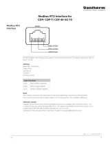
■Modbus RTU
MODBUS RTU (Remote Terminal Unit) Protocol is
a m essaging structure developed by Modicon in
1979, used to establish master-slave/client-server
communication between intelligent devices.
MODBUS is used to monitor and program
devices; to communicate intelligent devices
with sensors and instruments; to monitor field
devicesusingPCsandHMIs.
MODBU S is often applied in Gas and Oil appl ications,
but also in build ing, infrastructure, transportation and
energy, applications are m aking use of its benefits.
MG.28.E9.02 - VLT is a registered Danfoss trademark
11

VLT
®
2800 Series
■Motor coils
By fitt ing the motor coil module between the frequency
converter and the motor it is possible to use up
to 200 metres of unscreened/unarmoured motor
cable or 100 metres of screened/armoured motor
cable. The motor c oil m odule has an enc losure of
IP 20 and can be installed side-by-side.
NB!:
To have long motor cables and still comp ly
with EN55011-1A, motor coil and EMC filter
for long motor cables are needed.
NB!:
To comply with EN55011-1A the EMC filter for
long motor cables can only be fitted to a VLT
2800 with integral 1A filter (R1 opt ion).
See also the section EMC Emission.
Technical data for VLT 2803-2875 Motor coils
M ax. cable leng th (unscree ned/unarmoured)
1)
200 m
Max. cable length ( screened/armoured)
1)
100 m
Enclosure IP 20
Max. rated current
1)
16 A
Max. voltage
1)
480 V AC
Min. distance between VLT and motor coil Side-by-side
Min. distance above and below motor coil 100 mm
Dimensions H x W x D (mm)
2)
200 x 90 x 152
Weight 3.8 kg
1)
Parameter 411 Switching frequency =4500Hz.
2)
For mechanical dimensions see under
Mechanical d im e nsions.
See ordering number for motor coil module
under Accessories for VLT 2800.
MG.28.E9.02 - VLT is a registered Danfoss trademark
12

VLT
®
2800 Series
Introduction to VLT
2800
■RFI 1B filter
All frequency converters will ca use electromagnetic
noise in the mains supply when they are operating.
An RFI (Radio Frequency Interference) filter will reduce
theelectromagneticnoiseinthemainssupply.
Without an RFI filter there is a risk that a frequency
converter will disrupt other electrical components
that are connected to the mains and might
thus cause operating disruption.
By fitting an RFI 1B filter m od u le between the mains
supply and the VLT 2800, the VLT 2800 complies
with the EMC norm EN 55011-1B.
NB!:
To comply with EN 55011-1B the RFI 1B
filter module must be fitted together with a
VLT 2800 with integral 1A RFI filter.
Technical data for VLT 2803-2875 RFI 1B filter
Max. cable length (screened/armoured) 200-240 V 100 m (At 1A: 100 m)
Max. cable length (screened/armoured) 380-480 V 25 m (At 1A: 50 m)
Enclosure IP 20
Max. rated current 16 A
Max. Voltage 480 V AC
Max. voltage to earth 300 V AC
Min. distance between VLT and RFI 1B filter Side-by-Side
Min. distance above and below RFI 1B filter 100 mm
Dimensions H x W x D (mm)
1)
200 x 60 x 87
Weight 0.9 kg
1)
For mechanical dimensions see under
Mechanical d im e nsions.
See o rd eri n g number for RFI 1B filter module
under Accessories for VLT 2800.
MG.28.E9.02 - VLT is a registered Danfoss trademark
13

VLT
®
2800 Series
■RFI 1B/LC filter
The RFI 1B/LC filter contains both an RFI module
that complies with EN 55011-1B and an LC filter
that reduce s the acoustic noise.
LC filter
When a m otor is c ontrolled by a frequency converter, at
times you will be able to hear the acoustic noise from
the m otor. The noise, which is caused by the design of
the motor, is generated ever y time one of the inverter
contacts in the frequency converter is activated. The
frequency of the acousti c noise therefore corresponds
to the freque ncy converter’s connection frequency.
The filter reduces the voltage’s du/dt, the peak voltage
U
peak
and ripple current Itothemotor,sothatthe
current and voltage are almost sine-shaped. The
acoustic motor noise is thus reduced to a minimum.
Becauseoftheripplecurrentinthecoilssome
noisewillbeemittedbythecoils. Thisproblem
can be solved completely by fitting the filter
inside a cabinet or equivalent.
Danfoss can supply an LC filter for the frequency
converter, which m uffles the acoustic motor noise.
Beforethefiltersareputintouseyoumustensurethat:
- rated current is observed
- ma ins voltage is 200-480 V
- parameter 412 Variable sw itching frequency
is set to LC filter attached [3]
- output frequency is max. 120 Hz
See drawing on the next page.
Installation of thermistor (PTC)
The RFI 1B/LC filter has an integral thermistor (PTC),
which is activated if an overtemperature arises. The
frequency c onverter can be programmed to stop the
motor and activatee an alarm via a relay output or
a digital output if the the rmistor is act ivated.
The thermistor must be connected between terminal 50
(+10V) and one of the digital inputs 18, 19, 27 and 29.
In parameter 128 Motor thermal protection Thermistor
warning [1] or Thermistor trip [2] are selected.
The thermistor is connected as follows:
MG.28.E9.02 - VLT is a registered Danfoss trademark
14

VLT
®
2800 Series
Introduction to VLT
2800
■RFI 1B/LC filter
NB!:
To comply with EN 55011-1B the RFI 1B
filter module must be fitted to a VLT 2800
with integral 1A RFI filter.
NB!:
The 1B/LC filter is not suitable for 200 V devices
due to the high 1Ø input current.
Technical data for VLT 2803-2840 RFI 1B/LC filter
Max. cable length (screened/armoured) 380-480 V 25 m ( At 1A: 50 m)
Enclosure IP 20
Max. rated current 4.0 (Order no.: 195N3100); 9.1 (Order no.:
195N3101)
Max. voltage 480 V AC
Max. voltage to earth 300 V AC
Min. distance between VLT and RFI 1B/LC filter Side-by-Side
Mi n. distance above and below RFI 1B/LC filter 100 mm
Dimensions 195N3100 4.0 A H x W x D ( mm) 200 x 75 x 168
Dimensions 195N3101 9.1 A H x W x D ( mm) 267.5 x 90 x 168
Weight 195N3100 4.0 A 2.4 kg
Weight 195N3101 9.1 A 4.0 kg
MG.28.E9.02 - VLT is a registered Danfoss trademark
15

VLT
®
2800 Series
■EMC filter for long motor cables
NB!:
Set switching frequency, parameter
411, to 4500 Hz
NB!:
Fitting posit ion of frequency conve rter:
Vertical only.
NB!:
To have long motor cables and still comp ly
with EN55011-1A, motor coil and EMC filter
for long motor cables are needed.
NB!:
NB: To comply w ith EN55011-1A the EMC filter
for long motor cables can only be fitted to a
VLT 2800 with integral 1A filter (R1 o ption).
See also the section EMC Emission.
Technical data for VLT 2805-2875 380-480 V EMC filter for long motor cables
Max. cable length (screened/armoured) VLT 2805-2875 380-480 V: 100 m
Enclosure IP 20
Max. rated current 192H4719: 3.2 A, 192H4720: 9.0 A, 192H4893: 16 A
Input voltage range 3 x 380-480 V ± 10%
Mains fre quency 50-60 Hz
Input Terminals 2,5 mm
2
(192H4893 4 mm
2
)
Output Flexible cords with sleeves
Design Metal ho using (suited for foot print and side mo unting to V L T
2800)
Min. distance above and below filter 100 mm
Ambient temperature Ta= 50 °C
Dimensions 192H4719 H x W x D (mm)
1
244 x 75 x 45
Dimensions 192H4720 H x W x D (mm)
1
313 x 90 x 50
Dimensions 192H4893 H x W x D (mm)
1
313 x 140 x 50
See ordering numbers for EMC filter for long motor cables in Accessories for VLT 2800
1
For drawing and more detailed dimensions, see in Mechanical dimensions
■Control unit
The frequency converter is always supplied
with an integral control unit.
All displays are in the form of a six-digi t LED
display capable of showing one item of operating
data continuously during normal operation. As a
supplement to the display, there are three indicator
lamps for voltage (ON), warning (W A RNING) and
alarm (ALARM). Most of the frequency converter’s
parameter Setups can be changed immediately
via the integral control panel.
An LCP 2 control panel to be connected via a
plug to the front of the frequency converter is
available as an option. The LCP 2 control panel
can be installed up to 3 metres away from the
frequency converter, e.g. on a front panel, by means
of the accompanying mounting kit.
All d isplays of data are via a 4-line alpha-numerical
display, which in normal operat ion is able to show
4 operating data items and 3 operation modes
continuously. During programming, all the information
required for quick, efficient parameter Setup of the
freque ncy converter is displayed. As a supplement
to the display, there are three indicator lamps
for voltage (ON) , warning (WARNING) and alarm
(ALARM). Most of the frequency converter’s parameter
Setups can be changed immediately via the LCP
2 control panel. See also the section entitled The
LCP 2 control unit in the Design Guide.
MG.28.E9.02 - VLT is a registered Danfoss trademark
16

VLT
®
2800 Series
Introduction to VLT
2800
■Ordering numbers for VLT 2800 200-240 V
0,37 kW VLT 2803 1 x 220-240 V / 3 x 200-240 V
RFI Unit Profibus
DP
1)
3MBits/s
DeviceNet Ordering no.
- ST - - 195N0001
- SB - - 195N0002
R1 ST - - 195N0003
R1 SB - - 195N0004
-ST - 195N0005
-SB - 195N0006
R1 ST - 195N0007
R1 SB - 195N0008
-ST - 195N0009
-SB - 195N0010
R1 ST - 195N0011
R1 SB - 195N0012
0,55 kW VLT 2805 1 x 220-240 V / 3 x 200-240 V
RFI Unit Profibus
DP
1)
3MBits/s
DeviceNet Ordering no.
- ST - - 195N0013
- SB - - 195N0014
R1 ST - - 195N0015
R1 SB - - 195N0016
-ST - 195N0017
-SB - 195N0018
R1 ST - 195N0019
R1 SB - 195N0020
-ST - 195N0021
-SB - 195N0022
R1 ST - 195N0023
R1 SB - 195N0024
0,75 kW VLT 2807 1 x 220-240 V / 3 x 200-240 V
RFI Unit Profibus
DP
1)
3MBits/s
DeviceNet Ordering no.
- S T - - 195N0025
- SB - - 195N0026
R1 ST - - 195N0027
R1 SB - - 195N0028
-ST - 195N0029
-SB - 195N0030
R1 ST - 195N0031
R1 SB - 195N0032
-ST - 195N0033
-SB - 195N0034
R1 ST - 195N0035
R1 SB - 195N0036
1,1 kW VLT 2811 1 x 220-240 V / 3 x 200-240 V
RFI Unit Profibus
DP
1)
3MBits/s
DeviceNet Ordering no.
- S T - - 195N0037
- SB - - 195N0038
R1 ST - - 195N0039
R1 SB - - 195N0040
-ST - 195N0041
-SB - 195N0042
R1 ST - 195N0043
R1 SB - 195N0044
-ST - 195N0045
-SB - 195N0046
R1 ST - 195N0047
R1 SB - 195N0048
1,5 kW VLT 2815 1 x 220-240 V / 3 x 200-240 V
RFI Unit Profibus
DP
1)
3MBits/s
DeviceNet Ordering no.
- S T - - 195N0049
- SB - - 195N0050
R1 ST - - 195N0051
R1 SB - - 195N0052
-ST - 195N0053
-SB - 195N0054
R1 ST - 195N0055
R1 SB - 195N0056
-ST - 195N0057
-SB - 195N0058
R1 ST - 195N0059
R1 SB - 195N0060
2,2 kW VLT 2822 3 x 200-240 V
RFI Unit Profibus
DP
1)
3MBits/s
DeviceNet Ordering no.
- S T - - 195N0061
- SB - - 195N0062
R1 ST - - 195N0063
R1 SB - - 195N0064
-ST - 195N0065
-SB - 195N0066
R1 ST - 195N0067
R1 SB - 195N0068
-ST - 195N0069
-SB - 195N0070
R1 ST - 195N0071
R1 SB - 195N0072
MG.28.E9.02 - VLT is a registered Danfoss trademark
17

VLT
®
2800 Series
3,7 kW VLT 2840 3 x 200-240 V
RFI Unit Profibus
DP
1)
3MBits/s
DeviceNet Ordering no.
- S T - - 195N0073
- SB - - 195N0074
R1 ST - - 195N0075
R1 SB - - 195N0076
-ST - 195N0077
-SB - 195N0078
R1 ST - 195N0079
R1 SB - 195N0080
-ST - 195N0081
-SB - 195N0082
R1 ST - 195N0083
R1 SB - 195N0084
ST: Standard unit.
SB: Standard unit with integral brake.
R1: With RFI filter tha t complies w
ith EN 55011-1A.
NB!:
For VLT 2803-2815 with an R1 filter it is
only possible to connect single-phase mains
voltage 1 x 220 - 240 Volt.
1) Also available in 12 MBi
t/s version.
MG.28.E9.02 - VLT is a registered Danfoss trademark
18

VLT
®
2800 Series
Introduction to VLT
2800
■Ordering numbers for VLT 2800 380-480V
0,55kW VLT28053x380-480V
RFI Unit Profibus
DP
1)
3MBit/s
DeviceNet Ordering no.
- ST - - 195N1001
- SB - - 195N1002
R1 ST - - 195N1003
R1 SB - - 195N1004
-ST - 195N1005
-SB - 195N1006
R1 ST - 195N1007
R1 SB - 195N1008
-ST - 195N1009
-SB - 195N1010
R1 ST - 195N1011
R1 SB - 195N1012
0,75 kW VLT 2807 3 x 380-480 V
RFI Unit Profibus
DP
1)
3MBit/s
DeviceNet Ordering no.
- S T - - 195N1013
- SB - - 195N1014
R1 ST - - 195N1015
R1 SB - - 195N1016
-ST - 195N1017
-SB - 195N1018
R1 ST - 195N1019
R1 SB - 195N1020
-ST - 195N1021
-SB - 195N1022
R1 ST - 195N1023
R1 SB - 195N1024
1,1 kW VLT 2811 3 x 380-480 V
RFI Unit Profibus
DP
1)
3MBit/s
DeviceNet Ordering no.
- S T - - 195N1025
- SB - - 195N1026
R1 ST - - 195N1027
R1 SB - - 195N1028
-ST - 195N1029
-SB - 195N1030
R1 ST - 195N1031
R1 SB - 195N1032
-ST - 195N1033
-SB - 195N1034
R1 ST - 195N1035
R1 SB - 195N1036
1,5 kW VLT 2815 3 x 380-480 V
RFI Unit Profibus
DP
1)
3MBit/s
DeviceNet Ordering no.
- S T - - 195N1037
- SB - - 195N1038
R1 ST - - 195N1039
R1 SB - - 195N1040
-ST - 195N1041
-SB - 195N1042
R1 ST - 195N1043
R1 SB - 195N1044
-ST - 195N1045
-SB - 195N1046
R1 ST - 195N1047
R1 SB - 195N1048
2,2 kW VLT 2822 3 x 380-480 V
RFI Unit Profibus
DP
1)
3MBit/s
DeviceNet Ordering no.
- S T - - 195N1049
- SB - - 195N1050
R1 ST - - 195N1051
R1 SB - - 195N1052
-ST - 195N1053
-SB - 195N1054
R1 ST - 195N1055
R1 SB - 195N1056
-ST - 195N1057
-SB - 195N1058
R1 ST - 195N1059
R1 SB - 195N1060
3,0 kW VLT 2830 3 x 380-480 V
RFI Unit Profibus
DP
1)
3MBit/s
DeviceNet Ordering no.
- S T - - 195N1061
- SB - - 195N1062
R1 ST - - 195N1063
R1 SB - - 195N1064
-ST - 195N1065
-SB - 195N1066
R1 ST - 195N1067
R1 SB - 195N1068
-ST - 195N1069
-SB - 195N1070
R1 ST - 195N1071
R1 SB - 195N1072
MG.28.E9.02 - VLT is a registered Danfoss trademark
19

VLT
®
2800 Series
4,0 kW VLT 2840 3 x 380-480 V
RFI Unit Profibus
DP
1)
3MBit/s
DeviceNet Ordering no.
- S T - - 195N1073
- SB - - 195N1074
R1 ST - - 195N1075
R1 SB - - 195N1076
-ST - 195N1077
-SB - 195N1078
R1 ST - 195N1079
R1 SB - 195N1080
-ST - 195N1081
-SB - 195N1082
R1 ST - 195N1083
R1 SB - 195N1084
5,5 kW VLT 2855 3 x 380-480 V
RFI Unit Profibus
DP
1)
3MBit/s
DeviceNet Ordering no.
- S T - - 195N1085
- SB - - 195N1086
R1 ST - - 195N1087
R1 SB - - 195N1088
-ST - 195N1089
-SB - 195N1090
R1 ST - 195N1091
R1 SB - 195N1092
-ST - 195N1093
-SB - 195N1094
R1 ST - 195N1095
R1 SB - 195N1096
7,5 kW VLT 2875 3 x 380-480 V
RFI Unit Profibus
DP
1)
3MBit/s
DeviceNet Ordering no.
- S T - - 195N1097
- SB - - 195N1098
R1 ST - - 195N1099
R1 SB - - 195N1100
-ST - 195N1101
-SB - 195N1102
R1 ST - 195N1103
R1 SB - 195N1104
-ST - 195N1105
-SB - 195N1106
R1 ST - 195N1107
R1 SB - 195N1108
11 kW VLT 2880 3 x 380-480 V
RFI Unit Profibus
DP
1)
3MBit/s
DeviceNet Ordering no.
- S T - - 195N1109
- SB - - 195N1110
R3 ST - - 195N1111
R3 SB - - 195N1112
-ST - 195N1113
-SB - 195N1114
R3 ST - 195N1115
R3 SB - 195N1116
-ST - 195N1117
-SB - 195N1118
R3 ST - 195N1119
R3 SB - 195N1120
15 kW VLT 2881 3 x 380-480 V
RFI Unit Profibus
DP
1)
3MBit/s
DeviceNet Ordering no.
- S T - - 195N1121
- SB - - 195N1122
R3 ST - - 195N1123
R3 SB - - 195N1124
-ST - 195N1125
-SB - 195N1126
R3 ST - 195N1127
R3 SB - 195N1128
-ST - 195N1129
-SB - 195N1130
R3 ST - 195N1131
R3 SB - 195N1132
18.5 kW VLT 2882 3 x 380-480 V
RFI Unit Profibus
DP
1)
3MBit/s
DeviceNet Ordering no.
- S T - - 195N1133
- SB - - 195N1134
R3 ST - - 195N1135
R3 SB - - 195N1136
-ST - 195N1137
-SB - 195N1138
R3 ST - 195N1139
R3 SB - 195N1140
-ST - 195N1141
-SB - 195N1142
R3 ST - 195N1143
R3 SB - 195N1144
ST: Standard unit.
SB: Standard unit with integral brake.
R1: With RFI filter that complies with EN 55011-1A.
R3: With RFI filter that complies with EN 55011-1
B.
1) Also available in 12 M Bit/s.
MG.28.E9.02 - VLT is a registered Danfoss trademark
20
/