Page is loading ...

MAKING MODERN LIVING POSSIBLE
Design Guide
VLT
®
2800
www.danfoss.com/drives


Contents
1 Introduction to VLT 2800
6
1.1 Purpose of the Manual
6
1.2 Available Documentation
6
1.3 Document and Software Version
6
1.4 Technology
6
1.5 Approvals and Certifications
7
1.6 Disposal
8
1.7 Selecting the Correct Frequency Converter
9
1.7.1 Introduction 9
1.7.2 Enclosure 10
1.7.3 Brake 10
1.7.4 RFI Filter 10
1.7.5 Harmonic Filter 10
1.7.6 Control Unit 10
1.7.7 FC Protocol 11
1.7.8 Fieldbus Option 11
1.7.9 Motor Coils 11
1.7.10 RFI 1B Filter 12
1.7.11 RFI 1B/LC Filter 13
1.8 Order Form
15
1.9 PC Software
16
1.10 Accessories for VLT 2800
17
1.11 Brake Resistors
17
1.11.1 Dynamic Braking 17
1.11.2 Brake Set-up 18
1.11.3 Calculation of Brake Resistance 18
1.11.4 Calculation of Braking Power 18
1.11.5 Calculation of Peak Power of Brake Resistor 19
1.11.6 Calculation of Mean Power on Brake Resistor 19
1.11.7 Continuous Braking 19
1.11.8 DC Injection Braking 19
1.11.9 AC-braking 19
1.11.10 Optimal Braking Using Resistor 20
1.11.11 Brake Cable 20
1.11.12 Protective Functions During Installation 20
1.11.13 Brake Resistors 22
1.12 LCP Operation
23
1.12.1 Control Unit 23
1.12.2 Control Keys 23
Contents Design Guide
MG27E402 Danfoss A/S © Rev. May/2014 All rights reserved. 1

1.12.3 Manual Initialisation 24
1.12.4 Display Readout States 24
1.12.5 Hand Auto 25
1.12.6 Automatic Motor Tuning 25
1.13 LCP 2 Control Unit
26
1.13.1 Introduction 26
1.13.2 Control Keys for Parameter Set-up 26
1.13.3 Indicator Lights 27
1.13.4 Local Control 27
1.13.5 Displayed Data Items 28
1.13.6 Display Modes 28
1.13.7 Parameter Set-up 29
1.13.8 Quick Menu with LCP 2 Control Unit 29
1.13.9 Parameter Selection 30
1.13.10 Manual Initialisation 31
2 Safety
32
2.1 Safety Symbols
32
2.2 Qualified Personnel
32
2.3 Safety Precautions
32
3 Installation
34
3.1 Mechanical Dimensions
34
3.1.1 Overview 34
3.1.2 Enclosure B 34
3.1.3 Enclosure C 34
3.1.4 Enclosure D 35
3.1.5 Motor Coils (195N3110) 35
3.1.6 RFI 1B Filter (195N3103) 35
3.1.7 Terminal Cover 35
3.1.8 IP21 Solution 36
3.1.9 EMC Filter for Long Motor Cables 37
3.2 Mechanical Installation
38
3.3 Electrical Installation
39
3.3.1 High Voltage Warning 39
3.3.2 Grounding 39
3.3.3 Cables 39
3.3.4 Screened/armoured Cables 40
3.3.5 Extra Protection 40
3.3.6 High Voltage Test 40
3.3.7 EMC-correct Electrical Installation 41
Contents Design Guide
2 Danfoss A/S © Rev. May/2014 All rights reserved. MG27E402

3.3.8 Use of EMC Compliant Cables 42
3.3.9 Grounding of Screened/armoured Control Cables 43
3.3.10 Electrical Wiring 44
3.3.11 Electrical Connection 45
3.4 Terminals
47
3.4.1 Safety Clamp 47
3.4.2 Pre-fuses 48
3.4.3 Mains Connection 48
3.4.4 Motor Connection 48
3.4.5 Direction of Motor Rotation 49
3.4.6 Parallel Connection of Motors 50
3.4.7 Motor Cables 50
3.4.8 Thermal Motor Protection 50
3.4.9 Brake Connection 50
3.4.10 Ground Connection 51
3.4.11 Load Sharing 51
3.4.12 Tightening Torque for Power Terminals 52
3.4.13 Control of Mechanical Brake 52
3.4.14 Access to Control Terminals 52
3.4.15 Control Cables 52
3.4.16 Control Terminals 54
3.4.17 Relay Connection 55
3.4.18 Switches 1-4 55
3.4.19 VLT Motion Control Tool MCT 10 Set-up Software 55
3.4.20 Sub D Plug 56
3.5 Connection Examples
56
3.5.1 Start/Stop 56
3.5.2 Pulse Start/Stop 56
3.5.3 Speed Up/Down 57
3.5.4 Potentiometer Reference 57
3.5.5 Connection of a 2-Wire Transmitter 57
3.5.6 4-20 mA Reference 57
3.5.7 50 Hz Counter-clockwise to 50 Hz Clockwise 58
3.5.8 Preset References 58
3.5.9 Connection of Mechanical Brake 59
3.5.10 Counter Stop Through Terminal 33 59
3.5.11 Use of Internal PID-Controller - Closed Loop Process Control 59
4 Programming
61
4.1 Operation & Display
61
4.2 Load and Motor
68
Contents Design Guide
MG27E402 Danfoss A/S © Rev. May/2014 All rights reserved. 3

4.3 References & Limits
77
4.4 Inputs and Outputs
84
4.5 Special Functions
92
4.6 Enhanced Sleep Mode
101
4.7 Serial communication
106
4.7.1 Protocols 106
4.7.2 Telegram Traffic 106
4.7.3 Telegram Structure 106
4.7.4 Data Character (Byte) 107
4.7.5 Process Words 110
4.7.6 Control Word According to FC Protocol 110
4.7.7 Status Word According to FC Profile 112
4.7.8 Control Word According to Fieldbus Profile 113
4.7.9 Status Word According to Profidrive Protocol 113
4.7.10 Serial Communication Reference 114
4.7.11 Present Output Frequency 115
4.8 Serial Communication Parameters
116
4.9 Technical Functions
123
5 All about VLT 2800
127
5.1 Special Conditions
127
5.1.1 Galvanic Isolation (PELV) 127
5.1.2 Ground Leakage Current and RCD Relays 127
5.1.3 Extreme Operating Conditions 128
5.1.4 dU/dt on Motor 128
5.1.5 Switching on the Input 128
5.1.6 Peak Voltage on Motor 128
5.1.7 Acoustic Noise 129
5.1.8 Derating for Ambient Temperature 129
5.1.9 Temperature-Dependent Switching Frequency 129
5.1.10 Derating for Air Pressure 130
5.1.11 Derating for Running at Low Speed 130
5.1.12 Derating for Long Motor Cables 130
5.1.13 Derating for High Switching Frequency 130
5.1.14 Vibration and Shock 131
5.1.15 Air Humidity 131
5.1.16 UL Standard 131
5.1.17 Efficiency 131
5.1.18 Mains Supply Interference/Harmonics 132
5.1.19 Power Factor 132
5.1.20 Generic EMC Standards / Product Standards 133
Contents Design Guide
4 Danfoss A/S © Rev. May/2014 All rights reserved. MG27E402

5.1.21 EMC Immunity 134
5.1.22 Harmonic Current Emission 135
5.1.23 Aggressive Environments 135
5.2 Display and Messages
136
5.2.1 Display Readout 136
5.2.2 Warnings and Alarm Messages 136
5.2.3 Warning Words, Extended Status Words and Alarm Words 140
5.3 General Technical Data
141
5.4 Mains Supply
146
5.4.1 Mains Supply 1x220-240 V/3x200-240 V 146
5.4.2 Mains Supply 3x380-480 V 147
5.5 Parameter List with Factory Settings
148
Index
155
Contents Design Guide
MG27E402 Danfoss A/S © Rev. May/2014 All rights reserved. 5

1 Introduction to VLT 2800
1.1 Purpose of the Manual
This Design Guide is intended for project and systems
engineers, design consultants, and application and product
specialists. Technical information is provided to understand
the capabilities of the frequency converter for integration
into motor control and monitoring systems. Details
concerning operation, requirements, and recommendations
for system integration are described. Information is proved
for input power characteristics, output for motor control,
and ambient operating conditions for the converter.
Also included are safety features, fault condition
monitoring, operational status reporting, serial communi-
cation capabilities, and programmable options and
features. Design details such as site requirements, cables,
fuses, control wiring, the size and weight of units, and
other critical information necessary to plan for system
integration is also provided.
Reviewing the detailed product information in the design
stage is helpful in developing a well-conceived system
with optimal functionality and efficiency.
VLT
®
is a registered trademark.
1.2
Available Documentation
Documentation is available to understand specific
frequency converter functions and programming.
•
VLT 2800 Quick Guide
•
VLT 2800 Design Guide
•
VLT 2800 Filter Instruction
•
Brake Resistor Manual
•
Profibus DP V1 Manual
•
Profibus DP Manual
•
VLT 2800 DeviceNet Manual
•
Metasys N2 Manual
•
Modbus RTU Manual
•
Precise Stop
•
Wobble Function
•
VLT 2800 NEMA 1 Terminal Covering
•
VLT 2800 LCP Remote-mounting Kit
•
Protection against Electrical Hazards
1.3
Document and Software Version
Edition Remarks Software version
MG27E4 Replaces MG27E3 3.2X
1.4 Technology
1.4.1 Control Principle
A frequency converter rectifies AC voltage from the mains
supply into DC voltage, and changes this voltage to an AC
voltage with variable amplitude and frequency.
The motor thus receives a variable voltage and frequency,
which enables infinitely variable speed control of 3-phase,
standard AC motors.
Illustration 1.1 Control Principle
1. Mains voltage
1x220-240 V AC, 50/60 Hz
3x200-240 V AC, 50/60 Hz
3x380-480 V AC, 50/60 Hz
2. Rectifier
3-phase rectifier bridge which rectifies AC voltage into DC
voltage.
3. Intermediate circuit
DC voltage 2 x mains voltage [V].
4. Intermediate circuit coils
Evens out the intermediate circuit current and limits the
load on mains and components (mains transformer, cables,
fuses and contactors).
5. Intermediate circuit condenser
Evens out the intermediate circuit voltage.
6. Inverter
Converts DC voltage into a variable AC voltage with a
variable frequency.
7. Motor voltage
Variable AC voltage depending on supply voltage.
Variable frequency: 0.2-132/1-590 Hz.
8. Control card
The control card controls the inverter which generates the
pulse pattern converting the DC voltage into variable AC
voltage with a variable frequency.
Introduction to VLT 2800
Design Guide
6 Danfoss A/S © Rev. May/2014 All rights reserved. MG27E402
1
1

1.4.2 VLT 2800 Control Principle
A frequency converter is an electronic unit which is able to
infinitely variably control the RPM of an AC motor. The
frequency converter controls the motor speed by
converting the regular voltage and frequency from mains,
e.g. 400 V/50 Hz, into variable magnitudes. Today, the
frequency converter controlled AC motor is a natural part
of all types of automated plants.
The frequency converter has an inverter control system
called VVC (Voltage Vector Control). VVC controls an
induction motor by energising it with a variable frequency
and a voltage suitable for it. If the motor load changes, so
does its energising and speed. That is why the motor
current is measured on an ongoing basis, and a motor
model is used to calculate the actual voltage requirement
and slip of the motor.
1.4.3
Programmable Inputs and Outputs in
4 Set-ups
In the frequency converter, it is possible to program the
different control inputs and signal outputs and to select 4
different user-defined set-ups for most parameters.
Program the required functions on the control panel or via
serial communication.
1.4.4
Mains Protection
The frequency converter is protected against the transients
that occur on the mains sometimes, e.g. if coupling with a
phase compensation system, or if fuses blow when
lightning strikes.
Rated motor voltage and full torque can be maintained
down to approx. 10% undervoltage in the mains supply.
As all 400 V units in the VLT 2800 Series have intermediate
circuit coils, there is only a low amount of harmonic mains
supply interference. This gives a good power factor (lower
peak current), which reduces the load on the mains instal-
lation.
1.4.5
Frequency Converter Protection
The current measurement in the intermediate circuit
constitutes perfect protection of the frequency in case
there is a short-circuit or a ground fault on the motor
connection.
Constant monitoring of the intermediate circuit current
enables switching on the motor output, e.g. with a
contactor.
Efficient monitoring of the mains supply means that the
unit stops if a phase drop-out occurs. In this way, the
inverter and the condensers in the intermediate circuit are
not overloaded, which would dramatically reduce the
service life of the frequency converter. The frequency
converter offers temperature protection as standard. If
there is a thermal overload, this function cuts out the
inverter.
1.4.6 Reliable Galvanic Isolation
In the frequency converter, all digital inputs/outputs,
analog inputs/outputs and the terminals for serial
communication are supplied from or in connection with
circuits that comply with PELV requirements. PELV is also
complied with in relation to relay terminals, so that they
can be connected to the mains potential.
For further information, see chapter 5.1.1 Galvanic Isolation
(PELV).
1.4.7
Advanced Motor Protection
The frequency converter has integral electronic motor
protection. The frequency converter calculates the motor
temperature on the basis of current, frequency and time.
As opposed to traditional, bimetallic protection, electronic
protection takes account of reduced cooling at low
frequencies because of reduced fan speed (motors with
internal fan). This function cannot protect the individual
motors when motors are connected in parallel. Thermal
motor protection can be compared to a protective motor
switch, CTI.
See chapter 5.1.1 Galvanic Isolation (PELV) for further
information.
WARNING
If motors are connected in parallel, individual motors still
have the risk of overheating. To protect the frequency
converter from overheating, install a thermistor and
connect it to the thermistor input (digital input) of the
frequency converter. See chapter 4.2.2 Termisk motorbe-
skyttelse -parameter 128 for further information.
1.5 Approvals and Certifications
The frequency converter complies with UL508C thermal
memory retention requirements. For more information,
refer to chapter 4.2.2 Termisk motorbeskyttelse -parameter
128.
Introduction to VLT 2800
Design Guide
MG27E402 Danfoss A/S © Rev. May/2014 All rights reserved. 7
1
1

What is CE labelling?
The purpose of CE labelling is to avoid technical obstacles
to trade within EFTA and the EU. The EU has introduced
the CE label as a simple way of showing whether a
product complies with the relevant EU directives. The CE
label says nothing about the specifications or quality of
the product. Frequency converters are regulated by 3 EU
directives:
The machinery directive (98/37/EEC)
All machines with critical moving parts are covered by the
machinery directive. Since a frequency converter is largely
electrical, it does not fall under the machinery directive.
However, if a frequency converter is supplied for use in a
machine, Danfoss provides information on safety aspects
relating to the frequency converter. Danfoss does this with
a manufacturer's declaration.
The low-voltage directive (73/23/EEC)
Frequency converters must be CE labelled in accordance
with the low-voltage directive. The directive applies to all
electrical equipment and appliances used in the 50-1000 V
AC and the 75-1500 V DC voltage ranges. Danfoss CE
labels in accordance with the directive and issues a
declaration of conformity upon request.
The EMC directive (89/336/EEC)
EMC is short for electromagnetic compatibility. The
presence of electromagnetic compatibility means that the
mutual interference between different components/
appliances is so small that the functioning of the
appliances is not affected.
Danfoss CE labels in accordance with the directive and
issues a declaration of conformity upon request. To carry
out EMC-correct installation, this manual gives detailed
instructions for installation. In addition, Danfoss specifies
the standards which our different products comply with.
The frequency converter is most often used by profes-
sionals of the trade as a complex component forming part
of a larger appliance, system or installation. It must be
noted that the responsibility for the final EMC properties of
the appliance, system or installation rests with the installer.
1.6
Disposal
Do not dispose of equipment containing
electrical components together with
domestic waste.
Collect it separately in accordance with
local and currently valid legislation.
Introduction to VLT 2800 Design Guide
8 Danfoss A/S © Rev. May/2014 All rights reserved. MG27E402
1
1

1.7 Selecting the Correct Frequency Converter
1.7.1 Introduction
This section explains how to specify and order a VLT 2800.
The frequency converter must be selected on the basis of the present motor current at maximum loading of the unit. The
frequency converter's rated output current I
INV.
must be equal to or greater than the required motor current.
Mains Voltage
VLT 2800 is available for 2 mains voltage ranges:
•
200-240 V and
•
380-480 V.
Select whether the frequency converter is connected to a mains voltage of:
•
1x220-240 V single-phase AC voltage
•
3x200-240 V 3-phase AC voltage
•
3x380-480 V 3-phase AC voltage
Typical shaft output
P
INV.
Maximum constant output current I
INV.
Maximum constant output power at
230 V S
INV.
Type [kW] [HP] [A] [kVA]
2803 0.37 0.5 2.2 0.9
2805 0.55 0.75 3.2 1.3
2807 0.75 1.0 4.2 1.7
2811 1.1 1.5 6.0 2.4
2815 1.5 2.0 6.8 2.7
2822 2.2 3.0 9.6 3.8
2840 3.7 5.0 16 6.4
Table 1.1 1x220-240 V Mains Voltage
Typical shaft output
P
INV.
Maximum constant output current I
INV.
Maximum constant output power at
230 V S
INV.
Type [kW] [HP] [A] [kVA]
2803 0.37 0.5 2.2 0.9
2805 0.55 0.75 3.2 1.3
2807 0.75 1.0 4.2 1.7
2811 1.1 1.5 6.0 2.4
2815 1.5 2.0 6.8 2.7
2822 2.2 3.0 9.6 3.8
2840 3.7 5.0 16.0 6.4
Table 1.2 3x200-240 V Mains Voltage
Introduction to VLT 2800
Design Guide
MG27E402 Danfoss A/S © Rev. May/2014 All rights reserved. 9
1
1

Typical shaft output
P
INV.
Maximum constant output current I
INV.
Maximum constant output power at
400 V S
INV.
Type [kW] [HP] [A] [kVA]
2805 0.55 0.75 1.7 1.1
2807 0.75 1.0 2.1 1.7
2811 1.1 1.5 3.0 2.0
2815 1.5 2.0 3.7 2.6
2822 2.2 3.0 5.2 3.6
2830 3.0 4.0 7.0 4.8
2840 4.0 5.0 9.1 6.3
2855 5.5 7.5 12.0 8.3
2875 7.5 10.0 16.0 11.1
2880 11 15 24 16.6
2881 15 20 32 22.2
2882 18.5 25 37.5 26.0
Table 1.3 3x380-480 V Mains Voltage
1.7.2
Enclosure
All VLT 2800 units are supplied with IP20 enclosure as
standard.
This enclosure level is ideal for panel mounting in areas
where a high degree of protection is required; at the same
time IP20 enclosures allow side-by-side installation without
any need for extra cooling equipment.
IP20 units can be upgraded with IP21/top cover and/or
NEMA 1 by fitting a terminal cover. See ordering number
for terminal cover in chapter 1.10 Accessories for VLT 2800.
In addition, VLT 2880-82 and 2840 PD2 units are supplied
with NEMA 1 enclosure as standard.
1.7.3
Brake
Danfoss VLT 2800 is available with an integral brake
module (does not apply to 2822 and 2840 in 200 V with
combined single-phase/3-phase supply - type code PD2).
See also chapter 1.11.13 Brake Resistors for brake resistor
ordering numbers.
1.7.4
RFI Filter
VLT 2800 is available with or without an integral 1A RFI-
filter. The integral 1A RFI filter complies with EMC
standards EN 55011-1A.
With an integral RFI filter there is compliance with EN
55011-1B with a maximum 15-metres screened/armoured
motor cable on VLT 2803-2815 1x220-240 V.
VLT 2880-82 with integral 1B filter comply with EMC
standard EN 50011-1B.
1.7.5
Harmonic Filter
The harmonic currents do not affect power consumption
directly, but they increase the heat losses in the installation
(transformer, cables). That is why, in a system with a
relatively high percentage of rectifier load, it is important
to keep the harmonic currents at a low level so as to avoid
a transformer overload and high cable temperature. For
the purpose of ensuring low harmonic currents, VLT
2822-2840 3x200-240 V and VLT 2805-2882 380-480 V are
fitted with coils in their intermediate circuit as standard.
This reduces the input current I
RMS
by typically 40%.
Please Note that 1x220-240 V units up to 1.5 kW are not
supplied with coils in their intermediate circuit.
1.7.6
Control Unit
The frequency converter is always supplied with an
integral control unit.
All displays are in the form of a 6-digit LED display capable
of showing one item of operating data continuously
during normal operation. As a supplement to the display,
there are 3 indicator lights for voltage (ON), warning
(WARNING) and alarm (ALARM). Most of the frequency
converter's parameter set-ups can be changed immediately
via the integral control panel.
An LCP 2 control panel to be connected via a plug to the
front of the frequency converter is available as an option.
The LCP 2 control panel can be installed up to 3 metres
away from the frequency converter, e.g. on a front panel,
with the accompanying mounting kit.
All displays of data are via a 4-line alpha-numerical display,
which in normal operation is able to show 4 operating
data items and 3 operation modes continuously. During
programming, all the information required for quick,
efficient parameter set-up of the frequency converter is
displayed. As a supplement to the display, there are 3
Introduction to VLT 2800 Design Guide
10 Danfoss A/S © Rev. May/2014 All rights reserved. MG27E402
1
1

indicator lights for voltage (ON), warning (WARNING) and
alarm (ALARM). Most of the frequency converter's
parameter set-ups can be changed immediately via the
LCP 2 control panel. See chapter 1.13.1 Introduction for
more details.
1.7.7 FC Protocol
Danfoss frequency converters are able to fulfill many
different functions in a monitoring system. The frequency
converter can be integrated directly in an overall
surveillance system, which allows detailed process data to
be transferred via serial communication.
The protocol standard is based on an RS-485 bus system
with a maximum transmission speed of 9600 baud. The
following frequency converter profiles are supported as
standard:
•
FC Drive, which is a profile adapted to Danfoss.
•
Profidrive, which supports the profidrive profile.
See chapter 4.8 Serial Communication Parameters for further
details of telegram structure and drive profile.
1.7.8
Fieldbus Option
The increasing information requirements in industry make
it necessary to collect or visualise different process data.
Important process data help the system technician with
the daily monitoring of the system. The large amounts of
data involved in major systems make a higher transmission
speed than 9600 baud desirable.
Fieldbus option
Profibus
Profibus is a fieldbus system, which can be used for linking
automation devices such as sensors and actuators with the
controls via a 2-conductor cable. Profibus DP is a fast
communication protocol made specially for communication
between the automation system and various types of
equipments.
Profibus is a registered trade mark.
DeviceNet
DeviceNet fieldbus systems can be used for linking
automation devices such as sensors and actuators with the
controls via a 4-wire conductor cable.
DeviceNet is a medium-speed communication protocol
made specially for communication between the
automation system and various types of equipment. Units
with DeviceNet protocol cannot be controlled by FC
protocol and Profidrive protocol.
MCT 10 Set-up Software can be used on the Sub D plug.
1.7.9
Motor Coils
By fitting the motor coil module between the frequency
converter and the motor, it is possible to use up to 200 m
of unscreened/unarmoured motor cable or 100 m of
screened/armoured motor cable. The motor coil module
has an IP20 enclosure and can be installed side-by-side.
To have long motor cables and still comply with
EN55011-1A, motor coil and EMC filter for long motor
cables are needed.
To comply with EN55011-1A, the EMC filter for long motor
cables can only be fitted to a VLT 2800 with integral 1A
filter (R1 option).
Refer to chapter 5.1.21 EMC Compliance for more details.
Illustration 1.2 Motor Cable Example
Introduction to VLT 2800 Design Guide
MG27E402 Danfoss A/S © Rev. May/2014 All rights reserved. 11
1
1

Maximum cable length (unscreened/
unarmoured)
1)
200 m
Maximum cable length (screened/armoured)
1)
100 m
Enclosure IP20
Maximum rated current
1)
16 A
Maximum voltage
1)
480 V AC
Minimum distance between frequency
converter and motor coil
Side-by-side
Minimum distance above and below motor
coil
100 mm
Mounting Vertical mounting
only
Dimensions HxWxD (mm)
2)
200x90x152
Weight 3.8 kg
Table 1.4 Technical Data for VLT 2803-2875 Motor Coils
1) Parameter 411 Switching frequency=4500 Hz.
2) For mechanical dimensions see chapter 3.1.1 Overview.
For ordering numbers for motor coil module, see
chapter 1.10 Accessories for VLT 2800.
1.7.10
RFI 1B Filter
All frequency converters cause electromagnetic noise in
the mains supply when they are operating. An RFI (radio
frequency interference) filter reduces the electromagnetic
noise in the mains supply. Without an RFI filter, there is a
risk that a frequency converter disrupts other electrical
components that are connected to the mains and might
thus cause operating disruption. By fitting an RFI 1B filter
module between the mains supply and the VLT 2800, the
VLT 2800 complies with the EMC norm EN 55011-1B.
To comply with EN 55011-1B, the RFI 1B filter module must
be fitted together with a VLT 2800 with integral 1A RFI
filter.
Illustration 1.3 RFI 1B Filter Example
Maximum cable length (screened/armoured)
200-240 V
100 m (At 1A: 100
m)
Maximum cable length (screened/armoured)
380-480 V
25 m (At 1A: 50
m)
Enclosure IP20
Maximum rated current 16 A
Maximum Voltage 480 V AC
Maximum voltage to ground 300 V AC
Minimum distance between VLT and RFI 1B
filter
Side-by-side
Minimum distance above and below RFI 1B
filter
100 mm
Mounting Vertical mounting
only
Dimensions HxWxD (mm) 200x60x87
Weight 0.9 kg
Table 1.5 Technical Data for VLT 2803–2875 RFI 1B Filter
For ordering number for RFI 1B filter module, see
chapter 1.10 Accessories for VLT 2800.
Introduction to VLT 2800
Design Guide
12 Danfoss A/S © Rev. May/2014 All rights reserved. MG27E402
1
1

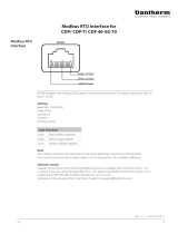
1.7.11 RFI 1B/LC Filter
The RFI 1B/LC filter contains both an RFI module that
complies with EN 55011-1B, and a LC filter that reduces
the acoustic noise.
LC filter
Illustration 1.4 LC Filter
When a motor is controlled by a frequency converter,
acoustic noise may be heard from the motor. The noise,
which is caused by the design of the motor, is generated
every time one of the inverter contacts in the frequency
converter is activated. The frequency of the acoustic noise
therefore corresponds to the frequency converter's
connection frequency.
The filter reduces the voltage's dU/dt, the peak voltage
U
peak
and ripple current ΔI to the motor, so that the
current and voltage are almost sine-shaped. The acoustic
motor noise is thus reduced to a minimum.
Because of the ripple current in the coils, some noise is
emitted by the coils. This problem can be solved
completely by fitting the filter inside a cabinet or
equivalent.
Danfoss can supply an LC filter for the VLT series 2800,
which muffles the acoustic motor noise. Before the filters
are put into use, ensure that:
•
Rated current is observed.
•
Mains voltage is 200-480 V.
•
Parameter 412 Variable switching frequency is set
to [3] LC filter attached.
•
Output frequency is max. 120 Hz.
Refer to Illustration 1.7 for a connection example of LC
filter.
Installation of thermistor (PTC)
The RFI 1B/LC filter has an integral thermistor (PTC), which
is activated if an overtemperature arises. The frequency
converter can be programmed to stop the motor and
activate an alarm via a relay output or a digital output if
the thermistor is activated.
Illustration 1.5 Thermistor Installation
The thermistor must be connected between terminal 50
(+10 V) and one of the digital inputs 18, 19, 27 and 29.
In parameter 128 Thermal motor protection, [1] Thermistor
warning or [2] Thermistor trip is selected.
Illustration 1.7 shows the thermistor connection.
Illustration 1.6 Thermistor Connection
To comply with EN 55011-1B, the RFI 1B filter module must
be fitted to a VLT 2800 with integral 1A RFI filter.
NOTICE
The 1B/LC filter is not suitable for 200 V devices due to
the high 1Ø input current.
Introduction to VLT 2800 Design Guide
MG27E402 Danfoss A/S © Rev. May/2014 All rights reserved. 13
1
1

Illustration 1.7 Connection Example for RFI 1B/LC Filter
Maximum cable length
(screened/armoured) 380-480 V
25 m (At 1A: 50 m)
Enclosure IP20
Maximum rated current 4.0 (Order no.: 195N3100); 9.1
(Order no.: 195N3101)
Maximum voltage 480 V AC
Maximum voltage to ground 300 V AC
Minimum distance between VLT
and RFI 1B/LC filter
Side-by-side
Minimum distance above and
below RFI 1B/LC filter
100 mm
Mounting Vertical mounting only
Dimensions 195N3100 4.0 A
HxWxD (mm)
200x75x168
Dimensions 195N3101 9.1 A
HxWxD (mm)
267.5x90x168
Weight 195N3100 4.0 A 2.4 kg
Weight 195N3101 9.1 A 4.0 kg
Table 1.6 Technical Data for VLT 2803–2875 RFI 1B/LC filter
Introduction to VLT 2800
Design Guide
14 Danfoss A/S © Rev. May/2014 All rights reserved. MG27E402
1
1

1.8 Order Form
How to order
A type code defines the specific configuration of the VLT
®
2800 frequency converter. Use Illustration 1.8 to create a type
code string for the desired configuration.
A dedicated drive configurator is available at www.danfoss.com/drives. It is recommended to use the configurator to get the
specific ordering number.
195NA026.24
VLT 2 8 P B 2 0 S R D B F
Power Sizes
e. g. 2815
Application range
Process
P
Mains voltage
1x220-240 V
1x220-240 V
3x200-240 V
3x200-240 V
S2
D2
T2
T4
1)
2)
3x380-480 V
5)
6)
2805 0.55 kW
2807 0.75 kW
2811 1.1 kW
2815 1.5 kW
2822 2.2 kW
2830 3.0 kW
2840 4.0 kW
2855 5.5 kW
2875 7.5 kW
2880 11.0 kW
2881 15.0 kW
2882 18.5 kW
2803 0.37 kW
2805 0.55 kW
2807 0.75 kW
2811 1.1 kW
2815 1.5 kW
2822 2.2 kW
2840 3.7 kW
2822 2.2 kW
2840 3.7 kW
Enclosure
IP 20
Standard with brake
B20
SB
RFI-lter
Without lter
With integral 1A lter
(2803-2875)
With integral 1B lter
(2880-2882)
With integral 1A lter
For RCD use
With integral 1A lter
For IT mains (2805-2840)
R0
R1
R3
R4
R5
3)
4)
A 0 0 C 1
Display unit
with built-in display unit
LCP display unit is an option
Code no. : 175N0131
Cable for LCP - Code no.: 175Z0929
DB
Fieldbus
Without eldbus
With Probus DP 12 MBit/s
With DeviceNet
F00
F12
F30
C1
1) S2 = Unit can only be ordered with RFI lter
2) D2 = Unit cannot be ordered with RFI lter
3) = Unit can only be ordered with S2
4) = Unit can only be ordered with T4
5) = Only available in 2822PD2 STRO version
6) = Only available in 2840PD2 STRO version
Coating
Coated printed circuit boards
B
Illustration 1.8 Type Code Definition
Introduction to VLT 2800
Design Guide
MG27E402 Danfoss A/S © Rev. May/2014 All rights reserved. 15
1
1

1.9 PC Software
MCT 10 Set-up Software
All frequency converters are equipped with a serial
communication port. Danfoss provides a PC tool for
communication between PC and frequency converter, VLT
Motion Control Tool MCT 10 Set-up Software.
MCT 10 Set-up Softwarehas been designed as an easy-to-
use interactive tool for setting parameters in the frequency
converters.
The MCT 10 Set-up Software can be used for:
•
Planning a communication network off-line. MCT
10 Set-up Software contains a complete
frequency converter database.
•
Commissioning frequency converters on line.
•
Saving settings for all frequency converters.
•
Replacing a frequency converter in a network.
•
Expanding an existing network.
•
Supporting future developed frequency
converters.
MCT 10 Set-up Software support Profibus DP-V1 via a
master class 2 connection. It makes it possible to read/
write parameters on-line in a frequency converter via the
Profibus network. This eliminates the need for an extra
communication network.
The MCT 10 Set-up Software can be downloaded at:
www.danfoss.com/BusinessAreas/DrivesSolutions/Software-
download/. Select the licensed version to use all functions,
or the free version to use limited functions.
MCT 31 Harmonic Calculation Tool
The MCT 31 Harmonic Calculation tool determines the
degree of voltage pollution on the grid and needed
precaution. Download the free MCT 31 Harmonic
Calculation Tool from www.danfoss.com/BusinessAreas/
DrivesSolutions/Softwaredownload/.
Introduction to VLT 2800 Design Guide
16 Danfoss A/S © Rev. May/2014 All rights reserved. MG27E402
1
1

1.10 Accessories for VLT 2800
Type Description Ordering no.
Motor coil The motor coil module can be used for VLT 2803-2875 195N3110
RFI 1B filter The RFI 1B filter module can be used for VLT 2803-2875 195N3103
RFI 1B/LC filter 4 A The RFI 1B/LC filter 4 A can be used for VLT 2803-2805 200-240 V and VLT
2805-2815 380-400 V
195N3100
RFI 1B/LC filter 9.1 A RFI 1B/LC filter 9.1 A can be used for VLT 2807-2815 200-240 V and VLT
2822-2840 380-400 V
195N3101
EMC filter EMC filter for long motor cables can be used for VLT 2805-2815 380-480 V 192H4719
EMC filter EMC filter for long motor cables can be used for VLT 2822-2840 380-480 V 192H4720
EMC filter EMC filter for long motor cables can be used for VLT 2855-2875 380-480 V 192H4893
NEMA 1 terminal cover VLT 2803-2815 200-240 V, VLT 2805-2815 380-480 V 195N1900
NEMA 1 terminal cover VLT 2822 200-240 V, VLT 2822-2840 380-480 V 195N1901
NEMA 1 terminal cover VLT 2840, VLT 2840 PD2 200-240 V, VLT 2855-2875 380-480 V 195N1902
IP 21 top cover VLT 2803-2815 200-240 V, VLT 2805-2815 380-480 V 195N2179
IP 21 top cover VLT 2822 200-240 V, VLT 2822-2840 380-480 V 195N2180
IP 21 top cover VLT 2840 200-240 V, VLT 2822 PD2, VLT 2855-2875 380-480 V 195N2181
IP 21 top cover VLT 2880-2882 380-480 V, VLT 2840 PD2 195N2182
LCP 2 control unit LCP 2 for programming the frequency converter 175N0131
Cable for LCP 2 control unit Cable from LCP 2 to frequency converter 175Z0929
DeviceNet cable Cable for DeviceNet connection 195N3113
LCP 2 remote-mounting kit Kit for remote-mounting of LCP 2 (incl. 3 m cable, excl. LCP 2) 175Z0850
LOP (Local Operation Pad) LOP can be used for setting the reference and start/stop via the control
terminals.
175N0128
MCT 10 Set-up software 130B1000
Table 1.7 Accessory List
1.11
Brake Resistors
1.11.1 Dynamic Braking
With the VLT 2800, the dynamic braking quality in an
application can be improved in 2 ways, either with brake
resistors or AC braking.
Danfoss offers a complete range of brake resistors for all
VLT 2800 frequency converters.
A brake resistor applies a load to the intermediate circuit
during braking, thereby ensuring that the brake power can
be absorbed by the brake resistor.
Without a brake resistor, the intermediate circuit voltage of
the frequency converter may continue to rise, until cutting
out for protection. Using a brake resistor can brake quickly
with large loads, e.g. on a conveyor belt.
Danfoss has selected a solution in which the brake resistor
is not integrated into the frequency converter. This gives
the user the following advantages:
•
The resistor's cycle time can be selected as
required.
•
The heat generated during braking can be
diverted outside the panel cabinet, where the
energy can possibly be utilised.
•
No overheating of the electronic components,
even if the brake resistor is overloaded.
AC braking is an integrated function that is used for
applications in which there is a need for limited dynamic
braking. The AC braking function makes it possible to
reduce the brake power in the motor instead of in a brake
resistor. The function is intended for applications where
the required braking torque is less than 50% of rated
torque. AC braking is selected in parameter 400 Brake
function.
WARNING
Do not use the AC brake if the required braking torque
is more than 50% of rated braking torque. There is a risk
of equipment damage and personal injury. To ensure
safety of equipments and people, use a brake resistor in
such cases.
Introduction to VLT 2800 Design Guide
MG27E402 Danfoss A/S © Rev. May/2014 All rights reserved. 17
1
1

1.11.2 Brake Set-up
Illustration 1.9 shows a brake set-up with a frequency
converter.
P
peak,mec.
175ZA096.14
VLT
U
DC
I
termo
P
peak
P
avg
R
br
P
b, max
P
motor
η
INV
= 0.98
η
motor
= 0.9
Illustration 1.9 A Brake Set-up with a Frequency Converter
The expressions and acronyms that are used in
Illustration 1.9 are also used in the following sections.
1.11.3
Calculation of Brake Resistance
The following example and formula only apply to VLT 2800
Series.
To ensure that the frequency converter does not cut out
for safety reasons when the motor brakes, the resistance
value is selected on the basis of the peak braking effect
and the intermediate circuit voltage:
R
br
=
U
DC
²
P
PEAK
Ω
It can be seen that the brake resistance depends on the
intermediate circuit voltage (UDC).
With frequency converters that have a mains voltage of
3x380-480 V, the brake is active at 770 V (UDC); if the
frequency converter has a mains voltage of
3x200-240 V, the brake is active at 385 V (UDC).
Using the brake resistance (Rrec) recommended by Danfoss
guarantees that the frequency converter is able to brake at
the highest braking torque (M
BR
). The recommended brake
resistance is shown in chapter 1.11.13 Brake Resistors.
R
REC
calculated as:
R
REC
=
U
DC
²
× 100
P
motor
×
M
br
% × η
motor
× η
inv
Ω
WARNING
Ensure that the brake resistance can manage a voltage
of 850 V or 430 V, if Danfoss brake resistors are not
being used. Incompatible brake resistance could result in
equipment damage and/or personal injury.
ŋ
motor
is typically 0.90 and ŋ
INV
is typically 0.98. For 400 V
and 200 V frequency converters, R
REC
at 160% braking
torque can be written as:
400
V
R
REC
=
420139
P
motor
Ω
200
V
R
REC
=
105035
P
motor
Ω
CAUTION
The brake resistance selected should have an ohmic
value higher than 90% of the value recommended by
Danfoss. Selecting a lower brake resistance could result
in overcurrent, which can destroy the unit.
1.11.4 Calculation of Braking Power
When calculating the braking power, ensure that the mean
and peak powers can be dissipated to the brake resistor.
The mean power is determined by the period time of the
process, i.e. for how long the brake is applied in relation to
the period time of the process. The peak power is
determined by the braking torque, which means that
during braking the brake resistor must be able to dissipate
the energy input. Illustration 1.10 shows the relation
between mean power and peak power.
P
[W]
P
peak
P
avg
T
p
T
b
t [s]
175ZA094.13
Illustration 1.10 Mean Power and Peak Power
Introduction to VLT 2800 Design Guide
18 Danfoss A/S © Rev. May/2014 All rights reserved. MG27E402
1
1
/