Detailed explanation of each part
WARNING
Do not use or store in the following types of
locations
• Subject to temperature extremes
(e.g., direct sunlight in an enclosed
vehicle, near a heating duct, on top
of heat-generating equipment);
or are
• Damp (e.g., baths, washrooms, on
wet oors); or are
• Exposed to steam or smoke; or are
• Subject to salt exposure; or are
• Exposed to rain; or are
• Dusty or sandy; or are
• Subject to high levels of vibration and
shakiness; or are
• Placed in a poorly ventilated location.
Use only the stand that is recommended
This unit should be used only with
a stand (DCS-10, DBS-10) and an
all purpose clamp (APC-10) that is
recommended by Roland.
Do not place in a location that is unstable
When using the unit with a stand
(DCS-10, DBS-10) and an all purpose
clamp (APC-10) recommended by
Roland, the stand must be carefully
placed so it is level and sure to remain stable. If
not using a stand, you still need to make sure
that any location you choose for placing the unit
provides a level surface that will properly support
the unit, and keep it from wobbling.
WARNING
Be cautious to protect children from injury
Always make sure that an adult is
on hand to provide supervision and
guidance when using the unit in
places where children are present, or
when a child will be using the unit.
Do not drop or subject to strong impact
Otherwise, you risk causing damage
or malfunction.
CAUTION
Use only the specied stand(s)
This unit is designed to be used in
combination with specic stands (DCS-
10, DBS-10) and all purpose clamp (APC-
10) manufactured by Roland. If used in
combination with other stands, you risk sustaining
injuries as the result of this product dropping down
or toppling over due to a lack of stability.
Evaluate safety issues before using stands
Even if you observe the cautions given
in the owner’s manual, certain types
of handling may allow this product to
fall from the stand, or cause the stand
to overturn. Please be mindful of any safety issues
before using this product.
Route all power cords and cables in such a way as
to prevent them from getting entangled
Injury could result if someone were to
trip on a cable and cause the unit to fall
or topple.
Avoid climbing on top of the unit, or placing heavy
objects on it
Otherwise, you risk injury as the result
of the unit toppling over or dropping
down.
Disconnect all cords/cables before moving the unit
Damage or malfunction may result if
you fail to disconnect all cables before
moving the unit.
Take care so as not to get ngers pinched
When handling the following moving
parts, take care so as not to get ngers,
toes, etc., pinched. Whenever a child
uses the unit, an adult should be on
hand to provide supervision and guidance.
• Stands
• Pedals
• Knobs
Keep small items out of the reach of children
To prevent accidental ingestion of the
parts listed below, always keep them out
of the reach of small children.
Included Parts:
• Cable tie
• Wing bolts
• Drum key
Removable Parts:
• Screws
• Washers
• Nuts
• Felt washers
• Springs
• Hand knobs
• Protective cap for dedicated connection cable
9
Bass drum (KD-200)
Reference
For details on the Bass drum, refer to “KD-200 Owner’s Manual.”
1 2
NOTE
• Secure the kick pedal and KD-200 rmly in place.
• Take care not to pinch your ngers.
Extend the legs of the bass drum.
Attaching the kick pedal.
1. Ax the wood hoop protectors to the position at which the kick
pedal is attached.
Wood hoop protectors
2. Mount the kick pedal.
Adjust the location at which the kick pedal is attached so that the beater
strikes the center of the strike surface; then securely fasten the kick pedal
to the KD-200.
Beater must hit the center of
the striking surface
3. After attaching the kick pedal, adjust the angle of the legs and the
length of the rods as necessary.
* A variety of commercially available beaters can be used, including felt,
plastic, or wood types.
However, if you use a felt beater, strike marks of the felt might remain on
the striking surface.
2. Adjust the tip of the legs (spike/rubber)
appropriately for the surface on which you’re
placing the bass drum.
Spike
Soft oor
Carpet, etc.
Rubber
Hard oor
Wood ooring, concrete, etc.
If you loosen the foot nut and rotate the foot to raise
it, the spike will be exposed.
Tighten the foot nut to secure the position of the
foot.
Foot nut
Foot
Spike
Spike
Rubber
* The tip of the spike is sharp; handle it with care.
* Using the spike leg tips on wood ooring may
damage the oor; the rubber leg tips should be used
on wood ooring.
1. Loosen the leg fastener knob, adjust the
angle of the leg, and then tighten the leg
fastener knob.
Using a drum key, adjust the length of the rods
so that the left and right are the same length.
Leg fastener knob
3
Adjusting the head tension
Adjust the tension of the batter head before you play the bass drum. You can
vary the strike response (playing feel) by adjusting the tension.
1. Adjust each tension bolt little by little, working back and forth
across the head in the order shown in the illustration.
* Fully tightening a tension bolt at only a single location will produce
uneven tensioning, which will make it impossible to achieve correct strike
response and may also cause malfunctions.
2. Adjust each tension bolt so that the head is tensioned evenly.
1
2
6
5
4
8
7
3
Batter head (inside)
Tension bolt
NOTE
Adjusting the head tension aects only the head response, and does not change the pitch of
the sound as it would on an acoustic drum.
Pitch adjustments are made by editing the sound in your drum sound module.
9
Snare (PD-140DS)
Reference
For details on the snare, refer to “PD-140DS Owner’s Manual.”
1. Adjust each tuning bolt little by little, across the head as indicated in
the illustration.
Adjust the tension so that the pad responds to your strikes with the
appropriate feel.
2. Make additional ne adjustments to the tension while you continue
checking the feel of the pad’s strike.
* Fully tightening a tension bolt at only a single location will produce uneven
tensioning, which will make it impossible to achieve correct strike response
and may also cause malfunctions.
1
2
6
5
48
73
Tighten
Loosen
Head
Tuning bolt
NOTE
Adjusting the head tension aects only the head response,
and does not change the pitch of the sound as it would on an
acoustic drum.
Pitch adjustments are made by editing the sound in your
drum sound module.
Adjusting the head tension
9
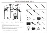
Adjust the hi-hat (VH-10)
1
If you’re using the VH-10 V-hi-hat, execute the oset adjustment from the drum sound module (TD-27) after making connections. This adjustment is required for pedal movements such as open or close to be detected correctly.
Wind the
cable tie
once
Tighten it not to slip
Leave some slack in
the cables
Turn back to x the
cables
Fixing the cables
1. With the hi-hat completely separated from the motion
sensor unit, power-on the TD-27.
Motion sensor unit
Separated
Clutch screw
2. Loosen the clutch screw and let the hi-hat rest
naturally on the motion sensor unit.
3. Press the [SYSTEM] button.
4. Use the cursor buttons to select “TRIGGER,” and press
the [ENTER] button.
5. Use the cursor buttons to select “HI-HAT,” and press the
[ENTER] button.
The TRIGGER HI-HAT screen appears.
6. Use the dial to set the Trig Type to “VH10.”
Adjust the oset.
NOTE
The hi-hat has a correct orientation. Positioning “Roland” logo on the farther
side, as viewed from the player will operate correctly.
NOTE
• Continuous playing may cause dis-coloration of the pad, but
this will not aect the Pad’s function.
• If the hi-hat clutch has been detached from the hi-hat, refer
to “If the Clutch Was Apart from the Hi-Hat” in the “VH-10
Owner’s Manual.”
7. While reading the meter displayed on the right side of the
TD-27’s screen, adjust the oset with the VH-10’s oset
adjustment screw.
Adjust the oset so that the appear in the meter.
OPEN
CLOSE
Oset adjustment screw
Changes
from “ ” to
“
AC
”
8. Fasten the clutch screw so that the hi-hat opens to the amount
you prefer.
9. Press the [DRUM KIT] button to return to the DRUM KIT screen.
If you nd the closed hi-hat sound dicult to play, turn the
oset adjustment screw toward “CLOSE.”
If you nd the open hi-hat sound dicult to play, turn it
toward “OPEN.”
* If the sound is interrupted when you play a strong strike,
adjust the oset adjustment screw toward “OPEN.”
Reference
For details on the hi-hat, refer to “VH-10 Owner’s Manual.”
9
Crash cymbal (CY-16R-T) / (CY-14C-T)
9
Ride cymbal (CY-18DR)
9
Tom (PDA100 / PDA120 / PDA140F)
Reference
For details on the toms, refer to “PDA100/PDA120/PDA140F Owner’s Manual.”
Reference
For details on the cymbals, refer to “CY-16R-T/CY-14C-T Owner’s Manual” or “CY-18DR
Owner’s Manual.”
Adjusting the head tension
NOTE
Continuous playing may cause dis-coloration of the pad, but this will not aect the Pad’s function.
1. Adjust each tuning bolt little by little, across the head as indicated in the
illustration.
Slightly stronger tension than the strike feel of an acoustic drum is appropriate.
2. Make additional ne adjustments to the tension while you continue checking
the feel of the pad’s strike.
* Fully tightening a tension bolt at only a single location will produce uneven tensioning,
which will make it impossible to achieve correct strike response and may also cause
malfunctions.
Fixing the cables
2
1
5
3
4
6
Head
Tuning bolt
NOTE
Adjusting the head tension aects only the head response, and does not change the pitch of the
sound as it would on an acoustic drum.
Pitch adjustments are made by editing the sound in your drum sound module.
Secure the cable in place with
the cable tie
Leave some slack
in the cables
Be sure to make this
small plastic hook
visible from you.
Wind a cable tie
around the pipe and
tighten it in order to
not to slip.
Wind a cable tie around a cable.
Insert the small plastic hook
to a hole to secure the cable
to the cymbal arm.
Used for instructions intended to alert the
user to the risk of injury or material
damage should the unit be used
improperly.
* Material damage refers to damage or
other adverse effects caused with
respect to the home and all its
furnishings, as well to domestic animals
or pets.
Used for instructions intended to alert the
user to the risk of death or severe injury
should the unit be used improperly.
The symbol alerts the user to things that must be
carried out. The specific thing that must be done is
indicated by the design contained within the circle. In the
case of the symbol at left, it means that the power-cord
plug must be unplugged from the outlet.
The symbol alerts the user to important instructions or
warnings.The specific meaning of the symbol is
determined by the design contained within the triangle. In
the case of the symbol at left, it is used for general
cautions, warnings, or alerts to danger.
The symbol alerts the user to items that must never be
carried out (are forbidden). The specific thing that must
not be done is indicated by the design contained within
the circle. In the case of the symbol at left, it means that
the unit must never be disassembled.
About WARNING and CAUTION Notices
About the Symbols
ALWAYS OBSERVE THE FOLLOWING
Additional Precautions
• Use a reasonable amount of care when using the
unit’s buttons, sliders, or other controls; and when
using its jacks and connectors. Rough handling can
lead to malfunctions.
• This instrument is designed to minimize the
extraneous sounds produced when it’s played.
However, since sound vibrations can be transmitted
through oors and walls to a greater degree than
expected, take care not to allow these sounds to
become a nuisance others nearby.
• This document explains the specications of the
product at the time that the document was issued.
For the latest information, refer to the Roland
website.
Intellectual Property Right
• It is forbidden by law to make an audio recording,
video recording, copy or revision of a third party’s
copyrighted work (musical work, video work,
broadcast, live performance, or other work), whether
in whole or in part, and distribute, sell, lease, perform,
or broadcast it without the permission of the
copyright owner.
• Do not use this product for purposes that could
infringe on a copyright held by a third party. We
assume no responsibility whatsoever with regard to
any infringements of third-party copyrights arising
through your use of this product.
• The copyright of content in this product (the sound
waveform data, style data, accompaniment patterns,
phrase data, audio loops and image data) is reserved
by Roland Corporation.
• Purchasers of this product are permitted to utilize
said content (except song data such as Demo
Songs) for the creating, performing, recording and
distributing original musical works.
• Purchasers of this product are NOT permitted to
extract said content in original or modied form, for
the purpose of distributing recorded medium of said
content or making them available on a computer
network.
• The SD logo
and SDHC logo are trademarks
of SD-3C, LLC.
• ASIO is a trademark and software of Steinberg Media
Technologies GmbH.
• This product contains eParts integrated software
platform of eSOL Co.,Ltd. eParts is a trademark of
eSOL Co., Ltd. in Japan.
• The Bluetooth® word mark and logos are registered
trademarks owned by Bluetooth SIG, Inc. and any use
of such marks by Roland is under license.
• This Product uses the Source Code of μT-Kernel under
T-License 2.0 granted by the T-Engine Forum (www.
tron.org).
• Roland and BOSS are either registered trademarks
or trademarks of Roland Corporation in the United
States and/or other countries.
• Company names and product names appearing
in this document are registered trademarks or
trademarks of their respective owners.
USING THE UNIT SAFELY IMPORTANT NOTES