
Pressure-Treated Stair Railing with Aluminum Balusters
INSTALLATION INSTRUCTIONS
ITEMS YOU WILL NEED
• Drill/power screwdriver
• Miter or circular saw with carbide tip blade
• Tape measure
• Carpenter’s level
• Carpenter’s pencil
• Safety glasses/goggles
• Gloves
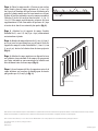
Step 1: Measure the distance between posts and, if necessary,
cut the 2x4 rails to size by trimming the unnotched end. The bal-
uster and rails have been set to 34 degrees, so if you need to cut
the rails and cap rail, cut them to the 34 degree angle (fig.2 ). Cut
the cap rail at the same end as the rails.
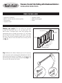
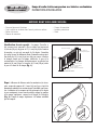
Planning your project: The stair railing was designed
to work on stairs that have a 10” run and 6-3/4” rise,
which creates a 34-degree angle. Check local building code
requirements prior to starting your project. A 6” ball cannot
pass through the triangle formed by the bottom rail, tread
and riser. Stair rails are commonly required to be more than
34” and less than 38” from the tread nose to the top of the
rail (fig. 1).
Railing Brackets (4)
Baluster
Outside Edge of Stairs
Post
Cap
Less than 6"
Less than 4"
Support Block
34" < Tread Nose to
Top of Rail < 38"
Top and
Bottom Rail
•
•
•
•
•
•
•
•
•
•
StairsOutline3a1.ai
g. 1
Cut This End
Do NOT Cut This End
Notch
StairRail1.ai
34°
g. 2

This brochure is for illustration purposes only. Use of this product must be in accordance with all local zoning and/or building codes. Consumer assumes all risks and liability associated with the use of this
product. For details on safe handling and warranty information, go to UFPI.com/ptinfo.
©2013 Universal Forest Products, Inc. All rights reserved. WeatherShield is a registered trademark of Osmose Wood Preserving Company of America.
50415 Herbert Street, P.O. Box 129, Granger, IN 46530
574.277.7670
www.ufpi.com
7188 Stair_7/13
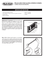
Cap
123 456789101112131415
StairRail2.ai
Insert Rail
•
•
g. 3
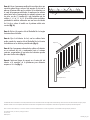
Bottom Rail
Railing Brackets
Balusters
Cap Rail
•
•
•
•
StairRail3.ai
g. 4
Step 2: Place the moulded cap rail upside down on a flat surface.
Next, place the top 2x4 rail with the notch on the same side as the
baluster holes into the moulded cap rail channel so that the holes
are facing up. Starting from either end, fasten the rails together
using the (7) 4” screws through holes 1, 2, 5, 8, 11, 14, 15. If rails are
trimmed, predrill any additional holes with a 1/8” drill bit and insert
the screw into the next nearest hole (fig. 3).
Step 3: Attach the (4) 2x4 DeckoRail railing brackets according to
the included instructions.
Step 4: Attach the bottom 2x4 rail, with the holes facing up, using
the 2x4 DeckoRail railing brackets. Insert the balusters into the pre-
drilled holes (fig. 4).
Step 5: Attach the cap rail by aligning the holes to the baluster
at one end of the rail and working your way to the opposite end,
ensuring that all of the balusters are secured between the two rails
(fig. 4).
Step 6: Fasten a support block at the center of the bottom rail to
the deck surface for spans greater than three feet (fig. 1).
Page is loading ...
Page is loading ...
Page is loading ...

Cette brochure est à titre d’illustration uniquement. Toute utilisation de ce produit doit être conforme aux codes locaux de zonage et/ou du bâtiment. Le consommateur assume tous les risques et respon-
sabilités associés à l’utilisation de ce produit. Pour tous les détails sur le maniement prudent et les informations sur la garantie, rendez-vous sur UFPI.com/ptinfo.
©2013 Universal Forest Products, Inc. Tous droits réservés. WeatherShield est une marque déposée de Osmose Wood Preserving Company of America.
50415 Herbert Street, P.O. Box 129, Granger, IN 46530
574.277.7670
www.ufpi.com
7188 Stair_FR_7/13
rampe supérieure
1 2 3 4 5 6 7 8 9 10 11 12 13 14 15
StairRail2FRENCH.ai
insérez la rampe
•
•
g. 3
Rampe inférieure
Supports de rampe
Balustres
Rampe supérieure
•
•
•
•
StairRail3FRENCH.ai
g. 4
Étape 2 : Placez la rampe moulée à l’envers sur une surface
plane. Ensuite, placez la rampe supérieure de 5,1 cm x 10,2
cm (2 po x 4 po) du même côté que les trous du balustre sur la
gorge de la rampe moulée avec les trous tournés vers le haut.
À partir de l’une des extrémités, serrez les rampes ensemble à
l’aide des (7) vis de 10,2 cm (4 po) dans les trous 1, 2, 5, 8, 11,
14 et 15. Si les rampes sont raccourcies, prépercez des trous
supplémentaires à l’aide d’une mèche de perceuse de 1/8 po
et insérez la vis dans le trou suivant le plus proche (fig. 3).
Étape 3 : Attachez les (4) supports de rampe d’escalier
DeckoRail de 5,1 cm x 10,2 cm (2 po x 4 po) conformément
aux instructions ci-jointes.
Étape 4 : Attachez la rampe inférieure de 5,1 cm x 10,2 cm (2
po x 4 po) avec les trous faisant face vers le haut, à l’aide des
supports de rampe d’escalier DeckoRail de 5,1 cm x 10,2 cm
(2 po x 4 po). Insérez les balustres dans les trous prépercés
(fig. 4).
Étape 5 : Attachez la rampe supérieure en alignant les trous
sur le balustre à une extrémité de la rampe et en progressant
vers l’autre extrémité en vous assurant que les balustres sont
fixés solidement entre les deux rampes (fig. 4).
Étape 6 : Serrez fermement le bloc de support au centre de la
rampe inférieure sur la surface de platelage pour les travées
plus grandes que 91,5 cm (3 pi) (fig. 1).
-
 1
1
-
 2
2
-
 3
3
-
 4
4
-
 5
5
-
 6
6


Ask a question and I''ll find the answer in the document
Finding information in a document is now easier with AI
in other languages
- français: DeckoRail 172977 Guide d'installation
- español: DeckoRail 172977 Guía de instalación
Related papers
-
Unbranded 287872 Installation guide
-
DeckoRail 287872 FAQ
-
DeckoRail 71998 Installation guide
-
DeckoRail 58670 FAQ
-
-
-
-
-
-
Other documents
-
 Belknap Hill Trading Post 188399 Installation guide
-
 Veranda ArmorGuard CAPC NE 5 MT BLK Installation guide
-
 Veranda RLC 6 CC 3PK Installation guide
-
Deckorators 408512 Installation guide
-
 Veranda BALC 36 NG 5PK Installation guide
-
-
-
RDI 73019122 Installation guide
-
none 191578 Installation guide
-
 Veranda SEC14 EWS R13 KD Installation guide


