Antaira Industrial Ethernet Switches
LMP-0600 Series User Manual V1.0
i
LMP-0600 Series
6-Port Industrial PoE+ Managed Ethernet Switches
4*10/100Tx (30W/Port), 2*10/100Tx, 48~55VDC Power Input
User Manual
Version 1.0

Antaira Industrial Ethernet Switches
LMP-0600 Series User Manual V1.0
ii
© Copyright 2014 Antaira Technologies, LLC
All Rights Reserved
This document contains information, which is protected by copyright. Reproduction, adaptation or translation
without prior permission is prohibited, except as allowed under the copyright laws.
Trademark Information
Antaira is a registered trademark of Antaira Technologies, LLC, Microsoft Windows and the Windows logo are the
trademarks of Microsoft Corp. NetWare is the registered trademark of Novell Inc. WMM and WPA are the
registered trademarks of Wi-Fi Alliance. All other brand and product names are trademarks or registered
trademarks of their respective owners.
Notice: Copyrights © 2014 by Antaira Technologies, LLC. All rights reserved. Reproduction, adaptation, or
translation without prior permission of Antaira Technologies, LLC is prohibited, except as allowed under the
copyright laws.
Disclaimer
Antaira Technologies, LLC provides this manual without warranty of any kind, expressed or implied, including but
not limited to the implied warranties of merchantability and fitness for a particular purpose. Antaira Technologies,
LLC may make improvements and/or changes to the product and/or specifications of the product described in this
manual, without prior notice. Antaira Technologies, LLC will not be liable for any technical inaccuracies or
typographical errors found in this guide. Changes are periodically made to the information contained herein and
will be incorporated into later versions of the manual. The information contained is subject to change without prior
notice.

Antaira Industrial Ethernet Switches
LMP-0600 Series User Manual V1.0
iii
FCC Warning
This equipment has been tested and found to comply with the limits for a Class-A digital device, pursuant to Part
15 of the FCC rules. These limits are designed to provide reasonable protection against harmful interference in a
residential installation. This equipment generates, uses, and can radiate radio frequency energy. It may cause
harmful interference to radio communications if the equipment is not installed and used in accordance with the
instructions. However, there is no guarantee that interference will not occur in a particular installation. If this
equipment does cause harmful interference to radio or television reception, which can be determined by turning
the equipment off and on, the user is encouraged to try to correct the interference by one or more of the following
measures:
Reorient or relocate the receiving antenna.
Increase the separation between the equipment and receiver.
Connect the equipment into an outlet on a circuit different from that to which the receiver is connected.
Consult the dealer or an experienced radio/TV technician for help.
Caution: Any changes or modifications not expressly approved by the grantee of this device could void the user's
authority to operate the equipment.
CE Mark Warning
This is a Class-A product. In a domestic environment this product may cause radio interference in which case the
user may be required to take adequate measures.
Industrial Ethernet Switches
Industrial Grade Gigabit Unmanaged Ethernet Switches
User Manual
Version 1.0 (September 2014)
This manual supports the following models:
LMP-0600
LMP-0600-T
This document is the current official release manual. Please check our website (www.antaira.com) for any
updated manual or contact us by e-mail ([email protected]).

Antaira Industrial Ethernet Switches
LMP-0600 Series User Manual V1.0
iv
Table of Contents
1. Introduction................................................................................................ 1
1.1 Product Overview .......................................................................... 1
1.2 Product Software Features ............................................................ 1
1.3 Product Hardware Features ........................................................... 2
1.4 Package Contents ......................................................................... 2
1.5 Safety Precaution .......................................................................... 3
2. Hardware Description ............................................................................... 4
2.1 Physical Dimensions… .................................................................. 4
2.2 Front Panel………………………………………………………………5
2.3 Top View ........................................................................................ 5
2.4 LED Indicators ............................................................................... 6
2.5 Ethernet Ports ................................................................................ 6
2.6 Cabling .......................................................................................... 8
2.7 Wiring the Power Inputs................................................................. 8
2.8 Wiring the Fault Alarm Contact ...................................................... 9
3. Mounting Installation ............................................................................... 10
3.1 DIN-Rail Mounting ........................................................................ 10
3.2 Wall Mounting .............................................................................. 11
4. Hardware Installation ............................................................................... 12
4.1 Installation Steps .......................................................................... 12
5. Web Management .................................................................................... 13
5.1 Web Console Configuration ......................................................... 13
5.1.1 About Web-based Management ............................................ 13
5.2 Basic Setting ................................................................................ 14
5.2.1 System Information ................................................................ 14
5.2.2 Admin &Password .................................................................. 15
5.2.3 IP Setting ............................................................................... 16
5.2.4 System Time .......................................................................... 17
5.3 Port Management ........................................................................ 18

Antaira Industrial Ethernet Switches
LMP-0600 Series User Manual V1.0
v
5.3.1 Port Status ............................................................................. 18
5.3.2 Port Configuration .................................................................. 18
5.4 PoE (Power-over-Ethernet) ......................................................... 19
5.4.1 PoE Configuration .................................................................. 19
5.4.2 Ping Alarm ............................................................................. 20
5.4.3 PoE Schedule ........................................................................ 21
5.5 ERPS ........................................................................................... 22
5.5.1 ERPS Status .......................................................................... 23
5.5.2 ERPS Configuration ............................................................... 23
5.6 Spanning Tree ............................................................................. 30
5.6.1 RSTP Status .......................................................................... 31
5.6.2 RSTP Configuration ............................................................... 31
5.6.3 MSTI Status ........................................................................... 33
5.6.4 MSTI Configuration ................................................................ 34
5.7. 802.1Q VLAN ............................................................................. 36
5.7.1 802.1Q VLAN Settings ........................................................... 36
5.7.2 802.1Q VLAN Settings ........................................................... 37
5.8. IGMP Snooping .......................................................................... 37
5.8.1 IGMP Settings ........................................................................ 38
5.8.2 IGMP Snooping Status Table ................................................. 39
5.9 QoS (Traffic Prioritization) ........................................................... 39
5.9.1 QoS Classification .................................................................. 40
5.9.2 CoS Mapping ......................................................................... 41
5.9.3 ToS Mapping .......................................................................... 42
5.10 Port Mirroring ............................................................................. 43
5.11 SNMP……… .............................................................................. 44

Antaira Industrial Ethernet Switches
LMP-0600 Series User Manual V1.0
vi
5.11.1 SNMP Agent ......................................................................... 44
5.11.2 SNMP Trap setting ............................................................... 45
5.12 System Warning ......................................................................... 46
5.12.1 Syslog Setting ...................................................................... 46
5.12.2 System Event Log ................................................................ 47
5.12.3 SMTP Setting ....................................................................... 48
5.12.4 Event Selection .................................................................... 49
5.12.5 Fault Alarm… ....................................................................... 49
5.13 MAC Table…. ............................................................................ 50
5.13.1 MAC Address Table ............................................................. 50
5.13.2 MAC Table Configuration..................................................... 50
5.14 Maintenance .............................................................................. 51
5.14.1 Upgrade ............................................................................... 51
5.14.2 Reboot ................................................................................. 52
5.14.3 Default .................................................................................. 52
5.15 Configuration .............................................................................. 52
5.15.1 Save……….. ........................................................................ 53
5.15.2 Backup & Store .................................................................... 53
5.15.3 Auto Load & Backup ............................................................ 54
5.16 Logout……… ............................................................................. 54
6. Command Line Interface Management .................................................. 55
6.1 About CLI Management ............................................................ 55
7. Technical Specifications ......................................................................... 72

Antaira Industrial Ethernet Switches
LMP-0600 Series User Manual V1.0
1
1. Introduction
All Antaira industrial managed switches come with a pre-installed “user friendly” web console interface,
which allows users to easily configure and manage the units, whether one is using a serial console
and command line interface(CLI) commands like Telnet, SSH, HTTP (Web GUI) or simple network
management protocols (SNMP).
1.1 Product Overview
Antaira’s LMP-0600 series is a 6-port industrial PoE+ managed Ethernet switch that is IEEE
802.3at complaint (power-over-Ethernet plus), and is embedded with four 10/100Tx Ethernet
ports that support either IEEE802.3af or IEEE802.3at for a maximum of 30 watts per port, and two
10/100Tx Fast Ethernet ports. It is a fully manageable industrial Ethernet switch that supports the
standard Layer 2 Ethernet configurable settings. This product series is IP30 rated and DIN-rail
mountable that provides a standard operating temperature range (-10°C to 70°C) and an
extended operating temperature range (-40°C to 75°C). It also designed with high EFT and ESD
protection to prevent any unregulated voltage for industrial networking applications in process
control automation, intelligent transportation systems (ITS), power/utility, water wastewater
treatment plants, any outdoor or harsh environment.
1.2 Product Software Features
Network Redundancy
STP, RSTP, MSTP, ITU-T G.8032 Ethernet Ring Protection Switch (ERPS) for
network redundancy
Network Management
Web UI based management, SNMP v1/v2, serial console
Qos, traffic classification QoS, Cos, bandwidth control for Ingress and Egress,
broadcast storm control, Diffserv
IEEE802.1q VLAN, port-based VLAN support
IGMP snooping v1/v2, IGMP filtering / throttling, IGMP query up to 256 group
Supports RMON, MIB II, port mirroring, event syslog, DNS, NTP/SNTP, SSH/SSL,
TFTP
Advanced PoE Ports Management (Auto Ping Check)
Auto powered device (PD) detection

Antaira Industrial Ethernet Switches
LMP-0600 Series User Manual V1.0
2
Auto reset (cycle power to unresponsive PD)
PoE ports weekly power scheduling
Port Configuration
Status, statistics, mirroring, rate limiting, event syslog
Event Handling
Event notification by email: cold/warm start, power failure, authentication, SNMP trap
and fault alarm relay output
Software Upgrade via TFTP and HTTP
Configuration Backup – USB Port
1.3 Product Hardware Features
System Interface and Performance
All RJ-45 ports support auto MDI/MDI-X function
Embedded 4*10/100Tx (PSE 30W/Port) RJ45 Ports, and 2*10/100Tx Fast Ethernet ports
Store-and-forward switching architecture
8K MAC address table
Power line EFT protection: 2,000VDC; Ethernet ESD protection: 6,000VDC
Power Input
DC 48~55V redundant with a 6-pin removal terminal block
One user programmable alarm relay contact
Operating Temperature
Standard operating temperature models: -10°C to 70°C
Extended operating temperature models: -40°C to 75°C
Case/Installation
IP-30 protection metal housing
Installation in pollution degree to environment
DIN-Rail and wall mount design
1.4 Package Contents
1– LMP-0600 series: 6-port industrial PoE+ managed Ethernet switch, with 4*10/100Tx
(30W/Port) RJ45 Ports, and 2*10/100Tx Fast Ethernet ports.
1-Product CD
2-Wall mounting brackets and screws
1-RJ45 to DB9 Serial Console Cable

Antaira Industrial Ethernet Switches
LMP-0600 Series User Manual V1.0
3
1-DC cable –18 AWG & DC jack 5.5x2.1mm
1.5 Safety Precaution
Attention: If the DC voltage is supplied by an external circuit, please use a protection
device on the power supply input. The industrial Ethernet switch’s
hardware specs, ports, cabling information, and wiring installation will be
described within this user manual.

Antaira Industrial Ethernet Switches
LMP-0600 Series User Manual V1.0
4
2. Hardware Description
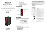
2.1 Physical Dimensions
Figure 2.1, below, shows the physical dimensions of Antaira’s LMP-0600 series: 6-port industrial
PoE+ managed Ethernet switch with 4*10/100Tx (30W/Port) RJ45 ports, and 2*10/100Tx RJ45
ports.
(W x D x H) is 46mm x 99mm x 142mm
Figure2.1
LMP-0600 Series Physical Dimensions

Antaira Industrial Ethernet Switches
LMP-0600 Series User Manual V1.0
5
2.2 Front Panel
The front panel of the LMP-0600 series industrial
PoE+ managed Ethernet
switch is shown below in
Figure 2.2.
2.3 Top View
Figure 2.3, below, shows the top panel of the LMP-0600 series switch that is equipped with
one 6-pin removal terminal block connector for dual DC power inputs (48~55VDC).
Figure2.2
The Front Panel of LMP-0600 Series
Figure2.3
Top Panel View of LMP-0600 Series

Antaira Industrial Ethernet Switches
LMP-0600 Series User Manual V1.0
6
2.4 LED Indicators
There are LED light indicators located on the front panel of the industrial Ethernet switch that
display the power status and network status. Each LED indicator has a different color and has
its own specific meaning, see below in Table 2.1.
LED
Color
Description
P1
Green
On
Powerinput1is active
Off
Powerinput1isinactive
P2
Green
On
Powerinput2is active
Off
Powerinput2isinactive
Fault
Green
On
System is ready
Off
System is booting
Red
On
Fault Alarm
Off
System is in normal state
LAN Port 1~ 6
(Left LED)
Green
On
Connected to network, 10/100Mbps
Flashing
Networking is active
Off
Not connected to network
LAN Port 1~ 4
(Right LED)
PoE Indicators
Green
On
The port is supplying power to the powered-device
Off
No powered-device attached or power supplying fails
2.5 Ethernet Ports
RJ-45 Ports
RJ-45 Ports (Auto MDI/MDIX): The RJ-45 ports are auto-sensing for 10Base-T, 100Base-TX
connections. Auto MDI/MDIX means that the switch can connect to another switch or workstation
without changing the straight-through or crossover cabling. See the figures below for straight-
through and crossover cabling schematics.
Table 2.1
LED Indicators for LMP-0600 Series

Antaira Industrial Ethernet Switches
LMP-0600 Series User Manual V1.0
7
RJ-45 Pin Assignments (Table 2.2)
Pin Number
Assignment
1
Rx+
2
Rx-
3
Tx+
6
Tx-
All ports on this industrial Ethernet switch support automatic MDI/MDI-X operation. Users can
use straight-through cables (see figure below) for all network connections to PCs, servers, other
switches or hubs. With straight-through, cable pins 1, 2, 3, and 6, at one end of the cable are
connected straight through to pins 1, 2, 3 and 6 at the other end of the cable. The table below
(Table 2.3) shows the 10BASE-T, 100BASE-TX MDI and MDI-X port pin outs.
The following figures show the cabling schematics for straight-through and crossover.
Figure 2.4 Figure 2.5
Straight-Through Cable Schematic Crossover Cable Schematic
Note
“+” and “-” signs represent the polarity of the wires that make up each wire pair.
Pin MDI-X
Signal Name
MDI Signal Name
1
Receive Data plus (RD+)
Transmit Data plus (TD+)
2
Receive Data minus (RD-)
Transmit Data minus (TD-)
3
Transmit Data plus (TD+)
Receive Data plus (RD+)
6
Transmit Data minus (TD-)
Receive Data minus (RD-)
Table 2.2
RJ45 Pin Assignments
Table 2.3
Ethernet Signal Pin Outs

Antaira Industrial Ethernet Switches
LMP-0600 Series User Manual V1.0
8
2.6 Cabling
Twisted-pair segments can be connected with an unshielded twisted pair (UTP) or shielded
twisted pair (STP) cable. The cable must comply with the IEEE 802.3u 100Base TX
standard (e.g. Category 5, 5e, or 6). The cable between the equipment and the link partner
(switch, hub, workstation, etc.) must be less than 100 meters (328 ft.) long.
Fiber segments using a single-mode connector type must use a 9/125μm single-mode
fiber cable.
Fiber segments using a multi-mode connector type must use a 50 or 62.5/125 μm multi-
mode fiber cable.
2.7 Wiring the Power Inputs
Please follow the steps below to insert the power wire.
1. Insert the positive and negative wires into the PWR1 (V1+, V1-) and PWR2 (V2+, V2-)
contacts on the terminal block connector as shown below in Figure 2.6.
2. Tighten the wire-clamp screws to prevent the wires from loosening, as shown below in Figure
2.7.
Note
Only use copper conductors, 60/75°C, tighten to 5lbs.
The wire gauge for the terminal block should range between 18~20 AWG.
Figure 2.7
Power Terminal Block
Figure 2.6
Power Terminal Block

Antaira Industrial Ethernet Switches
LMP-0600 Series User Manual V1.0
9
2.8 Wiring the Fault Alarm Contact
The fault alarm contact is in the middle of the terminal block connector as the picture shows below
in Figure 2.8. By inserting the wires, it will detect the fault status including power failure or port link
failure (managed industrial switch only) and forma normally open circuit. An application example
for the fault alarm contact is shown below in Figure 2.8.
Note
The wire gauge for the terminal block should range between 12 ~ 24AWG
Figure 2.8
Wiring the Fault Alarm Contact

Antaira Industrial Ethernet Switches
LMP-0600 Series User Manual V1.0
10
3. Mounting Installation
3.1 DIN-Rail Mounting
The DIN-Rail is pre-installed on the
industrial Ethernet switch from the factory.
If the DIN-Rail is not on the industrial
Ethernet switch, please see Figure 3.1 to
learn how to install the DIN-Rail on the
switch.
Follow the steps below to learn how to hang the industrial Ethernet switch.
1. Use the screws to install the DIN-Rail bracket on the rear side of the industrial Ethernet switch.
2. To remove the DIN-Rail bracket, do the opposite from step 1.
3. After the DIN-Rail bracket is installed on the rear side of the switch, insert the top of the DIN-
Rail on to the track as shown below in Figure 3.2.
4. Lightly pull down the bracket on to the rail as shown below in Figure 3.3.
5. Check if the bracket is mounted tightly on the rail.
6. To remove the industrial
Ethernet
switch from the rail, do the opposite from the above steps.
Figure 3.1
The Rear Side of the Switch and DIN-Rail Bracket
Figure 3.3
Stable the Switch on DIN-Rail
Figure 3.2
Insert the Switch on the DIN-Rail

Antaira Industrial Ethernet Switches
LMP-0600 Series User Manual V1.0
11
3.2 Wall Mounting
Follow the steps below to mount the industrial
Ethernet
switch using the wall mounting bracket as
shown below in Figure 3.4.
1. Remove the DIN-Rail bracket from the industrial Ethernet switch by loosening the screws.
2. Place the wall mounting brackets on the top and bottom of the industrial Ethernet switch.
3. Use the screws to screw the wall mounting bracket on the industrial Ethernet switch.
4. Use the hook holes at the corners of the wall mounting bracket to hang the industrial Ethernet
switch on the wall.
5. To remove the wall mount bracket, do the opposite from the steps above.
Below, in Figure 3.5 are the dimensions of the wall mounting bracket.
Figure 3.5
Wall Mounting Bracket Dimensions
Figure 3.4
Remove DIN-Rail Bracket from the Switch

Antaira Industrial Ethernet Switches
LMP-0600 Series User Manual V1.0
12
4. Hardware Installation
4.1 Installation Steps
This section will explain how to install Antaira’s LMP-0600 series: 6-port industrial PoE+ managed
Ethernet switch with 4*10/100Tx (30W/Port) RJ45 ports and 2*10/100Tx RJ45 ports.
Installation Steps
1. Unpack the industrial Ethernet switch from the original packing box.
2. Check if the DIN-Rail bracket is screwed onto the industrial Ethernet switch.
If the DIN-Rail is not screwed on the industrial Ethernet switch, please refer to the
DIN-Rail Mounting section for DIN-Rail installation.
If you want to wall mount the industrial Ethernet switch, please refer to the Wall
Mounting section for wall mounting installation.
3. To hang the industrial Ethernet switch on a DIN-Rail or wall, please refer to the Mounting
Installation section.
4. Power on the industrial Ethernet switch and then the power LED light will turn on.
If you need help on how to wire power, please refer to the Wiring the Power Inputs
section.
Please refer to the LED Indicators section for LED light indication.
5. Prepare the twisted-pair, straight-through category 5 cable for Ethernet connection.
6. Insert one side of the RJ-45 cable into switch’s Ethernet port and on the other side into the
networking device’s Ethernet port, e.g. switch PC or server. The Ethernet port’s (RJ-45) LED
on the industrial Ethernet switch will turn on when the cable is connected to the networking
device.
Please refer to the LED Indicators section for LED light indication.
7. When all connections are set and the LED lights all show normal, the installation is complete.

Antaira Industrial Ethernet Switches
LMP-0600 Series User Manual V1.0
13
5. Web Management
5.1 Web Console Configuration
This section introduces the configuration by web browser.
5.1.1 About Web-Based Management
All of Antaira’s industrial managed switches are embedded with HTML web console interfaces
that have a flash memory on the CPU board. It is a “user friendly” design with advanced
management features that allow users to manage the switch from anywhere on the network
through any Internet browser, such as Internet Explorer (version 9.0 or above is recommended),
Firefox, Chrome and many others.
Preparing for Web Console Configuration
Antaira’s industrial managed switches come with a factory default value as below:
Default IP Address: 192.168.1.254
Default User Name: admin
Default Password: admin
System Login
1. Launch any Internet browser
2. Type in factory default IP address: http://192.168.1.254 of the switch. Press “Enter”.
Figure 5.1 - Web Console “Login”

Antaira Industrial Ethernet Switches
LMP-0600 Series User Manual V1.0
14
3. The login screen appears
4. Key in the default username: admin and password: admin
5. Click “Login” button, then the main (status) page of the web console will appear as below in
Figure 5.2. The online image of the switch will display the real-time ports connection status.
5.2 Basic Setting
5.2.1 System Information
Below, Figure 5.3, shows the switch system setting information.
Figure 5.2
Web Console Main (Status) Page
Figure 5.3 – Switch Settings (Status) Page
Page is loading ...
Page is loading ...
Page is loading ...
Page is loading ...
Page is loading ...
Page is loading ...
Page is loading ...
Page is loading ...
Page is loading ...
Page is loading ...
Page is loading ...
Page is loading ...
Page is loading ...
Page is loading ...
Page is loading ...
Page is loading ...
Page is loading ...
Page is loading ...
Page is loading ...
Page is loading ...
Page is loading ...
Page is loading ...
Page is loading ...
Page is loading ...
Page is loading ...
Page is loading ...
Page is loading ...
Page is loading ...
Page is loading ...
Page is loading ...
Page is loading ...
Page is loading ...
Page is loading ...
Page is loading ...
Page is loading ...
Page is loading ...
Page is loading ...
Page is loading ...
Page is loading ...
Page is loading ...
Page is loading ...
Page is loading ...
Page is loading ...
Page is loading ...
Page is loading ...
Page is loading ...
Page is loading ...
Page is loading ...
Page is loading ...
Page is loading ...
Page is loading ...
Page is loading ...
Page is loading ...
Page is loading ...
Page is loading ...
Page is loading ...
Page is loading ...
Page is loading ...
Page is loading ...
/