ANTAIRA LMP-0600-V2 Series User guide
- Category
- Network switches
- Type
- User guide
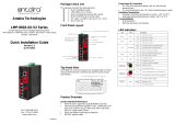
ANTAIRA LMP-0600-V2 Series is a 6-Port Industrial PoE+ Managed Ethernet Switch with 410/100Tx (30W/Port) and 210/100Tx ports.
This device provides advanced networking capabilities and is designed for harsh industrial environments. It features dual DC power inputs for redundancy and an IP30 protection rating, making it suitable for use in demanding applications where reliability is crucial.
With its PoE+ capabilities, the ANTAIRA LMP-0600-V2 Series can power connected devices such as IP cameras, VoIP phones, and wireless access points, eliminating the need for separate power supplies.
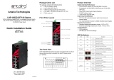
The switch's front panel includes LED indicators for power, fault, link/activity status, and PoE status, providing real-time visibility into the device's operation.
ANTAIRA LMP-0600-V2 Series is a 6-Port Industrial PoE+ Managed Ethernet Switch with 410/100Tx (30W/Port) and 210/100Tx ports.
This device provides advanced networking capabilities and is designed for harsh industrial environments. It features dual DC power inputs for redundancy and an IP30 protection rating, making it suitable for use in demanding applications where reliability is crucial.
With its PoE+ capabilities, the ANTAIRA LMP-0600-V2 Series can power connected devices such as IP cameras, VoIP phones, and wireless access points, eliminating the need for separate power supplies.
The switch's front panel includes LED indicators for power, fault, link/activity status, and PoE status, providing real-time visibility into the device's operation.


-
 1
1
-
 2
2


ANTAIRA LMP-0600-V2 Series User guide
- Category
- Network switches
- Type
- User guide
ANTAIRA LMP-0600-V2 Series is a 6-Port Industrial PoE+ Managed Ethernet Switch with 410/100Tx (30W/Port) and 210/100Tx ports.
This device provides advanced networking capabilities and is designed for harsh industrial environments. It features dual DC power inputs for redundancy and an IP30 protection rating, making it suitable for use in demanding applications where reliability is crucial.
With its PoE+ capabilities, the ANTAIRA LMP-0600-V2 Series can power connected devices such as IP cameras, VoIP phones, and wireless access points, eliminating the need for separate power supplies.
The switch's front panel includes LED indicators for power, fault, link/activity status, and PoE status, providing real-time visibility into the device's operation.
Ask a question and I''ll find the answer in the document
Finding information in a document is now easier with AI
Related papers
-
 ANTAIRA LMP-0602-XX-V2 Series Installation guide
-
ANTAIRA LMP-1202M-SFP-24 Installation guide
-
 ANTAIRA LMX-1202M-SFP series Installation guide
-
ANTAIRA LMX-0802 Series Installation guide
-
ANTAIRA LMX-0800 Series Installation guide
-
ANTAIRA LNP-0702C-SFP-24 Series Installation guide
-
ANTAIRA LNX-0702C-SFP Series Installation guide
-
ANTAIRA LMP-0800G Series Installation guide
-
ANTAIRA LNP-1204G-SFP Series Installation guide
-
 ANTAIRA LNP-1002G-SFP-24 Installation guide


