Page is loading ...

DS400 & DS500
Digital Fishfinders
Owner’s Handbook
Document number: 81234-1
Date: December 2003


DS400 and DS500 Digital Fishfinders iii
Preface
This handbook describes the Raymarine DS400 and DS500 Digital
Fishfinders.
Conventions Used
Throughout this handbook, the labelled keys are shown in bold capitals; for
example, MENU. The software menu names and options are shown in
normal capitals; for example, AUTOMATIC.
Operating procedures, which may consist of a single key-press or a sequence
of numbered steps, are indicated by a ➤ symbol in the margin.
Technical Accuracy
The technical and graphical information contained in this handbook, to the
best of our knowledge, was correct as it went to press. However, the
Raymarine policy of continuous improvement and updating may change
product specifications without prior notice. As a result, unavoidable
differences between the product and handbook may occur from time to time,
for which liability cannot be accepted by Raymarine.
Warranty
To register your DS400/500 Digital Fishfinder ownership, please take a few
minutes to fill out the warranty registration card found at the end of this
handbook. It is very important that you complete the owner information and
return the card to the factory in order to receive full warranty benefits.

iv DS400 and DS500 Digital Fishfinders
Important Information
This handbook contains important information on the installation and
operation of your new equipment. In order to obtain the best results in
operation and performance, please read this handbook thoroughly.
Raymarine’s Product Support representatives, or your authorized dealer, are
available to answer any questions you may have.
Intended Use
Raymarine DS400 and DS500 Digital Fishfinders are intended for
recreational fishfinding.
EMC Conformance
All Raymarine equipment and accessories are designed to the best industry
standards for use in the recreational marine environment.
Their design and manufacture conforms to the appropriate Electromagnetic
Compatibility (EMC) standards, but correct installation is required to ensure
that performance is not compromised. Although every effort has been taken
to ensure that they will perform under all conditions, it is important to
understand what factors could affect the operation of the product.
The guidelines given here describe the conditions for optimum EMC
performance, but it is recognized that it may not be possible to meet all of
these conditions in all situations. To ensure the best possible conditions for
EMC performance within the constraints imposed by any location, always
ensure the maximum separation possible between different items of
electrical equipment.
For optimum EMC performance, it is recommended that wherever
possible:
• Raymarine equipment and cables connected to it are:
• At least 3 ft (1 m) from any equipment transmitting or cables carrying
radio signals, e.g., VHF radios, cables and antennas.
• More than 7 ft (2 m) from the path of a radar beam. A radar beam can nor-
mally be assumed to spread 20 degrees above and below the radiating ele-
ment.

DS400 and DS500 Digital Fishfinders v
• Raymarine specified cables are used. Cutting and rejoining these cables
can compromise EMC performance and must be avoided unless doing so
is detailed in the installation manual.
• If a suppression ferrite is attached to a cable, this ferrite should not be
removed. If the ferrite needs to be removed during installation it must be
reassembled in the same position.
Safety Notices
1. PRODUCT INSTALLATION. This equipment must be installed and
operated in accordance with the instructions contained in this handbook.
Failure to do so could result in poor product performance, personal injury
and/or damage to your boat.
2. HIGH VOLTAGE. The display unit, transducer cable, and transducer
contain high voltages. Adjustments require specialized service procedures
and tools only available to qualified service technicians - there are no user
serviceable parts or adjustments.
3. NAVIGATION AID. This unit is only an aid to navigation. Its accuracy
can be affected by many factors, including equipment failure or defects,
environmental conditions, and improper handling or use. It is the user’s
responsibility to exercise common prudence and navigational judgments.
This fishfinder should not be relied upon as a substitute for such prudence
and judgment.
4. ULTRASONIC ENERGY. The transducer transmits high frequency
energy while in use. The unit should be turned off when swimmers or divers
are in close proximity to the transducer. (There is a lack of scientifically
sound standards or guidelines for exposure levels and limits to ultrasound.
This notice is precautionary only.)
WARNING:
Do not disconnect the transducer cable without first powering off the
display unit. Removal of the transducer cable from the DS400/500 while
power is turned on can cause sparks.
Mount unit where it is well ventilated and free from gasoline fumes.

vi DS400 and DS500 Digital Fishfinders
Raymarine Products and Services
Raymarine products are supported by a network of Authorized Service
Representatives. Raymarine’s Technical Services representatives or your
local dealer will be available to answer any questions you may have. For
information on Raymarine products and services, contact either of the
following:
United States Raymarine, Incorporated
22 Cotton Road, Unit D
Nashua, New Hampshire
03063-4219 USA
Telephone:1-603-881-5200
1-800-539-5539
Fax: 1-603-864-4756
Europe Raymarine Limited
Anchorage Park
Portsmouth, Hampshire
PO3 5TD England
Telephone: +44 (0) 23 9269 3611
Fax: +44 (0) 23 9269 4642
Or, you may contact us on the World Wide Web at:
www.raymarine.com
© Raymarine Limited 2003

vii
Contents
Preface ................................................................................................................... iii
Important Information ........................................................................................iv
Chapter 1: Overview ............................................................................................1
1.1 Introduction ...................................................................................... 1
Features ......................................................................................... 2
General .......................................................................................... 2
Transducer .............................................................................. 3
Chapter 2: Installation .........................................................................................5
2.1 Introduction ...................................................................................... 5
Planning the Installation ............................................................... 5
Suppression Ferrites ............................................................... 5
Connections to Other Equipment ............................................ 5
2.2 Unpacking and Inspecting the Components ..................................... 6
2.3 Selecting the Equipment Location ................................................... 7
Mounting Location ....................................................................... 7
2.4 Cable Runs ....................................................................................... 8
2.5 Mounting the Fishfinder ................................................................. 11
Bracket Mounting ....................................................................... 11
Console Mounting (optional) ..................................................... 11
2.6 System Connections ....................................................................... 13
DC Power Connection ................................................................ 13
Transducer Connection ............................................................... 14
2.7 Installing the E66062 (P58) Transducer ......................................... 16
Applications ................................................................................ 16
Tools and Materials ..................................................................... 16
Pretest ......................................................................................... 17
Mounting Location ..................................................................... 17
Installation .................................................................................. 18
Checking for Leaks ..................................................................... 23
Operation and Maintenance ........................................................ 24
Releasing the transducer ....................................................... 24
Antifouling Paint .................................................................. 24
Cleaning ................................................................................ 24
Servicing the Paddlewheel .................................................... 24

viii DS400 and DS500 Digital Fishfinders
Chapter 3: Getting Started ................................................................................27
3.1 Introduction ....................................................................................27
3.2 Powering on the Fishfinder ............................................................ 27
3.3 Simulator Mode .............................................................................. 27
3.4 LCD Display .................................................................................. 28
3.5 Keypad Operation .......................................................................... 30
3.6 Selecting the Display Page ............................................................ 31
3.7 Main Menu ..................................................................................... 33
Selecting MENU Items ............................................................... 34
3.8 Interpreting and Adjusting the Sounder Image .............................. 37
Fish Indications ........................................................................... 38
Effect of Frequency and Boat Speed ..................................... 38
3.9 Using the Variable Range Marker (VRM) ...................................... 39
Chapter 4: Menu Operation ...............................................................................41
4.1 Introduction ....................................................................................41
4.2 Fishfinder Operation Controls ........................................................42
Scroll Speed ................................................................................ 43
Range .......................................................................................... 43
Hunt Mode ............................................................................ 45
Frequency ................................................................................... 45
A-Scope ...................................................................................... 46
GAIN MODE... .......................................................................... 47
GAIN .................................................................................... 48
Color Gain ............................................................................. 49
Time Variable Gain (TVG) ................................................... 49
Sounder Interference Rejection (Int. Rej.) ............................ 49
Second Echo Rejection ......................................................... 50
Power .................................................................................... 50
Max. Ping Rate ...................................................................... 50
ZOOM... ..................................................................................... 51
View ...................................................................................... 51
Zoom x2, x3, x4 Magnification ............................................. 52
Mode ..................................................................................... 52
TRIP RESET... ............................................................................ 53
DISPLAY SET UP... ................................................................... 53
SOUNDER SET UP... ................................................................. 53
Chapter 5: Display Controls ..............................................................................55
5.1 Introduction ....................................................................................55
5.2 DISPLAY SET UP... ....................................................................... 55
Brightness ................................................................................... 58
Target Depth ID .......................................................................... 58
Depth Digit Size .......................................................................... 59

ix
Transparent Menu ....................................................................... 59
PALETTE... ................................................................................ 59
Selection ............................................................................... 59
Background Color ................................................................. 59
DATA ITEMS... .......................................................................... 60
NAV. SET UP... (Navigation Data) ............................................. 61
Chapter 6: Sounder Setup ..................................................................................63
6.1 Introduction .................................................................................... 63
6.2 SOUNDER SETUP... ..................................................................... 63
ALARMS... ................................................................................ 67
Target Depth ID .................................................................... 68
Fish Alarm ............................................................................ 68
Shallow Alarm ...................................................................... 68
Shallow Range ...................................................................... 68
Deep Alarm ........................................................................... 68
Deep Range ........................................................................... 69
Temp. Alarm ......................................................................... 69
Temp. Rng. High ................................................................... 69
Temp. Rng. Low ................................................................... 69
ALARM CLOCK... .............................................................. 70
UNITS... ..................................................................................... 71
Depth Units ........................................................................... 71
Temp. Units ........................................................................... 71
Speed Units ........................................................................... 71
Distance Units ....................................................................... 71
Bearing Mode ....................................................................... 71
Date Format .......................................................................... 71
Time Format .......................................................................... 72
NMEA-OUT SET UP... .............................................................. 72
Language .................................................................................... 73
Key Beep .................................................................................... 73
Key Help ..................................................................................... 73
Depth Offset ................................................................................ 73
Speed Calibrate ........................................................................... 74
Temp Calibrate ............................................................................ 74
Sounder Simulator ...................................................................... 74
SW Version and Serial Number (read only) ................................ 74
Chapter 7: Maintenance and Problem Solving ...............................................75
7.1 Maintenance ................................................................................... 75
Routine Checks ........................................................................... 75
Cleaning Instructions .................................................................. 75
EMC Servicing and Safety Guidelines ....................................... 76

x DS400 and DS500 Digital Fishfinders
7.2 Problem Solving ............................................................................. 77
Common Problems and Their Solutions ..................................... 77
7.3 How to Contact Raymarine ............................................................ 78
On the Internet ............................................................................ 78
Customer Support ................................................................. 78
In the US ..................................................................................... 78
Accessories and Parts ............................................................ 78
Technical Support .................................................................79
Product Repair and Service ................................................... 79
In Europe ..................................................................................... 80
Technical Support .................................................................80
Accessories and Parts ............................................................ 80
Worldwide Support ..................................................................... 80
Appendix A:Specifications .................................................................................81
Index ..................................................................................................83

Chapter 1: Overview 1
Chapter 1: Overview
1.1 Introduction
This handbook describes the DS400 and DS500 Digital Fishfinders. The
DS400/DS500 feature state-of-the-art High Definition Fish Imaging (HDFI)
technology. Constantly adjusting transmitter and receiver parameters, the
DS400/DS500 intelligently analyzes fish and bottom echoes and
automatically produces a crystal clear echo sounder display.
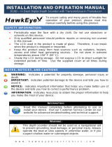
Figure 1-1: DS400 Digital Fishfinder
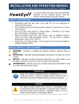
Figure 1-2: DS500 Digital Fishfinder
D6437-1
D6445-1

2 DS400 and DS500 Digital Fishfinders
The DS400/500 employs a very high transmission repetition or “ping” rate
which, along with the digital adaptive high sample rate receiver, ensures that
fish and bottom structure are presented in superb detail and optimal color
allocation. The DS400/500 digital bandwidth adaptation adjusts the receiver
band width dynamically from very wide to very narrow, as required by the
actual water conditions. This provides superior fish and bottom detection in
conditions where other fishfinders see very little or nothing at all.
Features
• DS500: 5" Transmissive High Brightness TFT Color LCD
DS400: 3.5" Transflective Daylight Viewable TFT Color LCD
•¼ VGA 76,800 Pixel Display Resolution
• Patented Digital HDFI Technology
• Hands-Off Adaptive Auto Adjustments
• Dual Frequency 200/50 kHz 500W RMS
• Depth/Temp/Speed transducer included with some models, which can
measure water depth, water temperature and speed
• Speedometer-style digital data screen overlay
• NMEA 0183 compliant
• Easy Bracket or Flush mounting
• Waterproof to IPX7
General
The DS400/500 system, illustrated below, is comprised of the digital
fishfinder, transducer and associated cables.
The DS400/500 is waterproof to IPX7 and can be installed either above or
below deck.
The unit includes connections to:
• Power/NMEA
• the transducer

Chapter 1: Overview 3
Figure 1-3: Basic Fishfinder System using the DS400/500
Transducer
The DS400/500 requires a transducer for measuring water depth, water
temperature, distance traveled, and speed. A transducer is included with
some fishfinder models. It is important to position your transducer correctly.
Details on your transducer, including location and installation instructions,
are included in the transducer box.
Note: Instructions for mounting the E66062 (P58) Multisensor Transom
Mount Transducer is not included with the transducer. Installation instruc-
tions for this transducer can be found on page 16.
Transducer
Fishfinder
D6451-1

4 DS400 and DS500 Digital Fishfinders

Chapter 2: Installation 5
Chapter 2: Installation
2.1 Introduction
This chapter provides installation instructions for your DS400/500.
Note: If you wish to practice using the unit before installation, connect the
power cable and use the simulator mode as described in Chapter 3. For pow-
er, connect a 12VDC power supply, attaching the red wire to positive and the
black wire to negative. See Section 3.3 for details.
Planning the Installation
Before you install your system, plan the installation, considering:
• Location of the fishfinder, as described in Section 2.3
• Cable Runs, as described in Section 2.4.
Suppression Ferrites
The following illustration shows typical cable suppression ferrites used with
Raymarine equipment. Always use the ferrites supplied by Raymarine.
Figure 2-1: Typical Suppression Ferrites
Connections to Other Equipment
If your Raymarine equipment is to be connected to other equipment using a
cable not supplied by Raymarine, a suppression ferrite must always be
attached to the cable that is closest to the Raymarine unit.

6 DS400 and DS500 Digital Fishfinders
2.2 Unpacking and Inspecting the Components
Unpack your system carefully, to prevent damage to the equipment. Save the
carton and packing, in case you need to return a unit for service.
Check that you have all the correct system components. These depend on
your system package, as follows:
Transducers are supplied with some models and optional with others. The
following transducer options are available:
1
supplied with some models
Table 2-1: Parts and Accessories
Item
Part
No.
Supplied /
Option
One of the following units:
DS400 Digital Fishfinder without Transducer, US version
DS400 Digital Fishfinder without Transducer, CE version
DS500 Digital Fishfinder without Transducer, US version
DS500 Digital Fishfinder without Transducer, CE version
E63061
E63062
E63063
E63064
supplied
supplied
supplied
supplied
Sun Cover, DS400
Sun Cover, DS500
R69070
R69071
supplied
supplied
Mounting Bracket, DS400
Mounting Bracket, DS500
R69072
R69075
supplied
supplied
Mounting Bracket Knobs, DS400, DS500 R69073 supplied
Power/NMEA cable R69074 supplied
Handbook, DS400/500 81234 supplied
Mounting hardware N/A supplied
Flush Mount Kit, DS400
Flush Mount Kit, DS500
E66067
E66068
optional
Table 2-2: Transducer Options
Item Part No. Option
Transducer Adapter Cable for L365/L470 Style Transducers E66070 option
Transducer Adapter Cable for hsb
2
/DSM250 Style Transducers
E66066 option
Transom Mount Transducer for DS400/DS500 (P58) E66062
varies
1
Bronze Thru-hull Transducer or DS400/DS500 (B744V) E66061
varies
1

Chapter 2: Installation 7
2.3 Selecting the Equipment Location
Mounting Location
The DS400/500 is waterproof to IPX7 is and designed to be mounted either
above or below deck. The unit should be protected from physical damage and
excessive vibration.
CAUTION:
Mount the DS400/500 in a protected area away from prolonged
exposure to rain, salt spray, and direct sunlight, but well ventilated.
When planning the installation, the following should be considered to ensure
reliable and trouble free operation:
• Access: There must be sufficient space below the unit to enable cable
connections to the panel connectors, avoiding tight bends in the cable.
• Interference: The selected location should be far enough away from
devices that may cause interference, such as motors, generators, and
radio transmitter/receivers (see the EMC guidelines earlier in this sec-
tion).
• Magnetic compass: Mount the unit at least 3 ft (1m) away from a mag-
netic compass.
• Cable runs: The unit must be located near a DC power source. The
power cable supplied is 5 ft (1.5 m), but a longer cable can be used if
desired. Refer to Section 2.4.
The maximum length of cable between the fishfinder and the transducer
unit should not normally exceed 25 ft (8 m). If you need to use a longer
cable, refer to Section 2.4.
• Environment: Good ventilation is required to prevent the unit from
overheating.
WARNING:
Removal of the transducer cable from the DS400/500 while power is
turned on can cause sparks. As with any electronic device, be sure the
fishfinder is mounted where it is well ventilated and free from gasoline
fumes.

8 DS400 and DS500 Digital Fishfinders
2.4 Cable Runs
Consider the following before installing the system cables:
• You will need to attach the power and transducer cables.
• All cables should be adequately secured, protected from physical dam-
age, and protected from exposure to heat.
Avoid running cables through bilges or doorways, or close to moving or
hot objects.
• Sharp bends must be avoided.
• Where a cable passes through an exposed bulkhead or deckhead, a water-
tight feed-through should be used.
• Secure cables in place using tie-wraps or lacing twine. Coil any extra
cable and tie it out of the way.
You will need to run the following cables:
• Power/NMEA cable, supplied with the unit. This 5 ft (1.5 m) cable has
a connector plug at one end for connecting to the fishfinder, and 3 wires at
the other end for connecting the power supply. The power cable may be
extended by up to 60 ft (20 m) using a wire gauge of AWG 12 or greater.
The DS400/500 is intended for use on the boat’s DC power systems
rated from 10-18 Volts DC (13.8V nominal).
• Transducer cable, supplied with the transducer. This 25 ft (8 m) cable
has a connector plug (with an outer nut that you must attach) at one end
for the display unit or extension cable. The transducer cable may be
extended up to a maximum of 60 ft (20 m) using optional extension
cables.
Cutting the transducer cable will severely reduce sonar performance:
• Do not cut the transducer cable or remove the connector.
• Do not shorten or splice the cable.
If the cable is cut, it must be replaced—it cannot be repaired.
Cutting the cable will also void the warranty.

Chapter 2: Installation 9
Figure 2-2: DS400 Unit Dimensions
2.28 in
(57.9 mm)
5.88 in
(149.4 mm)
5.12 in
(130 mm)
4.45 in
(113 mm)
5.0 in
(127 mm)
3.17 in
(80.5 mm)
1.3 in
(33.2 mm)
2.70 in
(68.6 mm)
2.99 in
(76 mm)
2.83 in
(72 mm)
3.46 in
(88 mm)
D6440-1
2.28 in
(57.9 mm)

10 DS400 and DS500 Digital Fishfinders
Figure 2-3: DS500 Unit Dimensions
3.46 in
(88 mm)
5.88 in
(149.4 mm)
2.66 in
(67.6 mm)
3.08 in
(78.3 mm)
2.99 in
(76 mm)
2.83
(72
m
6.37 in
(161.8 mm)
3.81 in
(96.7 mm)
5.9 in
(150 mm)
6.22 in
(158 mm)
D6448-1
2.66 in
(67.6 mm)
1.68 in
(42.7 mm)
/