Page is loading ...

1
ELECTRO MEDICAL SYSTEMS
AirFlow
®
S1
Service manual
AirFlow
®
S1
Water
Airflow

2
AirFlow
®
S1

3
AirFlow
®
S1
Table of contents
Important note 5
The unit and its components 6
Installation 6
Technical data 7
Description of the unit 7
Description of the electrical parts 8
Description of the hydraulic parts 10
Description of the pneumatic parts 11
Description of the powder parts 12
Trouble shooting 14
Verication of the general condition (internal) 14
Verication of the primary electrical circuit 14
Verication of the secondary electrical circuit 14
Verication of the water circuit 14
Verication of the air circuit 16
Verication of the powder circuit 16
Opening of the unit 15
Disconnecting of the air, water and powder hoses 16
Replacement of the secondary fuses 17
Unsoldering of the electrical wires 17
Replacement of the primary fuses 18
Assembly of the knob 19
Replacement of the transformer 20
Replacement of the thermostats 21
Replacement of the water heater 22
Procedure in case of heating problem 23
Replacement of the water lter cartridge 24
Replacement of the complete water lter 24
Replacement of the water regulator 25
Replacement of the pneumatic module for polisher 26
Replacement of the air lter element 27
Replacement of the air lters 27
Replacement of the electrovalve 28
Replacement of the air regulator 29
Replacement of the powder bowl set 30
Replacement of the pinch valve 31
Spare parts & Update 32
Spair part View 33-35
Function control 36
Safety control 36
EMS reserves the right to modify the technic, accessories, operating instructions or
the contents of the AirFlow
®
S1 due to technical or scientic improvements.

4
AirFlow
®
S1

5
Important note
As manufacturer of electrical/medical devices, our responsibility
extends to the technical safety features of the unit only if mainte-
nance, repairs and modications are carried out by a repair center
trained and authorized by EMS.
All repairs or revisions must be carried out with the original EMS
spare parts.
The EMS quality policy requires a function control for each inter-
vention and a safety control for each intervention requiring the
opening of the unit.
Each intervention of units for repair or revision must be docu-
mented.
For each return addressed to EMS, please clean and disinfect the
AirFlow
®
as described in the operating instructions and sterilize
the handpiece.
The boards must be wrapped in an antistatic bag.
This unit may not be operated in an explosion hazardous environ-
ment.
AirFlow
®
S1

6
AirFlow
®
S1
The unit and its components
Installation
Mains 100 - 110 V AC
Water
Airow
AirFlow
®
S1
Footswitch
Mains 220 - 240 V AC
Water pressure
1 - 5 bar
Compressed air
4.5 - 7 bar
Polisher handpiece
Spanner for water lter
Installation
The following connections are required to operate the
unit :
A water supply of between 1 and 5 bars
A compressed air supply of between 4.5 and 7 bars
An electrical supply.

7
Technical data
Description of the unit
The powder unit of the AirFlow
®
S1 is primarily intented for remov-
ing soft deposits and discolourations from all visible areas of teeth
as well as from ssures and interdental spaces.
The AirFlow
®
S1 is driven by a pneumatic footswitch.
7
Technical data
Description of the unit
The powder unit of the AirFlow
®
S1 is primarily intented for removing
soft deposits and discolourations from all visible areas of teeth as well
as from ssures and interdental spaces.
The AirFlow
®
S1 is driven by a pneumatic footswitch.
Description of the electrical parts
Manufacturer: EMS SA - 1260 Nyon, Switzerland
Models: AirFlow
®
S1
Classication: EN 60601-1 Class I
Type B
IP 20
93/42 CEE: Class IIa
Mode of operation: Continuous operation
Supply voltage: 100 V AC / 110 V AC
220 V AC
240 V AC
Main frequency: 50 - 60 Hz
Power consumption: max. 75 VA / for CSA units 115 VA*
Fuses Primary: ø 5 x 20 mm, 250 V
for 100V AC/110V AC, T 1 A, time-lag
for 220V AC/240V AC, T 0.5 A, time-lag
Secondary: ø 5 x 20 mm, 250 V, T 2.5A, time-lag
Compressed air supply: 4.5 to 7 bar (450 to 700 kPa) >15 Nl/min
(66 to 102 Psi)
Water supply: Cold water 1 to 5 bar (100 to 500 kPa)
(15 - 73 Psi)
Operating conditions: +10
o
C to +40
o
C (+50F to 104F)
30% to 75% relative humidity
Storage and transport
conditions: -10
o
C to +40
o
C (+14F to 104F)
10% to 95% relative humidity
Air pressure: 500 hPa to 1060 hPa
Weight: Approx. 3.6 kg (8.1 lbs)
Dimensions: Height: 120 mm
Width: 250 mm
Length: 250 mm
* For units sold in the USA and Canada

8
AirFlow
®
S1
Description of the electrical parts
This unit is equipped with a mains socket with fuses incor-
porated. The main switch ON/OFF is placed on the back
side of the unit.
The mains voltage (high voltage of 110, 220 or 240 V AC)
is converted into 24V AC (low voltage), by an internal trans-
former, to supply all the electrical components of the unit.
Mains socket
and primary fuses
Main switch
Secondary fuse
Transformer
Water heater
Electrovalve
Thermostat 60°C
Thermostat 47°C

9
AirFlow
®
S1
Primary circuit (high voltage)
*For the transformers without thermal protection (no pin 1), connect the black wire on pin 2.
Secondary circuit (low voltage)
Blue
24 V AC
Green LED
Resistance
+-
Electrovalve
Blue
Blue
Blue
Blue
Blue
Thermostat
Red
47˚C
Thermostat
60˚C
Red
Water heater
Green/Ye llow
Red
Red Red
Red
Red
Red
Black
Secondary fuse
T 2.5A
Transformer
*
Main switch
Mains socket
T 1A
Primary fuses
T 1A
Ye llow/
Green
ON/OFF
11
1
2
4
3
5
6 240 V
130 V
220 V
110 V
8
9
Red
Black
Secondary fuse
T 2.5A
Transformer
*
Main switch
Mains socket
Ye llow/
Green
ON/OFF
11
1
2
4
3
5
6 240 V
130 V
220 V
110 V
8
9
Red
Black
Secondary fuse
T 2.5A
Transformer
*
Main switch
Mains socket
Ye llow/
Green
ON/OFF
11
1
2
4
3
5
6 240 V
130 V
220 V
110 V
8
9
110 V AC
220 V AC
240 V AC
Red
Red
Red
Red
Red
Black
Black
Black
T 0.5A
Primary fuses
T 0.5A
T 0.5A
Primary fuses
T 0.5A
Blue
24 V AC
Red
Blue
Red
Blue
24 V AC
Red
Blue
Red
Blue
24 V AC
Red
Blue
Red
Ye llow/Green
Ye llow/Green
Ye llow/Green
Ye llow/Green
Ye llow/Green
Ye llow/Green

10
AirFlow
®
S1
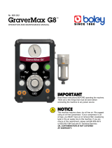
Description of the hydraulic parts
AirFlow
®
S1 is equipped with a water lter at the entrance
of the water supply. Water circuit is made by blue hoses.
On the AirFlow
®
unit, the water passes through a water
lter then though a water regulator allowing the regulation
of the ow, and goes into the pneumatic module driven by
the electrovalve, the heater and the polisher handpiece via
the handpiece cord.
Polisher handpiece
Water regulator
Pneumatic module for
polisher
Water heater
Water lter
Water supply
Polisher
handpiece cord
Additional connections available for AirFlow
®
S2
Water filter on
AirFlow
®
S1
Water filter on
AirFlow
®
S2
Pneumatic
module for
polisher
Water heater
Polisher
connector
Polisher handpiece
Scaler
handpiece cord
Pneumatic
module for
scaler
Scaler
connector
Scaler handpiece
Water
regulator
Water
regulator

11
Description of the pneumatic parts
AirFlow
®
S1 unit is driven by a pneumatic footswitch. Internal air
circuit is made by yellow hoses.
It is equipped with an air lter at the entrance of the air supply.
The air passes through a regulator allowing the regulation of the
ow, and goes into the a set of two air lters before its entrance
into the powder bowl.
The pneumatic module for polisher, the pinch valve and the water
circuit are driven by the air circuit.
AirFlow
®
S1
Footswitch
Air lter
Electrovalve
Powder bowl set
Pinch valve
Pneumatic module
for polisher
Air regulator
Air supply
See water circuit
Pneumatic module for polisher
Electrovalve
Pinch valve
Footswitch
Powder bowl set
Air filterAir filterAir filter
Air regulator

12
AirFlow
®
S1
Description of the powder parts
The powder circuit is used on the AirFlow
®
system. The
powder circuit is made by a transparent hose.
The powder comes from the powder bowl and passes
through the pinch valve allowing the stop of the ow, and
goes into the polisher handpiece via the handpiece cord.
Polisher
handpiece cord
Powder bowl set
Pinch valve
Polisher
connector
Polisher handpiece
Polisher handpiece
Polisher connector
Pinch valve
Powder bowl set
Polisher handpiece cord

13
Notes
Remarks and observations

14
AirFlow
®
S1
Trouble shooting
* Replacement do not need the opening of the unit
-
-
°
°
≤ ≤
≤ ≤
≤ ≤
≤ ≤

15
Opening of the unit
Remove the screw (83) and open the upper casing by
lifting up from the closed position.
The assembly of the upper part and the lower part of the
unit is made by the hinge (86).
83
86

16
AirFlow
®
S1
* Replacement do not need the opening of the unit
Disconnecting of the air, water and powder hoses
In all cases, remove rst the external collar and after the
conical part of the uniclamp (92).
Remove the hose (66, 70 or 85) from the tubing of the ele-
ment.
66
70
85
92
1616
1616
16

17
Unsoldering of the electricawires
In all cases, before to unsolder the wires on the
electrical connexion, remove the insulated sleeving.
Replacement of the secondary fuse
Turn the fuse holder head (82) on the anticlockwise and
extract the fuse (81).
Replace the fuse following the specications mentioned
on the sticker.
FUSE
T
2.5
AMPS
82
81
Sticker
Insulated sleeving
Connector

18
AirFlow
®
S1
Replacement of the primary fuses
Open the unit (see page 15).
Apply a lateral slight pressure with a small screwdriver on
the fuse holder (78) and extract the fuses (77).
Replace the fuses following the specications mentioned
on the sticker at the rear of the unit.
FUSES
100-110V
T 1 A
220-240V
T 500mA L
I
O
78
Sticker
77

19
Assembly of the knob
The regulators and taps sent for After Sales Support
are ADJUSTED and TESTED to function correctly.
Don’t modify the adjustment before assembly.
Preparation of the regulator holder
Cut the three external pins coming from the moulding.
Lay down a lm of silicone paste on the contact surface
between the knob and the holder.
Assembly instructions
Put the knob (68) and the elastic washer (69) into the knob
holder of the regulator in such a way that the stop of the
knob is as close as possible to the stop of the knob holder
(on the left). Do not turn the axis of the regulator. The knob
should be able to turn in a clockwise direction (thus open-
ing the regulator).
Turn the knob anticlockwise (0
o
-15
o
) to join the 2 stops. The
regulator is now at minimum position.
Put the assembly into the upper casing of the unit (from
inside), the spot of the knob should be opposite to the spot
on the casing .
69
Stop on the knob
Stop on the regulator
holder
Silicone paste
Regulator axis
68
Spot of the knob
Spot on the casing

20
AirFlow
®
S1
Replacement of the transformer
Remove the three screws (90) of the metal housing of the
transformer (64).
Remove the housing of the transformer and extract the
bushing (93).
Remark: note the order of connection for each wire.
Unsolder all the electrical cables of the transformer (65).
Remove the four screws (83) and the washers (74) of the
transformer.
Put in place a new transformer.
90
64
93
65
83
74
/