Page is loading ...

MN-772 • (071708) • ECR 8900
For maximum effectiveness and safety,
please read these instructions completely
before proceeding with installation.
Failure to read these instructions can result
in an incorrect installation.
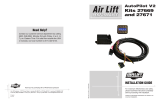
INSTALLATION GUIDE
Gen 3
Kit 72000
Automatic Leveling Digital
On-Board Compressor System
Advanced Integrated Remote
WirelessAIR


TABLE OF CONTENTS
Introduction .......................................2
System Information .................................................2
Important Safety Notice .............................................2
Hardware & Tools Lists ..............................3
Installation Diagram ................................4
Installation Schematics. . . . . . . . . . . . . . . . . . . . . . . . . . . . . . 6
Electrical Schematic ................................................6
Pneumatic Schematic ...............................................7
Installing the WirelessAIR System .....................8
Recommended Compressor Locations ..................................8
Installing the Compressor ............................................8
Installing the Manifold ...............................................8
Installing the Harness ...............................................9
Attaching the Air Lines ...............................................9
Checking the System. . . . . . . . . . . . . . . . . . . . . . . . . . . . . . . . . . . . . . . . . . . . . . . .10
General System Description ..........................................10
Controller Description ...............................................10
Icon Denition .....................................................11
System Operation ..................................12
Sleep Mode .......................................................12
Normal Mode ......................................................12
Settings Mode .....................................................15
Joining the Controller to the Manifold ...................................16
Quick Function Reference ............................................17
Important: Avoiding Cold Weather Freeze-up .......... 18
Templates .........................................19
Limited Warranty and Return Policy ...................21
Replacement Information ............................21
Contact Information ................................21

2
MN-772
WirelessAIR
Introduction
The purpose of this publication is to assist with the installation, maintenance and
troubleshooting of the WirelessAIR System.
It is important to read and understand the entire installation guide before beginning installation
or performing any maintenance, service or repair. The information here includes a hardware
list, step-by-step installation information, safety information and a troubleshooting guide.
Air Lift Company reserves the right to make changes and improvements to its products and
publications at any time. Contact Air Lift Company at (800) 248-0892 for the latest version
of this manual.
SYSTEM INFORMATION
WirelessAIR is designed for automatic digital leveling of the on-board compressor system.
The kit includes a compressor, manifold, wiring harness, and wireless digital controller. The
system can be used in or outside the vehicle, for adjustments in full view of the vehicle.
The wireless digital controller is a compact, battery-powered unit. It also includes a clip that
can be attached to the vehicle’s visor. Three user-dened memory settings are provided
for frequently used settings. As an added safety measure, minimum air pressures are
automatically maintained. The manifold is also weather-resistant for maximum life expectancy.
IMPORTANT SAFETY NOTICE
The installation of this kit does not alter the gross vehicle weight rating (GVWR) or payload
of the vehicle. Check your vehicle’s owner’s manual and do not exceed the maximum load
listed for your vehicle.
Gross Vehicle Weight Rating: The maximum allowable weight of the fully loaded vehicle
(including passengers and cargo). This number — along with other weight limits, as well
as tire, rim size and ination pressure data — is shown on the vehicle’s Safety Compliance
Certication Label.
Payload: The combined, maximum allowable weight of cargo and passengers that the truck
is designed to carry. Payload is GVWR minus the base curb weight.
NOTATION EXPLANATION
Hazard notations appear in various locations in this publication. Information which is highlighted
by one of these notations must be observed to help minimize risk of personal injury or possible
improper installation which may render the vehicle unsafe. Notes are used to help emphasize
areas of procedural importance and provide helpful suggestions. The following denitions explain
the use of these notations as they appear throughout this guide.
INDICATES IMMEDIATE HAZARDS WHICH WILL RESULT IN SEVERE PERSONAL INJURY
OR DEATH.
INDICATES HAZARDS OR UNSAFE PRACTICES WHICH COULD RESULT IN SEVERE
PERSONAL INJURY OR DEATH.
INDICATES HAZARDS OR UNSAFE PRACTICES WHICH COULD RESULT IN DAMAGE TO
THE MACHINE OR MINOR PERSONAL INJURY.
DANGER
CAUTION
WARNING

3
MN-772
WirelessAIR
TOOLS LIST
Description ...........................................Qty
Hoist or oor jacks ............................................ 1
Safety stands .................................................... 2
Safety glasses .................................................. 1
Heavy duty drill ................................................. 1
#2 Phillips bit driver .......................................... 1
Description ...........................................Qty
7/32” & 1/4” Drill bits ........................................ 1
5/16” Driver ...................................................... 1
Hose cutter ....................................................... 1
Spray bottle with dish soap/water solution ....... 1
Digital volt meter ............................................... 1
Missing or damaged parts? Call Air Lift customer
service at (800) 248-0892 for a replacement part.
STOP!
HARDWARE LIST
Item Part # Description................................Qty
A 26558 Manifold ..............................................1
B 73002 Display ................................................1
C 10928 Battery, AAA ........................................3
D 26514 Electrical Harness ...............................1
E 16092 12V Compressor with Filter .................1
Hardware Pack
F 21839 1/8” MNPT-1/4” PTC ..........................1
G 21240 1/8” FNPT - Barbed Fitting .................1
H 20946 Air Line, 1/4” (DOT Approved)........20 ft
I 11060 Gen 3 Wireless Bracket ......................1
J 17173 #14-1/4 X 3/4” Self-tapping Screw ......2
K 17428 #10-24 X 3/8” Machine Screw ............2
Item Part # Description................................Qty
L 24661 Heat Shrink Butt Splice 14-16 ga ........ 1
M 24752 Heat Shrink Butt Splice 10-12 ga ........ 1
N 24539 Fuse Holder ........................................1
O 24652 Fuse, Spade - 15AMP .........................1
P 24524 Female Spade Terminal 3/16” ............1
Q 24595 Female Spade Terminal 12 awg .........1
R 24561 Mini Fuse Adapter ...............................1
S 24542 Fuse Tap Adapter ................................ 1
T 10466 Zip Tie ................................................15
U 21838 T-Fitting ...............................................2
V 17273 Self-tapping Screw .............................. 4
W 24681 Terminal Ring 3/8” ..............................1
Hardware and Tools Lists

4
MN-772
WirelessAIR
Relay Schematic Reference:
8787
8585
8686
3030
Ignition
PWR
Compressor
Signal from
Manifold
Compressor
PWR
Existing Fuse
REAR
N
M
O
P or Q
R or S
(Attach to un-fused side of Ignition Powered Auxiliary Fuse)
U
U
G
H
E
AL004
F
AL007
L
Compressor
Filter
15 AMP Fuse
A
For Reference Only
Not included in kit
Compressor
Relay
Filter
Compressor
Ground
RIGHT
LEFT
H
Join Input
NOTE: Air Lift recommends
using a sharp knife or
hose-cutting tool to ensure a
proper cut.
If a hose connection has
been disconnected, the hose
must be trimmed 1/2” back
to provide for a leak-free
seal.
* Inflation valves are provided with
the base kit and are intended to be
used for emergency inflation.
*
*
+
-
To Battery Ground
Fused Ignition
Fused Ignition
Fuse Adapter Schematic:
Fuse Box
Ignition Wire
Fuse Adapter
In Line
15 amp Fuse
Adapter #1
Adapter #2 *
* Uses 3/16 (smaller) Female Push On Connector
Adapter
Fuse
Fuse Adapter Options:
Must be 2.5’ long

5
MN-772
WirelessAIR
Installation Diagram
g. 1
Relay Schematic Reference:
8787
8585
8686
3030
Ignition
PWR
Compressor
Signal from
Manifold
Compressor
PWR
Existing Fuse
REAR
N
M
O
P or Q
R or S
(Attach to un-fused side of Ignition Powered Auxiliary Fuse)
U
U
G
H
E
AL004
F
AL007
L
Compressor
Filter
15 AMP Fuse
A
For Reference Only
Not included in kit
Compressor
Relay
Filter
Compressor
Ground
RIGHT
LEFT
H
Join Input
NOTE: Air Lift recommends
using a sharp knife or
hose-cutting tool to ensure a
proper cut.
If a hose connection has
been disconnected, the hose
must be trimmed 1/2” back
to provide for a leak-free
seal.
* Inflation valves are provided with
the base kit and are intended to be
used for emergency inflation.
*
*
+
-
To Battery Ground
Fused Ignition
Fused Ignition
Fuse Adapter Schematic:
Fuse Box
Ignition Wire
Fuse Adapter
In Line
15 amp Fuse
Adapter #1
Adapter #2 *
* Uses 3/16 (smaller) Female Push On Connector
Adapter
Fuse
Fuse Adapter Options:
Must be 2.5’ long
g. 2

6
MN-772
WirelessAIR
Installation - Electrical Schematic
g. 3
AL004 (PK-18GA) Ignition
Circuit
Number
Wire
Color
Wire
Size
Circuit
Function
(1st & Last Letter)
AL004 (RD-10GA) IGNITION
AL006 (GY-16GA) COMP SIG
AL004 (RD-16GA) IGNITION
AL004 (RD-10GA) IGNITION
AL007 (RD/WE-12GA) COMP PWR
IGNITION SOURCE
15A
FRAME GROUND
AL012 (YW-16GA) SYNC INPUT
AL004 (PK-16GA) IGNITION
AL005 (BK-16GA) GROUND
AL006 (GY-16GA) COMP SIG
-
+
VEHICLE
BATTERY

7
MN-772
WirelessAIR
(Left)
(Right)
Schrader Valve
Schrader Valve
Installation - Pneumatic Schematic
g. 4

8
MN-772
WirelessAIR
RECOMMENDED COMPRESSOR LOCATIONS
Important
LOCATE COMPRESSOR IN DRY, PROTECTED AREA ON VEHICLE.
DIRECT SPLASH OR EXCESSIVE MOISTURE CAN DAMAGE
THE COMPRESSOR AND CAUSE SYSTEM FAILURE.
Disclaimer: If you choose to mount the compressor outside the vehicle, please keep in mind
that the compressor body must be shielded from direct splash, and the intake should be
snorkeled inside the vehicle. If the compressor does not include a remote mount air lter or
if mounting the compressor outside the vehicle, make sure to orient the compressor intake
lter so that all moisture can easily drain.
Please also remember...
• To avoid high-heat environments (including engine bay and exhaust).
• The compressor can be mounted in any position — vertical, upside down, sideways, etc.
• Compressors ingest moisture and will deposit water inside the system. In sub 0
degrees F(18 C) environments this water may freeze and require the addition of air
brake antifreeze (see page 18).
INSTALLING THE COMPRESSOR
1. Select a rigid mounting location for the compressor on the vehicles frame or cross
member (g. 1) that shields the compressor from the elements and heat sources.
The compressor must be no more than 24” (610mm) away from he manifold. Do not extend
the wires.
2. Use the supplied compressor fasteners to fasten the compressor to the frame or cross
member.
3. Use the supplied self-tapping fasteners (V) if installing on a boxed frame.
• One of the screws will be used as an electrical ground for the compressor terminal.
• Another of the screws can be used to mount the compressor relay.
On thick frame sections, it may be necessary to drill a pilot hole for the self-tap fasteners.
INSTALLING THE MANIFOLD
This manifold has a lter attached. The lter has to be oriented correctly to function properly
(g. 5). This is an automatic draining lter and does not need servicing. If you nd this lter
to be plugged, it will need to be replaced.
Installing the WirelessAIR System
NOTE
NOTE
Do not install
inverted or
angled.
Top view of lter and manifold
g. 5

9
MN-772
WirelessAIR
In order to mount the manifold/lter assembly correctly so the lter can drain properly, it may
be necessary to rotate the lter on the manifold to orient it correctly (g. 1).
1. Select a rigid mounting location for the manifold (A) on the vehicle’s frame or cross
member that shields the manifold from the elements and heat sources (g. 1).
2. Use mounting bracket 11060 (I) and secure to the rigid mounting surface with 17173
fasteners (J). Please refer to the “Manifold Mounting” diagram.
Locate manifold above compressor if possible.
Some vehicles have high radio/electronic interference and require manifold to be mounted
close to driver.
INSTALLING THE HARNESS
1. Connect electrical connector to manifold (A).
a. Push down until fully seated.
b. Push red secondary lock down.
2. Connect compressor to harness.
a. Cut off terminal on compressor red wire.
b. Strip 1/4”(7mm) insulation off compressor red wire.
c. Crimp on weatherproof blue butt splice (L) to compressor red wire.
d. Crimp on weatherproof blue butt splice (L) to harness pink wire
AL007 (RD/WE-12GA).
e. Heat butt splice to seal connection.
f. Connect compressor ground wire ring terminal and relay to vehicle ground (g. 1).
• Using one of the self-tapping screws for the compressor, you can attach all
the components to the vehicle frame ground.
g. Connect the black wire “ground to battery” to the negative battery terminal.
3. Connect the AL004 circuit to the vehicle ignition.
a. Route the AL004 (RD-10GA) wire to a 15A ignition source.
• Cut off the excess wire length if all is not needed.
b. Strip off 1/4” (7mm) of insulation off both sides of the inline fuse holder (N) and
the AL004 (RD-10GA) wire.
c. Crimp on the weatherproof yellow butt splice (M) to AL004 (RD-10GA) wire.
d. Crimp on the weatherproof yellow butt splice (M) to one side of the inline fuse holder.
• Heat butt splice to seal connection.
e. Select the appropriate type of fuse tap in terminal for your application (g. 1).
f. Crimp on the correct terminal that mates with the appropriate type of fuse tap in
terminal for your application (P or Q).
g. Connect the terminal to the inline fuse holder (N).
h. Install fuse (O).
ATTACHING THE AIR LINES
1. Manifold Filter to Compressor
a. Cut a section of DOT 1/4” hose (H) to the necessary length to reach from the
compressor leader hose to the tting on the lter attached to the manifold (g. 4).
Length of hose must be 2 1/2’ (.76m) long for lter to work properly. Coil up hose and zip
tie it to something if necessary.
b. Remove the air line compression nut from the compressor leader hose.
c. Insert the hose through the compression nut and onto the barbed tting of the
leader hose, and tighten down the compression nut.
d. Route and insert into the tting on the lter attached to the manifold port “C” PTC
(Push To Connect).
2. Manifold to Air Springs
a. Cut a section of hose (H) and route from the manifold port 1 to the previously
installed LEFT spring ination hose.
i. Cut the ination hose at an accessible location and insert the T-Fitting (U).
NOTE
NOTE

10
MN-772
WirelessAIR
M1 M2 DN UP
NAV
PAD
GENERAL SYSTEM DESCRIPTION
The WirelessAIR control system is designed to control two air springs independently. The
control system is composed of a manifold, compressor, controller, and plug-n-play harness.
The manifold will maintain the desired pressure in the air springs within 3 PSI (.21BAR) by
exhausting or activating the compressor as needed. The controller is used to change the
desired pressure of the manifold and view the status of the system.
CONTROLLER DESCRIPTION
The controller has buttons M1 and M2 for controlling presets, UP and DN buttons that adjust
the spring pressure, the NAV PAD that is used to select and control many different options,
and the LCD to display pressures and other information to the user.
WirelessAir Controller buttons
g. 6
ii. Insert the hose from manifold port 1 to left spring ination T-Fitting.
b. Cut a section of hose (H) and route from the manifold port 2 to the previously
installed RIGHT spring ination hose.
i. Cut the ination hose at an accessible location and insert T-Fitting (U).
ii. Insert hose from manifold port 2 to right spring ination T-Fitting.
CHECKING THE SYSTEM
1. Pressurize the system to check for leaks.
2. Inspect all air line connections with a solution of dish soap and water. If a leak is detected
in a push-lock-tting, cut the hose end square and reinstall the air line to the tting.
Make sure the air line is cut off squarely and that the air line is completely pushed into
the tting.
3. If the compressor or the solenoid fails to function, check the 15-amp fuse and ground
connection. Repair and replace as necessary.

11
MN-772
WirelessAIR
The controller has an LCD to provide the user feedback for system operation. This LCD
will display air spring pressures, provide status of the system and display fault detection
messages.
Controller LCD
ICON DEFINITION
Battery is displayed when the battery voltage in the controller is low, a
low-battery voltage may prohibit a high-strength wireless transmission
and may result in a failed transmission.
Transmission indicator is displayed when the controller is actively
communicating with the manifold.
Fail indicator is displayed when this is a failure of the system for example,
communication failure, valve blockage or a leak.
Compressor indicator is displayed when the compressor is running and
the system is lling an air spring to the desired pressure.
Unit of measure will be indicated per the user setup.
Exhaust arrow will be displayed when the manifold exhaust valve is active
and the system is exhausting an air spring to the desired pressure.
Accessory icon will be active in the settings mode.
g. 7

12
MN-772
WirelessAIR
SLEEP MODE
The controller features a sleep mode to preserve battery life. In this mode, the manifold is
still active and will maintain the desired air spring pressures.
• In normal mode if no button has been pressed for 30 seconds, the controller will
enter sleep mode.
• LCD will only display the AIR LIFT Logo.
• Backlight and radio are turned off.
• Any button press will recover to normal mode.
If the controller does not go into sleep mode after 30 seconds, change the pressure by 1-2
PSI (.07-.14BAR). The controller will then go into sleep mode after 30 seconds.
LCD in Sleep Mode
NORMAL MODE
• The normal operating mode is used to adjust air spring pressure. To enter normal
mode from sleep mode press any button. To enter the settings mode press the UP
and DN buttons together.
• To exit the settings mode press M2.
Increasing and decreasing desired pressure:
• Initial press of any button will wake up display and not perform any function.
• Upon wake up, the LCD will display the last desired pressure.
• If pressure adjustment is needed, select the air springs you would like to adjust.
• Using the NAV PAD left and right buttons, select/deselect the air springs to
adjust.
• The selection arrows will indicate which air springs are selected.
LCD with only right air spring selected
LCD with left and right air springs selected
g. 9
g.10
System Operation
g. 8
NOTE

13
MN-772
WirelessAIR
Increasing Pressure
• Pressing the NAV PAD up button will increase the desired pressure by 1 PSI or
.1BAR depending on the unit of measure selected.
• Pressing the UP button will increase pressure in both left and right air springs by 10
PSI or 1BAR depending on the unit of measure selected.
• The controller will send the new desired pressure 2 seconds after the pressure has
not been changed by the user.
• The compressor icon will be active to indicate when the compressor is running.
LCD with compressor not active (both air springs selected)
LCD with compressor active (lling both air springs)
Decreasing pressure
• Pressing the NAV PAD down button will decrease the desired pressure by 1 PSI or
.1BAR depending on the unit of measure selected.
• Pressing the DN button will reduce pressure in both left and right air springs by 10
PSI or 1BAR depending on the unit of measure selected.
• The controller will send the new desired pressure 2 seconds after the user stops
changing the pressure.
• The arrow in the middle of the display indicates when the manifold is exhausting
the air springs.
LCD with exhaust not active (both air springs selected)
LCD with exhaust active (both air springs selected)
g. 11
g. 12
g. 13
g. 14

14
MN-772
WirelessAIR
Recalling the Presets
• Tap the M1 or M2 buttons to choose the Memory 1 or Memory 2 settings as the new
desired pressures.
• LCD Function
• The LCD will display the desired pressures for 2 seconds.
• The LCD will then display the actual air spring pressures until the actual
pressures equals the desired pressures.
Saving Presets
• Press and hold the M1 or M2 buttons to save the current desired pressure to the
Memory 1 or Memory 2.
• LCD Function
• LCD will display “St” on the left side of the screen to indicate it will store
the desired pressure to Memory.
• LCD will display “r 1” or “r 2” on the right side of the screen to indicate
the memory location.
• Once the “Str” is displayed on the LCD, release the button to save the pressure to
memory.
LCD storing memory
LCD storing memory rear 1
Error messages
• Leak Detection
• The controller will activate the LEAK icon on the controller when a leak has
been detected.
• Blockage Detection
• The controller will display “BL OC” to indicate there is a failure preventing an
air spring from inating or deating.
• Compressor Inoperable
• The controller will display “CO INP” if the compressor has run for too long and
is in danger of overheating.
g. 15
g. 16

15
MN-772
WirelessAIR
SETTINGS MODE
In the settings mode, the user can adjust the unit of measure, and join the manifolds with
the controller. To enter and exit the settings mode, press the UP and DN buttons together.
• In the settings mode the display will show “ACC” in the top left corner to indicate
settings mode.
• The UP arrow will scroll through the different options in the settings menu.
• The options will ash in the settings menu, and will be on permanently when
the option is selected.
• Join option
• When the word “Join” is ashing, press the M1 button to enter the Join menu.
• See Joining section for more information.
• Press the M2 button to exit to the settings main menu.
Join Menu
• Changing the unit of measure setting option.
• When “PS bA” is ashing on the display, press the M1 button to adjust the unit
of measure.
Adjusting the pressure units
• The “PS bA” will now stop ashing.
• Pressing the M1 button will now toggle the unit of measure for pressure between
PSI and BAR.
• The unit of measure will be displayed in the bottom right corner of the LCD.
• Press the M2 button to exit and return to the settings main menu.
Setting the pressure units
g. 17
g. 18
g. 19

16
MN-772
WirelessAIR
JOINING THE CONTROLLER TO THE MANIFOLD
• Set the manifold into join mode.
• Ground the join wire in the electrical harness.
• Locate the YELLOW join wire with heat shrink on the end in the harness.
• Remove the yellow wire from the cap leaving the cap attached to the
harness.
• Attach the exposed terminal to a good frame ground.
• Cycle power to the manifold.
• Manifold will boot in join mode and will click the exhaust solenoid 5 times fast,
then 1 per second.
• The manifold will stay in join mode for 30 seconds allowing time to set the
controller into join mode.
• Set the controller into join mode.
• Press UP and DN buttons together to enter settings mode.
• Press the M1 button when the display ashes “JOIn”.
• Use the up and down buttons to select which manifold to join with.
• JOIn r = Join with the manifold controlling the rear axle springs.
• JOIn F = Join with the manifold controlling the front axle springs.
Join Rear
Join Front
• Press the M1 button to join the controller to the selected manifold.
• The display will show DONE when the joining process is complete.
• The M2 button will exit back to the settings mode.
• Press M2 button again to exit out of settings mode.
• Disconnect yellow wire from ground.
• Reinsert the yellow wire terminal into the molded cap.
g. 21
g. 20

17
MN-772
WirelessAIR
M1 M2 DN UP
NAV
PAD
g. 22
QUICK FUNCTION REFERENCE
Normal Mode Functions Button(s) Required
Awake from sleep mode any button
Increase pressure (10 PSI/1BAR both air springs) UP
Decrease pressure (10 PSI/1BAR both air springs) DN
Save desired pressure to memory M1 or M2 (hold)
Recall memory M1 or M2 (tap)
Select air spring to change pressure NAV PAD Left or Right
Increase desired pressure (1 PSI/.1 BAR) NAV PAD Up
Decrease desired pressure (1 PSI/.1BAR) NAV PAD Dn
Settings Mode Functions
Enter settings mode UP and DN buttons
Select the ashing setting mode M1
Exit settings M2
Adjusting Unit of Pressure
Select the ashing “PS bA” M1
Change between (PSI/BAR) UP or DN buttons
Exit to settings main M2
Joining Mode
Select the ashing “JOIN” M1
Change between front and rear axle UP or DN buttons
Select JOIN to selected axle M1
Exit join mode M2
Table 1

18
MN-772
WirelessAIR
Important
TO AVOID COLD WEATHER FREEZE UP:
ADD 4 OZ./118 ML (1/2 CUP) OF
“GUNK” BRAND AIR BRAKE ANTIFREEZE
Directly into each ex member. Remove the air line and/or tting from
the air bag and ll directly. Gunk Brand Air Brake Anti-Freeze may be
purchased at an automotive parts store or truck supply store.
1/2 Cup
Pour here
IF THE USER INSTALLS THE MANIFOLD OR COMPRESSOR
IN THE CAB OF THE VEHICLE IN EXTREME WEATHER
CLIMATES, DO NOT USE ANY ANTI-FREEZE PRODUCT IN
THE SYSTEM AS EXHAUST FUMES CAN BE TOXIC. CARE
MUST BE TAKEN WHEN USING THIS PRODUCT! IT IS
RECOMMENDED THAT THIS PRODUCT’S MSDS SHEET BE
REVIEWED BEFORE USE! THIS CAN BE OBTAINED WHERE
YOU PURCHASE THIS PRODUCT.
DO NOT FILL THROUGH COMPRESSOR OR MANIFOLD —
DAMAGE WILL OCCUR.
DO NOT USE ENGINE ANTIFREEZE
Check uid levels in ex member every year (add if needed).
WARNING
CAUTION
WARNING
/