Page is loading ...

1
KVH, TracVision, and the unique light-colored dome with dark contrasting baseplate are registered trademarks of KVH Industries, Inc.
All other trademarks are property of their respective companies. The information in this document is subject to change without notice.
No company shall be liable for errors contained herein. © 2019 KVH Industries, Inc., All rights reserved.
54-1329 Rev. A | 72-0897 | 72-0898
These instructions explain how to install a SWM (single-wire multiswitch) expansion kit for use
with the TracVision
®
UHD7. With a SWM expansion kit installed, the TracVision system can far
exceed the number of tuners that are supported by the standard system, allowing you to
connect even more receivers/DVRs to the system.
NOTE: Complete instructions on how to use the system are provided in the Help.
Installation Steps
Who Should Install the Expansion Kit?
To ensure a safe and effective installation, KVH recommends that a KVH-authorized marine
technician install the TracVision UHD7 SWM Expansion Kit. KVH-authorized technicians have
the tools and electronics expertise necessary to modify the antenna system. To find a technician
near you, visit www.kvh.com/wheretogetservice.
Technical Support
If you need technical assistance, please contact KVH Technical Support:
KVH Kit Part No. Tuners Supported
72-0897 52
72-0898 104
1. Inspect Parts and Get Tools ................. 3
2. Remove the Radome or Hatch............. 4
3. Bypass the Internal DSWM .................. 5
4. Connect Cables to the Antenna ........... 7
5. Wire the Polarity Locker....................... 8
6. Wire the SWM Expander...................... 9
7. Seat the DSWMs................................... 10
8. Wire the Receivers............................... 11
9. Configure the Receivers...................... 13
North/South America, Australasia
Phone: +1 401 847-3327
Email: support@kvh.com
(Mon.-Fri., 9 am-6 pm; Sat., 9 am-2 pm ET, -5 GMT)
Europe, Middle East, Africa, Asia-Pacific
Phone: +45 45 160 180
Email: support@emea.kvh.com
(Mon.-Thu., 8 am-4:30 pm; Fri., 8 am-2 pm, +1 GMT)
TracVision UHD7 SWM Expansion Kit
Installation Instructions

3
Before you begin, follow the steps below to
ensure you have everything needed to complete
the installation.
a. Unpack the box and carefully examine all of
the supplied parts to ensure nothing was
damaged in shipment. Save the packaging for
future use.
b. Gather the tools and materials listed below.
You will need these items to complete the
installation.
• #2 Phillips screwdriver
• 7/16" open-end wrench
• Flush cutters
• #2 Phillips torque screwdriver set to
5 in.-lbs
• 7/16" torque wrench set to 15 in.-lbs
• 7/16" torque wrench set to 20 in.-lbs
• Satellite TV receivers and/or DVRs
• RG-6 or RG-11 RF coax cabling with
Snap-N-Seal
®
F-connectors (see Figure 1)
• Silicone sealant, self-vulcanizing tape, or
equivalent
Figure 1: RF Cable Type Requirements
NOTE: The RF cables connecting the antenna to the SWM
expander should not exceed 100 ft (30 m) in length. Only
RF cables connecting the 8-way splitters, receivers, and
DVRs can be wired over 100 ft (30 m) (up to 200 ft (60
m)).
For Lengths Use RF Cable Type
Up to 100 ft (30 m) RG-6
Up to 200 ft (60 m) RG-11
Inspect Parts and Get Tools
1

4
Follow the steps below to either remove the
radome or the service hatch to access the
antenna’s DSWM and DSWM bypass bracket
.
a. Power off and unplug the TV-Hub and the
SWM power inserter to disconnect all power
from the antenna.
TracVision UHD7 Standard and Tapered
Baseplate Versions (26'' (66 cm))
Using a #2 Phillips screwdriver, remove the six
#10-32 Phillips screws securing the radome to the
baseplate (see Figure 2). Carefully lift the radome
straight up until clear of the antenna assembly
and set it aside in a safe place.
If you keep the radome topside, secure it with a
lanyard to prevent it from falling overboard.
Also, do not place the radome on a hot steel deck
– the heat may warp the radome.
TracVision UHD7 Large Dome Version
(32'' (82 cm))
Using a #2 Phillips screwdriver, remove the
eleven M4 screws securing the service hatch to
the antenna’s baseplate (see Figure 3).
Set the hatch aside in a safe place.
CAUTION
To prevent injury, be sure to disconnect all
power from the antenna before proceeding.
Power must remain disconnected for the
duration of this procedure.
Figure 2: Removing the Radome (Standard Version Shown)
#10-32 Screw (x6)
Radome
Baseplate
Figure 3: Removing the Service Hatch (32'' (82 cm) Dome)
M4 Screw (x11)
Service Hatch
Remove the Radome or Hatch
2

5
Follow the steps below to bypass the UHD7
antenna’s DSWM by connecting its RF cables to
the bypass bracket.
a. Locate the DSWM inside the UHD7 antenna
and identify the RF cables connected to it.
Note that RF4 and RF5 are already connected
to the DSWM bypass bracket (see Figure 4).
NOTE: To avoid damage, avoid excessive twisting or
sharp bends in the cables while tightening.
b. Using a 7/16" open-end wrench, carefully
disconnect each of the cables shown in
Figure 5 (RF2, RF1, 13V, and 18V), and
connect them, one at a time, to the
corresponding connectors on the DSWM
bypass bracket.
c. Tighten the connectors with a 7/16" torque
wrench set to 15 in.-lbs.
Figure 4: RF Cables Connected to the Antenna’s DSWM
13V
18V
13V/
KHz
18V/
KHz
SWM2
SWM1RF2
RF3
RF5
RF4
Bypass
Bracket
13V 18VRF1
RF2
Figure 5: Connecting the Antenna Cables to the Bypass Bracket
13V 18VRF1
RF2
13V
18V
13V/
KHz
18V/
KHz
Bypass the Internal DSWM
3

6
d. Using a 7/16" open-end wrench, carefully
disconnect the RF2 and RF3 cables from the
SWM1 and SWM2 connectors on the DSWM,
and connect them, one at a time, to the
corresponding connectors on the DSWM
bypass bracket (see Figure 6).
e. Tighten the connectors to 15 in.-lbs of torque.
f. RF2, RF3, RF4, and RF5 should now be
connected through the DSWM bypass bracket
(see Figure 7).
g. Neatly arrange the cables. Then rotate the
antenna through its full range of motion, to
ensure there is no interference.
h. Inspect the inside of the antenna to make sure
you have not left any tools or debris inside.
i. Reinstall the radome (standard or tapered
dome version antenna) or service hatch (large
dome version antenna) onto the antenna and
secure it in place with the screws you
removed in “Remove the Radome or Hatch”
on page 4. Tighten the screws to 5 in.-lbs of
torque.
j. Protect and hide the radome screws with six
new screw covers (supplied in kit).
Figure 6: Connecting the RF2 and RF3 Cables to the Bypass Bracket
RF2
RF3
RF3
RF2
SWM2
SWM1
Figure 7: RF2, RF3, RF4, and RF5 Connected Through the Bracket
RF2
RF3
RF5
RF4
Continued Bypass the Internal DSWM
3

7
Follow the steps below to connect cables to the
RF connectors on the bottom of the antenna (see
Figure 8).
a. Clean and dry the connectors on the RF
cables and the antenna
with a solvent or
alcohol.
b. Fill half of the inner body of the RF1 cable’s
connector with the supplied silicone grease.
c. Connect and SLOWLY hand-tighten the RF1
cable to the “RF1” connector on the bottom of
the antenna, allowing the grease to diffuse
and settle into the entire space within the
connector.
d. Make sure the RF cable is hand-tightened all
the way into the connector. Then tighten it
with a 7/16" torque wrench to 20 in.-lbs.
e. Wipe off any excess grease from the outside
of the connector.
f. Repeat steps b-e to connect RF cables to the
antenna’s RF2, RF3, RF4, and RF5 connectors.
g. Clearly label all RF cables at both ends for
easy identification later.
h. Route the cables belowdecks through the
cable access hole. Leave an adequate service
loop, approximately 8" (20 cm) of slack, in the
cables for easy serviceability.
i. Seal the RF cable connections with silicone
sealant or equivalent and weatherproof the
cable access hole as required.
CAUTION
Observe the safe handling instructions in the
Material Safety Data Sheet (MSDS) provided
with the silicone grease.
Figure 8: Connectors on the Bottom of the Antenna
To Polarity Locker
To T V-Hub
Connect Cables to the Antenna
4

8
Follow the steps below to connect the antenna’s
RF cables to the TV-Hub and polarity locker.
a. Reconnect the RF1 cable from the antenna to
the “Antenna” jack on the TV-Hub (see
Figure 9). Hand-tighten the RF cable until it is
all the way into the “Antenna” jack.
a. Connect the RF2, RF3, RF4, and RF5 cables
from the antenna to the connectors on the
polarity locker with the corresponding
voltage/tone, as shown in Figure 10.
b. Connect an RF cable from the “DC Input”
connector of the polarity locker to the “Power
to SWM” connector on a SWM power inserter
(supplied in kit).
NOTE: Do not connect the SWM power inserter’s
AC power cable to vessel power at this time. Power
will be connected in “Configure the Receivers” on
page 13.
c. Connect the hoop of the grounding wire
(supplied in kit) to the ground lug on the
polarity locker. Connect the other end to
ship’s ground.
d. Tighten all of the RF connections with a
7/16" torque wrench set to 15 in.-lbs.
Figure 9: TV-Hub Antenna Connection to RF1
Antenna
Deck
TV-Hub
Antenna
RF1
Do not connect anything other than the
antenna’s RF1 cable to the “Antenna” jack.
The TV-Hub supplies voltage that will
damage other devices, such as multiswitches,
receivers, DVRs, etc.
IMPORTANT!
Figure 10: Polarity Locker Connection to RF2, RF3, RF4, and RF5
Antenna
Deck
RF2 RF4
RF3 RF5
Polarity
Locker
AC Power
SWM Power
Inserter
POWER
TO SWM
DC
INPUT
18V
13V
13V/
22KHz
18V/
22KHz
Wire the Polarity Locker
5

9
Follow the steps below to connect the polarity
locker to the SWM expander.
a. Connect the polarity locker outputs (1-4) to
the SWM expander in parallel positions, as
shown in Figure 11 (e.g., the antenna’s RF2
cable connects through the polarity locker’s
“LNB1/18V” connector, and the parallel
cable connected to “Out 1” connects to the
SWM expander’s “18V” connector).
b. Connect the hoop of the grounding wire
(supplied in kit) to the ground lug on the SWM
expander. Connect the other end to ship’s
ground.
c. Tighten all of the RF connections with a
7/16" torque wrench set to 15 in.-lbs.
Figure 11: SWM Expander Connected to Polarity Locker
Deck
Antenna
RF4
RF3 RF5
Polarity
Locker
18V
13V
13V/
22KHz
18V/
22KHz
AC Power
SWM Power
Inserter
SWM
Expander
Out1 Out3
Out4
Out2
RF2
18V
13V
13V/
22KHz
18V/
22KHz
POWER
TO SWM
DC
INPUT
Wire the SWM Expander
6

10
Follow the steps below to seat up to four DSWMs
in the SWM expander.
a. Seat up to four DSWMs in the SWM
expander. Secure them in place with the
locking tabs (see Figure 12).
b. Connect an RF jumper cable (supplied in kit)
from each DSWM’s “PWR” connector to a
“PWR-SWM” connector (labeled “PWR-
SWM1” through “PWR-SWM4”) on the SWM
expander.
c. Connect a SWM power inserter (supplied in
kit) to a “DC PWR IN” connector (labeled
either “DC PWR IN-1” or “DC PWR IN-2”)
on the SWM expander.
NOTE: Connect a second SWM power inserter to
“DC PWR IN-2” if your installation exceeds two
DSWMs.
NOTE: Do not connect the SWM power inserter’s
AC power cable to vessel power at this time. Power
will be connected in “Configure the Receivers” on
page 13.
Figure 12: DSWMs Seated in the SWM Expander
Locking Tab (x8)
AC Power
SWM Power
Inserter
POWER
TO SWM
DC PWR
IN-1
DSWMs
(Up to 4)
SWM
Expander
PWR
PWR
SWM1
Seat the DSWMs
7

11
Follow the steps below to wire the receivers to the
DSWMs in the SWM expander.
a. As shown in Figure 13, connect an RF cable
(supplied in kit) from the “SWM1” connector on
a DSWM to the “SWM” input on a 2-way SWM
splitter (supplied in kit).
b. Connect the 2-way SWM splitter’s outputs to
the “SWM” inputs on two 8-way SWM
splitters (supplied in kit).
c. Connect the 8-way SWM splitter’s outputs to
the “Satellite In” jacks on the receivers/DVRs
(or “Network” jack when connecting a Genie
client). Connect any combination of SWM
devices that add up to 13 or fewer tuners. Refer
to the table below, as necessary:
NOTE: Genie clients reserve 0 tuners, but only
three Genie clients can be active at one time.
d. Terminate any unused outputs on the splitters
with 75terminators and tighten all
connections with a 7/16" torque wrench set to
20 in.-lbs.
e. Repeat steps a-d to connect SWM splitters and
receivers to the DSWM’s “SWM2” connector
(see Figure 14 on the next page). You can
connect any combination of SWM devices that
up to 13 tuners on “SWM2” (26 total, between
“SWM1” and “SWM2”.
f. Repeat steps a-e to connect SWM splitters and
receivers to each DSWM seated in the SWM
expander, as needed.
SWM Device No. Tuner(s)
SWM Receiver 1
SWM DVR 2
Genie (HR34/HR44) 5
Genie (HR54) 7
Genie Client 0
Figure 13: Wiring Up to 13 Receivers to SWM1
Deck
Polarity
Locker
AC Power
SWM Power
Inserter
SWM 2-way
Splitter
Maximum of
two splitters
per path
Terminate
unused
outputs
SWM 8-way
Splitter
SWM 8-way
Splitter
AC Power
SWM Receiver/DVR
Satellite In
Genie DVR
Genie Client
Network
R
AUDIO OUT
L
PrPbY
VIDEO OUT S-VIDEO OUT
DIGITAL
AUDIO OUT
ETHERNET
SATELLITE IN 1
IR RECEIVE SATA HDMI PHONE JACK
POWER INPUT
USB
COMPONENT VIDEO OUT
AC Power
AC Power
Satellite In
DSWM
AC Power
SWM Power
Inserter
SWM1
SWM
Expander
When wiring the receivers, be sure to keep the
number of splits to no more than two per path.
IMPORTANT!
Wire the Receivers
8

12
Figure 14: Wiring 26 Receivers to Each DSWM
SWM 2-way
Splitter
Maximum of
two splitters
per path
Terminate
unused
outputs
SWM 8-way
Splitter
SWM 8-way
Splitter
AC Power
SWM Receiver/DVR
Satellite In
Genie DVR
Genie Client
Network
R
AUDIO OUT
L
PrPbY
VIDEO OUT S-VIDEO OUT
DIGITAL
AUDIO OUT
ETHERNET
SATELLITE IN 1
IR RECEIVE SATA HDMI PHONE JACK
POWER INPUT
USB
COMPONENT VIDEO OUT
AC Power
AC Power
Satellite In
AC Power
DSWM
SWM Power
Inserter
SWM
Expander
Antenna
Deck
RF2 RF4
RF3 RF5
Polarity
Locker
AC Power
SWM Power
Inserter
POWER
TO SWM
DC
INPUT
18V
13V
13V/
22KHz
18V/
22KHz
Jumper
Cable
PWR
PWR
SWM1
SWM1
SWM2
DC PWR
IN-1
POWER
TO SWM
SWM 2-way
Splitter
Maximum of
two splitters
per path
Terminate
unused
outputs
SWM 8-way
Splitter
SWM 8-way
Splitter
Note: Connect any combination of receivers, DVRs, and Genie
clients that add up to 13 or fewer tuners on each SWM port.
Only 3 Genie clients can be active at one time.
Out1
Out3
Out4
Out2
18V
13V
13V/
22KHz
18V/
22KHz
Continued Wire the Receivers
8

13
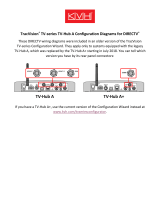
Follow the steps belows to connect power to the
system and set or verify the dish type or
configuration of each SWM receiver and/or DVR
connected to the TracVision system.
NOTE: Refer to your selected receiver/DVR manual
for specific configuration instructions.
a. Connect power to the TV-Hub and SWM
power inserters. For details, refer to the
TracVision UHD7 Installation Guide.
b. Press the Menu button on the receiver’s/
DVR’s remote control to display its menu on
the connected television.
c. Navigate to the Satellite screen (Settings >
Settings & Help > Satellite) and select Repeat
Satellite Setup.
d. At the Satellite Dish Setup menu, set the Dish
Type and RB/INTL to the settings below.
Switch Type should auto-populate:
Dish Type: SL3 LNB.
RD/INTL: None Selected
Switch Type: SWM Module 15 CH
e. Make any necessary changes, then choose
Continue to complete setup (see Figure 15).
f. Repeat these steps for each connected
receiver and DVR.
The procedure is complete!
Figure 15: DIRECTV SWM Receiver/DVR Configuration
Configure the Receivers
9
/