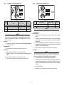
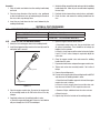
Victor 400 Series Heavy Duty Welding Handle Troubleshooting instruction
- Type
- Troubleshooting instruction

400 SERIES HEAVY DUTY
WELDING HANDLE
PARTS, SERVICE
& REPAIR BULLETIN
WH411C
VictorTechnologies.com
Issue Date: October 07, 2013
Manual No: 0056-3763 Revision: AA

2
Table of Contents
SECTION 1: GENERAL SAFETY INFORMATION ......................................2
1.01 Commonly Used Terms ...................................................2
SECTION 2: SPECIFICATIONS ................................................................3
2.01 WH411C Victor Welding Handle ...................................... 3
2.02 Repair Parts List ..............................................................3
SECTION 3: SERVICE & REPAIR INSTRUCTIONS ...................................4
3.01 Recommended Tools & Supplies for Repair Procedures . 4
3.02 Cleaning Procedures .......................................................4
3.03 Handle for 400 Series Welding Handle ............................4
3.04 Control Valve Repair Kit ...................................................5
3.05 Check Valve Repair Kit .....................................................5
3.06 Fuel and Oxygen Inlet Connections..................................6
3.07 Gas Feed Tubes ...............................................................6
SECTION 4: TEST PROCEDURES ...........................................................7
4.01 Recommended Tools & Supplies for Test Procedures .....7
4.02 Leak Testing the Welding Handle .....................................7
4.03 Testing the Check Valves .................................................8
SECTION 1: GENERAL SAFETY INFORMATION
Read and understand all safety and operating instructions provided before using this apparatus. RETAIN THESE INSTRUCTIONS IN A
READILY AVAILABLE LOCATION FOR FUTURE REFERENCE.
!
WARNING
DO NOT attempt to use this apparatus unless you are trained in its proper use or are under competent supervision. For your safety, practice
the safety and operating procedures described in this booklet every time you use the apparatus. Deviating from these procedures may result
in fire, explosion, property damage, and/or operator injury. If at any time the apparatus you are using does not perform in its usual manner, or
you have any difficulty in the use of the apparatus, STOP using it immediately. DO NOT use the apparatus until the problem has been corrected!
!
WARNING
Apparatus improperly operated, maintained or repaired can be dangerous. Some parts and accessories manufactured by others may fit
VICTOR apparatus but not conform to VICTOR’s exacting standards. For your own protection, specify and use ONLY VICTOR-made parts and
accessories with your VICTOR apparatus.
!
WARNING
Service or repair of apparatus should be performed only by a qualified repair technician capable of servicing gas apparatus in strict accordance
to applicable Part and Service bulletins for VICTOR manufactured products. Improper service repair, or modification of the product could result
in damage to the product or injury to the operator.
!
WARNING
WARNING: This product contains chemicals, including lead, known to the State of California to cause birth defects and other reproductive
harm. Wash hands after handling.
1.01 COMMONLY USED TERMS
BACKFIRE - The return of the flame into the torch, producing a popping sound. The flame will either extinguish or reignite at the tip.
SUSTAINED BACKFIRE - The return of the flame into the torch with continued burning within the torch. This condition may be accompanied
by a popping sound followed by a continuous hissing or whistling sound.
FLASHBACK - The return of the flame through the torch into the hose and even into the regulator. It may also reach the cylinder. This
condition could possibly cause an explosion in the system.

3
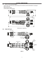
SECTION 2: SPECIFICATIONS
2.01 WH411C VICTOR WELDING HANDLE
• Intuitive knobs: color coded, clearly marked lettering with increase/decrease label; understandable in any language
• Built-in check valves
• High strength alloy handle
• Textured, precision contoured handle
3-1/8
1-1/2
2
8-1/8
1-5/8
2
All dimensions are approximate.
2.02 REPAIR PARTS LIST
Control Valve
Assembly
Inlet
Connection
Oxygen
Inlet
Connection
Fuel
Check
Valves
Left Handle
Gas Feed Tubes
Right Handle
Head
WH411C

4
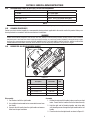
3.03 HANDLE FOR 400 SERIES WELDING HANDLE
4
3
1
2
Figure 3-1
Item
No.
Description Part number Qnty
Handle for 400 Series Welding Handle 0390-0093 1
1 Left Handle 0306-0293* 1
2 Right Handle 0306-0294* 1
3 Self-Threading Screw 1400-0250* 2
4 Decal for WH411C 1415-0852* 1
*Sold as part of kit only.
SECTION 3: SERVICE & REPAIR INSTRUCTIONS
3.01 RECOMMENDED TOOLS & SUPPLIES FOR REPAIR PROCEDURES
5/8”, 9/16”, and 11/16” Open-End Wrenches Vise
1/4-20 Bolt 45% Silver Solder
Pliers Silver Solder Flux
Hand Reamer RT-58 Loctite
®
#222 (Part Number 0028-0081)
Brazing Torch Christo-Lube
®
129 (Part Number 0034-0021)
NOTE
Disconnect the torch from any gas lines or other hardware before beginning any service or repair.
3.02 CLEANING PROCEDURES
Contact your local chemical supplier for recommended cleaning solvents applicable to the metals used in this product. Always use
cleaning solvents in accordance with the manufacturer’s instructions.
WARNING
DO NOT allow nonmetal components (seat, O-rings, dust seal, gaskets) to contact cleaning solvents! Cleaning solvents cause elastomeric
and plastic parts to swell and stress crack. If these parts require cleaning, use a mild soap solution, followed by a thorough rinsing in water.
Dry these parts completely before installing. REPLACE NONMETAL PARTS THAT HAVE COME IN CONTACT WITH OIL, GREASE OR ANY OTHER
PETROLEUM-BASED SUBSTANCE! Petroleum-based substances become dangerously flammable in the presence of oxygen.
Disassembly
1. Peel the decal off of the right handle.
2. Use a phillips head screwdriver to remove both screws from
the handle.
3. Separate the left handle from the right handle and remove
them from the gas feed tubes.
Assembly
1. Position the right and left handles in place over the gas feed
tubes. Ensure that the handles fit over the tubes correctly.
2. Hold the right and left handles together and fasten both
self-threading screws through the right handle into the left
handle.
3. Place the decal on the right handle as shown in Figure 3-1.

5
3.05 CHECK VALVE REPAIR KIT
+
+
1
Figure 3-3
Item
No.
Description Part number Qnty
Check Valve Repair Kit 0690-0027 1
1 Check Valve 0652-0029 2
NOTE
Follow these steps to disassemble and assemble either
check valve.
Disassembly
1. Screw the 1/4-20 bolt into the check valve until it is nger
tight.
2. Place the shank of the bolt in the vise. The head of the bolt
must catch on the vise jaws, and the bolt must be able to
move freely.
3. Grab the welding handle firmly and pull it up. The head of
the bolt will catch on the vise jaws, and the check valve will
pull out of the welding handle.
4. Repeat steps 1 through 3 for the other check valve.
Assembly
NOTE
This assembly requires a class “B” dual hose for oxygen and
fuel. The red hose connects to the fuel inlet connection. The
green hose connects to the oxygen inlet connection.
1. Press the check valve into the inlet connection.
2. Place the hose connection over the check valve and thread it
onto the inlet connection. Use a wrench to tighten the hose
onto the inlet connection until the check valve is properly
seated.
3. Remove the hose.
4. Repeat steps 1 through 3 for the other check valve.
3.04 CONTROL VALVE REPAIR KIT
1
3
+
+
2
Figure 3-2
Item
No.
Description Part number Qnty
Control Valve Repair Kit 0390-0086 2
1 Valve Stem Assembly 0662-0102* 1
2 Knob Decal (Red “F”) 1415-0864* 1
3 Knob Decal (Green “O”) 1415-0863* 1
*Sold as part of kit only.
NOTE
This welding handle uses two control valves. Follow these
steps to service, disassemble, and assemble either control
valve. The control valve repair kit includes only one valve
stem assembly.
Service
• Wipe with a dry cloth. Do not use any cleaning solvents.
• Check for leaks.
Disassembly
1. Use a wrench to unscrew the control valve nut.
Assembly
1. Apply Christo-Lube
®
to the assembly threads.
2. Screw the control valve assembly into the welding handle
body.
3. Use a wrench to tighten the control valve nut.
4. Place the correct decal on the knob (See Figure 3-2).

6
3.06 FUEL AND OXYGEN INLET CONNECTIONS
+
+
1
2
Figure 3-4
Item
No.
Description Part number Qnty
1 Oxygen Inlet Connection 0950-0099 1
2 Fuel Inlet Connection 0960-0073 1
NOTE
Follow these steps to disassemble and assemble either inlet
connection.
Disassembly
Remove the handle before beginning this task (see Section 3.03).
1. Place the welding handle in a vise.
2. Use a wrench to loosen and unscrew either inlet connection
from the welding handle.
3. Clean all debris from the inlet connection threads.
4. Repeat steps 2 and 3 for the other inlet connection.
Assembly
1. Apply a small amount of Loctite
®
to the beginning of the
inlet connection threads. Loctite
®
must completely cover
the beginning two threads of the inlet connection.
2. Screw the inlet connection onto the welding handle body
and wrench tighten.
3. Repeat steps 1 and 2 for the other inlet connection.
4. Remove the welding handle from the vise.
5. Install the check valves (see Section 3.05, Assembly).
6. Reattach the handle.
3.07 GAS FEED TUBES
CAUTION
Always wear gloves when handling heated parts.
2
1
Head Seat
Figure 3-5
Item
No.
Description Part number Qnty
Gas Feed Tubes 0390-0092 1
1 5/16” Tube 0303-0190* 1
2 3/8” Tube 0303-0200* 1
*Sold as part of kit only.
Service
1. Check the gas feed tubes for leaks and wear.
a. If you find a leak around the head, use hand reamer RT-58
to ream the head seat.
2. Remove all chips and debris from around the head seat area.
Disassembly
Remove the handle, control valves, and inlet connections before
beginning this task (see Sections 3.03, 3.04, and 3.06).
1. Place the large diameter of the head in a vise, positioned
so that the tube bores face up. Avoid placing the threads in
the vise as this may damage them.
2. Heat the gas feed tubes near the welding handle body until
the solder liquefies. Use pliers to remove the welding handle
body from the tubes.
3. Heat the gas feed tubes near the head until the solder
liquefies. Use pliers to remove the tubes from the head.
4. Allow all parts to cool before beginning assembly.

7
Assembly
1. Clean all solder and debris from the welding handle body
and head.
2. Place the large diameter of the head in a vise, positioned
so that the tube bores face up. Avoid placing the threads in
the vise as this may damage them.
3. Insert the gas feed tubes into the head, followed by the
welding handle body.
4. Solder the fitting around the head and repeat for the welding
handle body side. Allow all parts to cool before beginning
the next step.
5. Reattach the inlet connections, control valves, and handle.
6. Check for leaks and remove the welding handle from the
vise.
SECTION 4: TEST PROCEDURES
4.01 RECOMMENDED TOOLS & SUPPLIES FOR TEST PROCEDURES
Oil-free air or dry nitrogen supplies Plugged welding nozzle
RT-58 and RT-33 Reamers
5/8”, 9/16”, and 11/16” Open-end wrenches
Small water tank
Christo-Lube
®
129 (Part Number 0034-0021)
4.02 LEAK TESTING THE WELDING HANDLE
1. Attach the fuel and oxygen hoses to the welding handle.
2. Install the plugged welding nozzle in the head by hand. Do
not tighten with a wrench.
Plugged Hole
Welding Nozzle
Figure 4-1
3. Close the oxygen control valve. Pressurize the oxygen side
of the welding handle to 80 PSIG with oil-free air or dry
nitrogen.
4. Completely submerse the welding handle in water.
a. Check the oxygen inlet body port. If there is a leak, bubbles
will pass through the 1/4-NPT threaded port.
5. Open the oxygen and fuel control valves.
a. Check both control valve nuts, the gas feed tubes, and
all external connections. There should be no leakage (no
bubbles) for five seconds.
b. If there is a leak from one of the control valve nuts, tighten
it until 1-1/4 to 2 in-lbs of torque is required to adjust the
valve stem.
6. Close the oxygen control valve and remove the welding
handle from the water.
7. Depressurize both hoses and open the oxygen control valve.
8. Tighten each valve stem assembly knob to 7 to 8 in-lbs of
torque.
9. Remove the welding nozzle.
10. Pressurize the oxygen side of the welding handle to 80 PSIG
and submerse the welding handle in water.
a. Check the head. If bubbles appear at the head, the oxygen
control valve seat is leaking.
b. If there is a leak, you may have to reseat the valve seat.
Use valve seat reamer RT-33 to repair the valve seat.
c. Remove all chips and debris from the valve seat area.
d. Retest for leaks.
11. Repeat step 10 for the fuel side of the welding handle.

© 2012 Victor Technologies International, Inc. www.victortechnologies.com Printed in Mexico
U.S. Customer Care: 800-426-1888
•
Canada Customer Care: 905-827-4515
•
International Customer Care: 940-381-1212
INNOVATION TO SHAPE THE WORLD
™
T ECHNOLOGIES
™
THE AMERICAS
Denton, TX USA
U.S. Customer Care
Ph: 1-800-426-1888 (tollfree)
Fax: 1-800-535-0557 (tollfree)
International Customer Care
Ph: 1-940-381-1212
Fax: 1-940-483-8178
Miami, FL USA
Sales Office, Latin America
Ph: 1-954-727-8371
Fax: 1-954-727-8376
Oakville, Ontario, Canada
Canada Customer Care
Ph: 1-905-827-4515
Fax: 1-800-588-1714 (tollfree)
EUROPE
Chorley, United Kingdom
Customer Care
Ph: +44 1257-261755
Fax: +44 1257-224800
Milan, Italy
Customer Care
Ph: +39 0236546801
Fax: +39 0236546840
ASIA/PACIFIC
Cikarang, Indonesia
Customer Care
Ph: 6221-8990-6095
Fax: 6221-8990-6096
Rawang, Malaysia
Customer Care
Ph: +603 6092-2988
Fax: +603 6092-1085
Melbourne, Australia
Australia Customer Care
Ph: 1300-654-674 (tollfree)
Ph: 61-3-9474-7400
Fax: 61-3-9474-7391
International
Ph: 61-3-9474-7508
Fax: 61-3-9474-7488
Shanghai, China
Sales Office
Ph: +86 21-64072626
Fax: +86 21-64483032
Singapore
Sales Office
Ph: +65 6832-8066
Fax: +65 6763-5812
4.03 TESTING THE CHECK VALVES
WARNING
The 400 Series Welding Handle is equipped with internal check
valves to prevent gases from mixing in the hoses or regulators. Mixed
gases may result in a fire or explosion that can cause serious injury.
Test the check valves at least every six months. Test them more often
if the hoses are frequently disconnected from the welding handle.
1. Remove the small O-ring from the plugged welding nozzle
and install the nozzle in the head of the welding handle.
Removing the O-ring ensures that, for testing purposes only,
back pressure will reach the check valves.
2. Connect the fuel and oxygen hoses to the welding handle.
3. Disconnect either the fuel hose from the fuel regulator or
the oxygen hose from the oxygen regulator.
4. Open both the fuel and oxygen valve stem assemblies.
5. Open the cylinder or manifold valve. Adjust the regulator
that is still connected to deliver 2-5 PSIG.
6. Place the loose end of the disconnected hose under water
for at least ten seconds.
7. Check the hose end for bubbles. If there is more than one
bubble in five seconds, replace the check valve.
8. Repeat steps 3 through 7 to test the other check valve.
Plugged Hole
Welding Nozzle
Small O-Ring
Figure 4-2
-
 1
1
-
 2
2
-
 3
3
-
 4
4
-
 5
5
-
 6
6
-
 7
7
-
 8
8


Victor 400 Series Heavy Duty Welding Handle Troubleshooting instruction
- Type
- Troubleshooting instruction
Ask a question and I''ll find the answer in the document
Finding information in a document is now easier with AI
Related papers
-
ESAB 400 Series Heavy Duty Cutting Attachment Troubleshooting instruction
-
-
-
-
-
-
-
-
-
Other documents
-
Milwaukee 58-01-0646 Wiring Instructions
-
-
Linde AGA Series Operating instructions
-
-
-
ESAB Air/Fuel Hand Torch User manual
-
 SSP LP Rising Rising Plug Valve Maintenance Instructions
-
-
-
